AES 1156

AES 1156
Downloads
- Monitoring of BNS range magnetic safety sensors
- 1 safety contact, STOP 0
Ordering data
| Note (Delivery capacity) |
Leveres ikke længere! |
| Product type description |
AES 1156 |
| Article number (order number) |
101170042 |
| EAN (European Article Number) |
4030661296975 |
| eCl@ss number, version 12.0 |
27-37-18-19 |
| eCl@ss number, version 11.0 |
27-37-18-19 |
| eCl@ss number, version 9.0 |
27-37-18-19 |
| ETIM number, version 7.0 |
EC001449 |
| ETIM number, version 6.0 |
EC001449 |
Approvals - Standards
| Certificates |
cULus |
General data
| Standards |
BG-GS-ET-14 BG-GS-ET-20 EN IEC 62061 EN ISO 13849-1 EN IEC 60947-5-1 EN IEC 60947-5-3 EN IEC 60947-5-5 EN IEC 60204-1 EN IEC 60947-1 |
| Climatic stress |
EN 60068-2-3 BG-GS-ET-14 |
| Housing material |
Plastik, glass-fibre reinforced thermoplastic, ventileret |
| Gross weight |
198 g |
General data - Features
| Wire breakage detection |
Ja |
| Cross-circuit detection |
Ja |
| Automatic reset function |
Ja |
| Start-up test |
Ja |
| Earth connection detection |
Ja |
| Integral system diagnostics, status |
Ja |
| Number of LEDs |
1 |
| Number of normally closed (NC) |
2 |
| Number of normally open (NO) |
2 |
| Number of undelayed semi-conductor outputs with signaling function |
2 |
| Number of safety contacts |
1 |
| Safety classification |
| Vorschriften |
EN ISO 13849-1 EN IEC 61508 |
| Stop-Category |
0 |
| Safety classification - Relay outputs |
| Performance Level, up to |
d |
| Category |
3 |
| PFH value |
1,00 x 10⁻⁷ /h |
| Notice |
op til maks. 50.000 skiftecykluser/år og nær maks. 80 % kontaktbelastning |
| Safety Integrity Level (SIL), suitable for applications in |
2 |
| Mission time |
20 Year(s) |
Mechanical data
| Mechanical life, minimum |
20.000.000 Operations |
| Mounting |
Hurtig montage på standard DIN-skinne iht. DIN EN 60715 |
Mechanical data - Connection technique
| Terminal designations |
IEC/EN 60947-1 |
| Termination |
stiv eller fleksibel Skrueforbindelse M20 x 1.5 |
| Cable section, minimum |
0,25 mm² |
| Cable section, maximum |
2,5 mm² |
| Tightening torque of Clips |
0,6 Nm |
Mechanical data - Dimensions
| Width |
22,5 mm |
| Height |
100 mm |
| Depth |
121 mm |
Ambient conditions
| Degree of protection of the enclosure |
IP40 |
| Degree of protection of the mounting space |
IP54 |
| Degree of protection of clips or terminals |
IP20 |
| Ambient temperature |
+0 ... +55 °C |
| Storage and transport temperature |
-25 ... +70 °C |
| Resistance to vibrations |
10 … 55 Hz, amplitude 0,35 mm, ± 15 % |
| Restistance to shock |
30 g / 11 ms |
Ambient conditions - Insulation values
| Rated impulse withstand voltage Uimp |
4 kV |
| Overvoltage category |
III |
| Degree of pollution |
2 |
Electrical data
| Frequency range |
50 Hz 60 Hz |
| Operating voltage |
24 VAC -15 % / +10 % |
| Ripple voltage |
10 % |
| Thermal test current |
6 A |
| Rated operating voltage |
24 VAC |
| Rated operating voltage |
24 VDC |
| Rated AC voltage for controls, 50 Hz, minimum |
20,4 VAC |
| Rated control voltage at AC 50 Hz, maximum |
26,4 VAC |
| Rated AC voltage for controls, 60 Hz, minimum |
20,4 VAC |
| Rated control voltage at AC 60 Hz, maximum |
26,4 VAC |
| Rated AC voltage for controls at DC minimum |
20,4 VDC |
| Rated control voltage at DC, maximum |
28,8 VDC |
| Electrical power consumption |
5 W |
| Contact resistance, maximum |
0,1 Ω |
| Note (Contact resistance) |
i ny tilstand |
| Drop-out delay in case of power failure, typically |
80 ms |
| Drop-out delay in case of emergency, typically |
20 ms |
| Pull-in delay at automatic start, maximum, typically |
100 ms |
| Pull-in delay at RESET, typically |
20 ms |
| Material of the contacts, electrical |
Ag-Ni 10 og 0,2 µm guld flashet |
Electrical data - Safe relay outputs
| Voltage, Utilisation category AC-15 |
230 VAC |
| Current, Utilisation category AC-15 |
6 A |
| Voltage, Utilisation category DC-13 |
24 VDC |
| Current, Utilisation category DC-13 |
6 A |
| Switching capacity, minimum |
10 VDC |
| Switching capacity, minimum |
10 mA |
| Switching capacity, maximum |
250 VAC |
| Switching capacity, maximum |
8 A |
Electrical data - Digital inputs
| Input signal, HIGH Signal "1" |
10 … 30 VDC |
| Input signal, LOW Signal "0" |
0 … 2 VDC |
| Conduction resistance, maximum |
40 Ω |
Electrical data - Digital Output
| Voltage, Utilisation category DC-12 |
24 VDC |
| Current, Utilisation category DC-12 |
0,1 A |
Electrical data - Relay outputs (auxiliary contacts)
| Switching capacity, maximum |
24 VDC |
| Switching capacity, maximum |
2 A |
Electrical data - Electromagnetic compatibility (EMC)
| EMC rating |
EMC-direktivet |
Integral system diagnosis (ISD)
| Note (ISD -Faults) |
De følgende fejl registreres af sikkerhedsovervågningsmodulerne og indikeres af ISD. |
| Faults |
Fejl i sikkerhedsrelæet til pull-in eller drop-ud Dørkontakter kunne enten ikke åbne eller lukke Overvågning af kortslutninger eller krydsede ledninger i afbryderforbindelserne Afbrydelse af afbryderforbindelserne Fejl i sikkerhedsmonitormodulets indgangskredsløb eller relækontrolkredsløb |
Other data
| Note (applications) |
Sikkerhedsføler Beskyttelsessystem |
Note
| Note (General) |
Induktive belastninger (f.eks. kontaktorer, relæer) skal undertrykkes med hjælp af et passende kredsløb. |
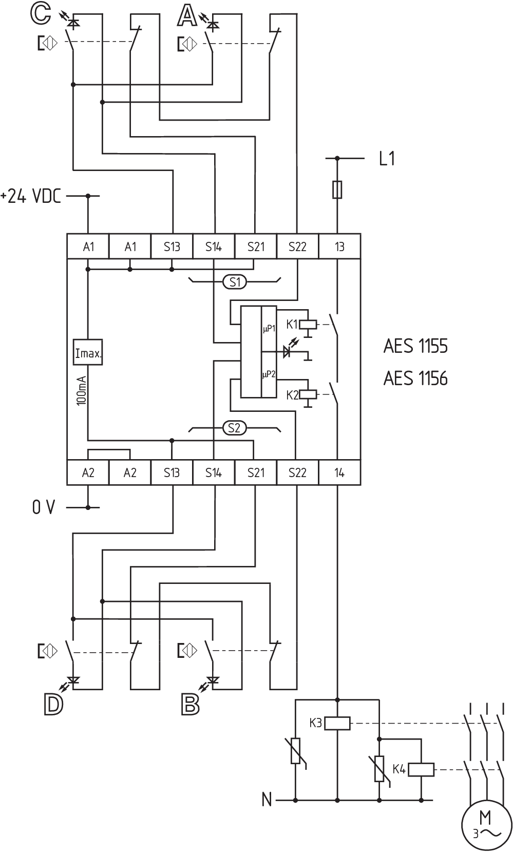
Wiring example
| Note (Wiring diagram) |
Overvågning af et antal beskyttelsesdøre med magnetiske sikkerhedsfølere fra BNS-rækken Ledningsdiagrammet vises med sikkerhedsafskærmninger lukkede og i deaktiveret tilstand. Hvis én eller to eksterne relæer eller kontaktorer anvendes til at afbryde belastningen, kan systemet kun klassificeres i kategori 3 til EN ISO 13849-1, hvis udelukkelse af fejlen “Fejl i de eksterne kontaktorer” kan understøttes og dokumenteres, f.eks. ved at anvende pålidelige nedklassificerede kontaktorer. En anden kontaktor leder til en stigning af sikkerhedsniveauet ved overskydende afbrydelse af belastningen. ISD-tabellerne (Intergreret systemdiagnose), til analyse af fejlindikationerne og deres årsag, vises i tillægget. Til sikring af en eller flere beskyttelsesenheder op til PL d og kategori 3 NC-kontakten skal have tvangsåbning når beskyttelsesdøren åbnes. Udvidelse af aktiveringsforsinkelsestiden: Aktiveringsforsinkelsestiden kan øges fra 0,1 s til 1 s ved at ændre placeringen af en jumper link-forbindelse under enhedens dæksel. |
Sprog filter
Datablad
Driftsvejledning og Erklæring om konformitet
UL-certifikat
Ledningseksempel (el-ledningsføring)
Hent sidste version af Adobe Reader
Produktbillede (katalogenkeltfoto)
Ledningseksempel
103008070 SRB-E-204PE
- Plug-in screw terminals with coding
- Input expander module
- 1 oder 2-channel control
- Monitoring of 4 sensors
- 2 Safety outputs
- 4 Signalling outputs

103009973 SRB-E-204ST
- Plug-in screw terminals with coding
- STOP 0 Function
- Monitoring of 4 sensors
- Start button / Auto-start
- 2 Safety outputs
- 4 Signalling outputs
| EU Declaration of Conformity |  |
| Original | K.A. Schmersal GmbH & Co. KG Möddinghofe 30 42279 Wuppertal Germany Internet: www.schmersal.com |
| Declaration: | We hereby certify that the hereafter described components both in their basic design and construction conform to the applicable European Directives. |
| Name of the component: | AES 1135/1136 AES 1165/1165-2250 AES 1235/1236 AES 1265/1265-2250 AES 2135 AES 2335/2365 AES 2535 |
| Type: | See ordering code |
| Description of the component: | Safety-monitoring module |
| Relevant Directives: | Machinery Directive | 2006/42/EC |
| EMC-Directive | 2014/30/EU | |
| RoHS-Directive | 2011/65/EU |
| Applied standards: | DIN EN 60947-5-1:2018 DIN EN ISO 13849-1:2016 DIN EN ISO 13849-2:2013 |
| Notified body, which approved the full quality assurance system, referred to in Appendix X, 2006/42/EC: | TÜV Rheinland Industrie Service GmbH Am Grauen Stein, 51105 Köln ID n°: 0035 |
| Person authorised for the compilation of the technical documentation: | Oliver Wacker Möddinghofe 30 42279 Wuppertal |
| Place and date of issue: | Wuppertal, January 31, 2024 |
 |
| Authorised signature Philip Schmersal Managing Director |
Schmersal India Pvt. Ltd., Plot No - G-7/1, Ranjangaon MIDC, Tal. - Shirur, Dist.- Pune 412 220
De nævnte data og angivelser er blevet checket omhyggeligt. Billeder kan afvige fra originalen. Der kan findes flere tekniske data i manualen. Der tages forbehold for tekniske ændringer og fejl.
Udarbejdet d. 06.05.2025 04.29