AES 1265

AES 1265
- Monitoring of BNS range magnetic safety sensors
- 2 safety contacts, STOP 0
Ordering data
| Note (Delivery capacity) |
Udgående produkt |
| Product type description |
AES 1265 |
| Article number (order number) |
101170051 |
| EAN (European Article Number) |
4030661297132 |
| eCl@ss number, version 12.0 |
27-37-18-19 |
| eCl@ss number, version 11.0 |
27-37-18-19 |
| eCl@ss number, version 9.0 |
27-37-18-19 |
| ETIM number, version 7.0 |
EC001449 |
| ETIM number, version 6.0 |
EC001449 |
| Notice |
Udgående produkt |
Approvals - Standards
| Certificates |
cULus |
General data
| Standards |
BG-GS-ET-14 BG-GS-ET-20 EN IEC 62061 EN ISO 13849-1 EN IEC 60947-5-1 EN IEC 60947-5-3 EN IEC 60947-5-5 EN IEC 60204-1 EN IEC 60947-1 |
| Climatic stress |
EN 60068-2-3 BG-GS-ET-14 |
| Housing material |
Plastik, glass-fibre reinforced thermoplastic, ventileret |
| Gross weight |
174 g |
General data - Features
| Wire breakage detection |
Ja |
| Cross-circuit detection |
Ja |
| Feedback circuit |
Ja |
| Automatic reset function |
Ja |
| Reset after disconnection of supply voltage |
Ja |
| Earth connection detection |
Ja |
| Integral system diagnostics, status |
Ja |
| Number of LEDs |
1 |
| Number of normally closed (NC) |
2 |
| Number of normally open (NO) |
2 |
| Number of undelayed semi-conductor outputs with signaling function |
2 |
| Number of safety contacts |
2 |
| Number of signalling outputs |
2 |
| Safety classification |
| Vorschriften |
EN ISO 13849-1 EN IEC 61508 |
| Stop-Category |
0 |
| Safety classification - Relay outputs |
| Performance Level, up to |
d |
| Category |
3 |
| PFH value |
1,00 x 10⁻⁷ /h |
| Notice |
op til maks. 50.000 skiftecykluser/år og nær maks. 80 % kontaktbelastning |
| Safety Integrity Level (SIL), suitable for applications in |
2 |
| Mission time |
20 Year(s) |
Mechanical data
| Mechanical life, minimum |
20.000.000 Operations |
| Mounting |
Hurtig montage på standard DIN-skinne iht. DIN EN 60715 |
Mechanical data - Connection technique
| Terminal designations |
IEC/EN 60947-1 |
| Termination |
stiv eller fleksibel Skrueforbindelse M20 x 1.5 |
| Cable section, minimum |
0,25 mm² |
| Cable section, maximum |
2,5 mm² |
| Tightening torque of Clips |
0,6 Nm |
Mechanical data - Dimensions
| Width |
22,5 mm |
| Height |
100 mm |
| Depth |
121 mm |
Ambient conditions
| Degree of protection of the enclosure |
IP40 |
| Degree of protection of the mounting space |
IP54 |
| Degree of protection of clips or terminals |
IP20 |
| Ambient temperature |
+0 ... +55 °C |
| Storage and transport temperature |
-25 ... +70 °C |
| Resistance to vibrations |
10 … 55 Hz, amplitude 0,35 mm, ± 15 % |
| Restistance to shock |
30 g / 11 ms |
Ambient conditions - Insulation values
| Rated impulse withstand voltage Uimp |
4 kV |
| Overvoltage category |
III |
| Degree of pollution |
2 |
Electrical data
| Frequency range |
50 Hz 60 Hz |
| Operating voltage |
24 VAC -15 % / +10 % |
| Ripple voltage |
10 % |
| Thermal test current |
6 A |
| Rated operating voltage |
24 VAC |
| Rated operating voltage |
24 VDC |
| Rated AC voltage for controls, 50 Hz, minimum |
20,4 VAC |
| Rated control voltage at AC 50 Hz, maximum |
26,4 VAC |
| Rated AC voltage for controls, 60 Hz, minimum |
20,4 VAC |
| Rated control voltage at AC 60 Hz, maximum |
26,4 VAC |
| Rated AC voltage for controls at DC minimum |
20,4 VDC |
| Rated control voltage at DC, maximum |
28,8 VDC |
| Electrical power consumption |
5 W |
| Contact resistance, maximum |
0,1 Ω |
| Note (Contact resistance) |
i ny tilstand |
| Drop-out delay in case of power failure, typically |
80 ms |
| Drop-out delay in case of emergency, typically |
20 ms |
| Pull-in delay at automatic start, maximum, typically |
100 ms |
| Pull-in delay at RESET, typically |
20 ms |
| Material of the contacts, electrical |
Ag-Ni 10 og 0,2 µm guld flashet |
Electrical data - Safe relay outputs
| Voltage, Utilisation category AC-15 |
230 VAC |
| Current, Utilisation category AC-15 |
6 A |
| Voltage, Utilisation category DC-13 |
24 VDC |
| Current, Utilisation category DC-13 |
6 A |
| Switching capacity, minimum |
10 VDC |
| Switching capacity, minimum |
10 mA |
| Switching capacity, maximum |
250 VAC |
| Switching capacity, maximum |
8 A |
Electrical data - Digital inputs
| Input signal, HIGH Signal "1" |
10 … 30 VDC |
| Input signal, LOW Signal "0" |
0 … 2 VDC |
| Conduction resistance, maximum |
40 Ω |
Electrical data - Digital Output
| Voltage, Utilisation category DC-12 |
24 VDC |
| Current, Utilisation category DC-12 |
0,1 A |
Electrical data - Relay outputs (auxiliary contacts)
| Switching capacity, maximum |
24 VDC |
| Switching capacity, maximum |
2 A |
Electrical data - Electromagnetic compatibility (EMC)
| EMC rating |
EMC-direktivet |
Integral system diagnosis (ISD)
| Note (ISD -Faults) |
De følgende fejl registreres af sikkerhedsovervågningsmodulerne og indikeres af ISD. |
| Faults |
Fejl i sikkerhedsrelæet til pull-in eller drop-ud Dørkontakter kunne enten ikke åbne eller lukke Overvågning af kortslutninger eller krydsede ledninger i afbryderforbindelserne Afbrydelse af afbryderforbindelserne Fejl i sikkerhedsmonitormodulets indgangskredsløb eller relækontrolkredsløb |
Other data
| Note (applications) |
Sikkerhedsføler Beskyttelsessystem |
Note
| Note (General) |
Induktive belastninger (f.eks. kontaktorer, relæer) skal undertrykkes med hjælp af et passende kredsløb. |
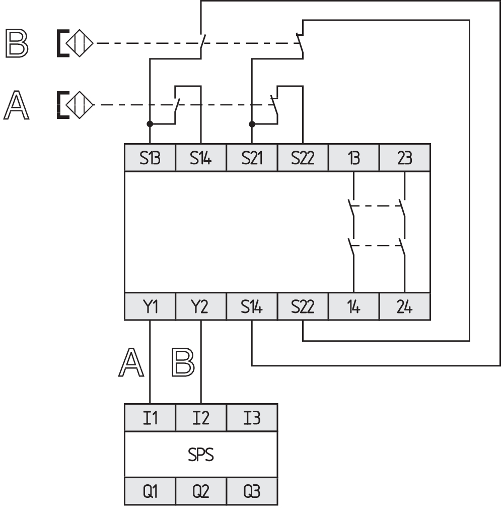
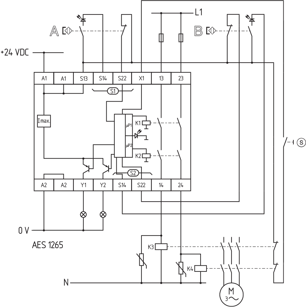
Wiring example
| Note (Wiring diagram) |
Ledningsdiagrammet vises med sikkerhedsafskærmninger lukkede og i deaktiveret tilstand. Overvågning af 2 beskyttelsesdør(e), hver med en magnetisk sikkerhedsføler fra BNS-rækken ISD-tabellerne (Intergreret systemdiagnose), til analyse af fejlindikationerne og deres årsag, vises i tillægget. Udvidelse af aktiveringsforsinkelsestiden: Aktiveringsforsinkelsestiden kan øges fra 0,1 s til 1 s ved at ændre placeringen af en jumper link-forbindelse under enhedens dæksel. Til sikring af 2 beskyttelsesenheder op til PL d og kategori 3 Feedback-kredsløbene overvåger placeringen af kontaktorerne K3 og K4 Starttaste (S): Der kan evt. tilsluttes en starttaste (slutter) i tilbagekoblingssløjfen. Er beskyttelsesanordningen lukket, lukkes sikkerhedskontakterne først, når der trykkes på starttasten. Hvis kun et eksternt relæ eller kontaktor anvendes til at afbryde belastningen, kan systemet klassificeres i kategori 3 til ISO 13849-1, hvis udelukkelse af fejlen “Fejl i de eksterne kontaktorer” kan understøttes og dokumenteres, f.eks. ved at anvende pålidelige nedklassificerede kontaktorer. En anden kontaktor leder til en stigning af sikkerhedsniveauet ved overskydende afbrydelse af belastningen. Hvis hverken startknappen eller feedback-kredsløbet er forbundet, skal der monteres en jumper-forbindelse mellem X1 og A1. |
Sprog filter
Datablad
Driftsvejledning og Erklæring om konformitet
UL-certifikat
Ledningseksempel (el-ledningsføring)
SISTEMA-VDMA bibliotek/library
Hent sidste version af Adobe Reader
Produktbillede (katalogenkeltfoto)
Ledningseksempel
Ledningseksempel

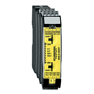
103009973 SRB-E-204ST
- Plug-in screw terminals with coding
- STOP 0 Function
- Monitoring of 4 sensors
- Start button / Auto-start
- 2 Safety outputs
- 4 Signalling outputs
103041495 SRB-E-302ST
- Monitoring of 2 sensors STOP 0
- 1 oder 2-channel control
- Start button / Auto-start
- 2 Safety contacts, 1 Safety Output
- 2 Signalling outputs
| EU Declaration of Conformity |  |
| Original | K.A. Schmersal GmbH & Co. KG Möddinghofe 30 42279 Wuppertal Germany Internet: www.schmersal.com |
| Declaration: | We hereby certify that the hereafter described components both in their basic design and construction conform to the applicable European Directives. |
| Name of the component: | AES 1135/1136 AES 1165/1165-2250 AES 1235/1236 AES 1265/1265-2250 AES 2135 AES 2335/2365 AES 2535 |
| Type: | See ordering code |
| Description of the component: | Safety-monitoring module |
| Relevant Directives: | Machinery Directive | 2006/42/EC |
| EMC-Directive | 2014/30/EU | |
| RoHS-Directive | 2011/65/EU |
| Applied standards: | DIN EN 60947-5-1:2018 DIN EN ISO 13849-1:2016 DIN EN ISO 13849-2:2013 |
| Notified body, which approved the full quality assurance system, referred to in Appendix X, 2006/42/EC: | TÜV Rheinland Industrie Service GmbH Am Grauen Stein, 51105 Köln ID n°: 0035 |
| Person authorised for the compilation of the technical documentation: | Oliver Wacker Möddinghofe 30 42279 Wuppertal |
| Place and date of issue: | Wuppertal, January 31, 2024 |
 |
| Authorised signature Philip Schmersal Managing Director |
Schmersal India Pvt. Ltd., Plot No - G-7/1, Ranjangaon MIDC, Tal. - Shirur, Dist.- Pune 412 220
De nævnte data og angivelser er blevet checket omhyggeligt. Billeder kan afvige fra originalen. Der kan findes flere tekniske data i manualen. Der tages forbehold for tekniske ændringer og fejl.
Udarbejdet d. 06.05.2025 20.29
Set fornylig