SRB202MSK
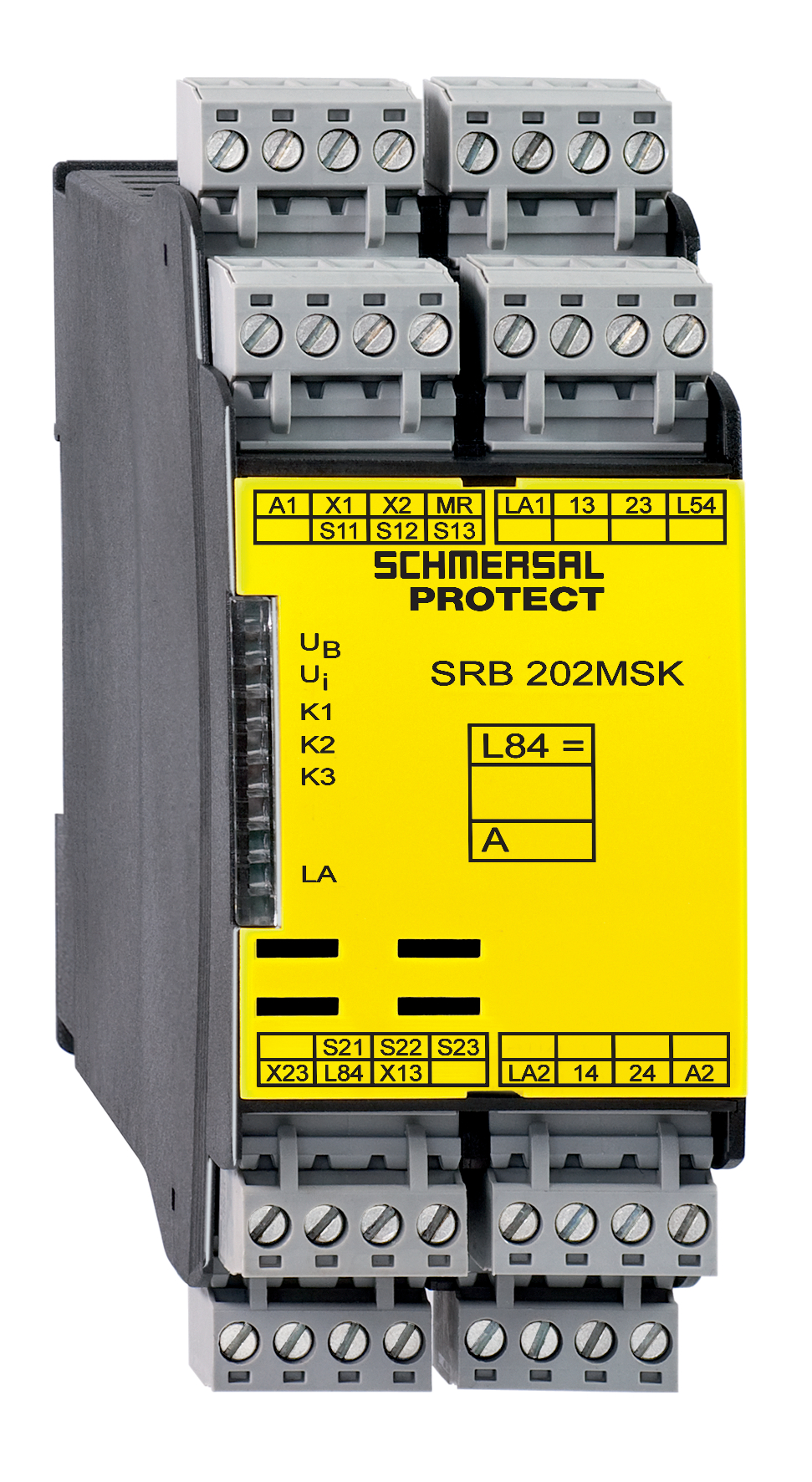
SRB202MSK
Downloads
- Muting signalling device monitoring
- 2 safety contacts, STOP 0
- 2 Signalling outputs
Ordering data
| Note (Delivery capacity) |
Leveres ikke længere! |
| Product type description |
SRB202MSK |
| Article number (order number) |
101191928 |
| eCl@ss number, version 12.0 |
27-37-18-19 |
| eCl@ss number, version 11.0 |
27-37-18-19 |
| eCl@ss number, version 9.0 |
27-37-18-19 |
| ETIM number, version 7.0 |
EC001449 |
| ETIM number, version 6.0 |
EC001449 |
General data
| Standards |
EN IEC 62061 EN ISO 13849-1 EN IEC 60947-5-1 EN IEC 60947-5-3 EN IEC 60947-5-5 EN IEC 61508 EN IEC 60204-1 EN IEC 60947-1 |
| Climatic stress |
EN 60068-2-78 |
| Housing material |
Plastik, glass-fibre reinforced thermoplastic, ventileret |
| Gross weight |
330 g |
General data - Features
| Electronic Fuse |
Ja |
| Wire breakage detection |
Ja |
| Removable Terminals |
Ja |
| Feedback circuit |
Ja |
| Automatic reset function |
Ja |
| Earth connection detection |
Ja |
| Integral system diagnostics, status |
Ja |
| Number of auxiliary contacts |
2 |
| Number of inputs for NC |
2 |
| Number of LEDs |
8 |
| Number of safety contacts |
2 |
| Number of signalling outputs |
2 |
| Safety classification |
| Vorschriften |
EN IEC 60947-5-1 EN IEC 61508 |
| Stop-Category |
0 |
| Safety classification - Relay outputs |
| Performance Level, stop 0, up to |
e |
| Category, Stop 0 |
4 |
| Diagnostic Coverage (DC) Level, Stop 0 |
≥ 99 % |
| PFH value, Stop 0 |
2,00 x 10⁻⁸ /h |
| Safety Integrity Level (SIL), Stop 0, suitable for applications in |
3 |
| Mission time |
20 Year(s) |
| Common Cause Failure (CCF), minimum |
65 |
Mechanical data
| Mechanical life, minimum |
10.000.000 Operations |
| Mounting |
Hurtig montage på standard DIN-skinne iht. DIN EN 60715 |
Mechanical data - Connection technique
| Terminal designations |
IEC/EN 60947-1 |
| Termination |
stiv eller fleksibel Skrueforbindelse M20 x 1.5 |
| Cable section, minimum |
0,25 mm² |
| Cable section, maximum |
2,5 mm² |
| Tightening torque of Clips |
0,6 Nm |
Mechanical data - Dimensions
| Width |
45 mm |
| Height |
100 mm |
| Depth |
121 mm |
Ambient conditions
| Degree of protection of the enclosure |
IP40 |
| Degree of protection of the mounting space |
IP54 |
| Degree of protection of clips or terminals |
IP20 |
| Ambient temperature |
-25 ... +45 °C |
| Storage and transport temperature |
-40 ... +85 °C |
| Resistance to vibrations |
10 … 55 Hz, amplitude 0,35 mm, ± 15 % |
| Restistance to shock |
30 g / 11 ms |
Ambient conditions - Insulation values
| Rated impulse withstand voltage Uimp |
4 kV |
| Overvoltage category |
III |
| Degree of pollution |
2 |
Electrical data
| Operating voltage |
24 VDC -10 % / +20 % |
| Ripple voltage |
10 % |
| Rated operating voltage |
24 VDC |
| Rated AC voltage for controls at DC minimum |
20,4 VDC |
| Rated control voltage at DC, maximum |
28,8 VDC |
| Utilisation category DC-13 |
24 VDC |
| Utilisation category DC-13 |
2 A |
| Electrical power consumption |
3,1 W |
| Contact resistance, maximum |
0,1 Ω |
| Note (Contact resistance) |
i ny tilstand |
| Drop-out delay in case of power failure, typically |
60 ms |
| Drop-out delay in case of "emergency stop", maximum |
20 ms |
| Pull-in delay at automatic start, maximum, typically |
200 ms |
| Material of the contacts, electrical |
AgSn0, Ag-Ni, selvrensende, tvangsstyret |
Electrical data - Digital inputs
| Conduction resistance, maximum |
40 Ω |
Electrical data - Electromagnetic compatibility (EMC)
| EMC rating |
EMC-direktivet |
Status indication
| Indicated operating states |
Position relæ K2 Position relæ K1 Intern driftsspænding Ui Position relæ K3 Position relæ K5 Placering af den dæmpende signalenhed LA |
Other data
| Note (applications) |
Mutingfunktion |
Note
| Note (General) |
Induktive belastninger (f.eks. kontaktorer, relæer) skal undertrykkes med hjælp af et passende kredsløb. |
Wiring example
| Note (Wiring diagram) |
Relæudgange: Passende til 2 kanalkontrol, for øget kapacitet eller antal kontakter ved hjælp af kontaktorer eller relæer med positivt-guidede kontakter. Kontrollen genkender kortslutning, kabelbrud og jordlækager i overvågningskredsløbet. Eksemplet viser en 2-kanals kontrol af 2 dæmpningsfølere og en ekstern master reset-knap. Ledningsdiagrammet vises med ikke-aktiverede grænseafbrydere og i deaktiveret tilstand. (H2) = Feedback-strømkreds F1 = Elektronisk sikring |
Sprog filter
Datablad
Driftsvejledning og Erklæring om konformitet
Hent sidste version af Adobe Reader
Produktbillede (katalogenkeltfoto)
Symbol (teknisk standard)

Schmersal India Pvt. Ltd., Plot No - G-7/1, Ranjangaon MIDC, Tal. - Shirur, Dist.- Pune 412 220
De nævnte data og angivelser er blevet checket omhyggeligt. Billeder kan afvige fra originalen. Der kan findes flere tekniske data i manualen. Der tages forbehold for tekniske ændringer og fejl.
Udarbejdet d. 27.04.2025 23.14
Set fornylig
BN 65-RZ/V