BN 85-R-1831-2 1,0M
BN 85-R-1831-2 1,0M
Downloads
- Mounting with clamping brackets and 2 single wires
- Mounting on C DIN rail and 2 single wires with screws
- Non-contact principle
- 1 Reed contakts
- Long life
- Actuating distance up to 40 mm depending on actuating magnet and version
- 40 mm x 35 mm x 16,5 mm
- Thermoplastic enclosure
- Reed-contact to clip-in, on-location assembly
Ordering data
| Product type description |
BN 85-R-1831-2 1,0M |
| Article number (order number) |
101099930 |
| EAN (European Article Number) |
4030661023526 |
| eCl@ss number, version 12.0 |
27-27-43-02 |
| eCl@ss number, version 11.0 |
27-27-01-05 |
| eCl@ss number, version 9.0 |
27-27-01-05 |
| ETIM number, version 7.0 |
EC002544 |
| ETIM number, version 6.0 |
EC002544 |
General data
| Working principle |
magnetisch |
| Versions |
Reedkontakteinsatz und Sockel |
| Housing construction form |
Quader |
| Housing material |
Kunststoff, glasfaserverstärkter Thermoplast |
| Gross weight |
40 g |
General data - Features
| Latching |
Ja |
| Suitable for elevators |
Ja |
| Number of snap-in contacts |
1 |
Mechanical data
| Active area |
vorderseitig |
| Mechanical lifetime, minimum |
1.000.000.000 Operations |
| Actuation direction |
Längsrichtung |
| Actuating speed, maximum |
18 m/s |
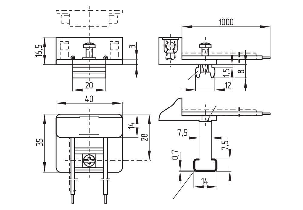
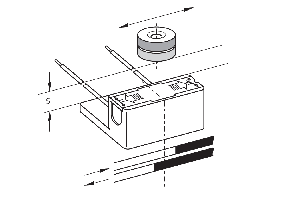
| Mounting |
Klemmleiste 7,5 mm |
Mechanical data - Switching distances
| Switching distance Sn |
2 mm … 40 mm BP 6S = 2 … 12 mm BP 8S = 2 … 10 mm BP 10S = 5 … 20 mm 2 x BP 10S = 6 … 27 mm BP 15S = 5 … 22 mm 2 x BP 15S = 7 … 28 mm BP 34S = 10 … 40 mm BP 20S = 3 ... 28 mm BP 31S = 4 ... 30 mm BP 11S = 4 ... 23 mm BP 12S = 5 ... 27 mm |
| Note (Switching distance Sn) |
Schaltabstand bis zu 40 mm, abhängig vom Betätigungsmagnet und Ausführung. Die Angaben zu den Schaltabständen gelten bei Betätigung einzeln montierter Geräte ohne ferromagnetischen Einfluss. Eine Veränderung des Abstandes, positiv wie negativ, ist durch ferromagnetischen Einfluss möglich. Bei der Anordnung von mehreren Betätigungsmagneten ist die gegenseitige Beeinflussung zu berücksichtigen. |
| Note (switching distance) |
Alle Angaben der Schaltabstände gemäß EN IEC 60947-5-2 |
Mechanical data - Connection technique
| Length of cable |
1 m |
| Termination |
einzelne Litzen |
| Number of cable wires |
2 |
| Wire cross-section |
0,75 mm2 |
| Wire cross-section |
18 AWG |
| Material of the Cable mantle |
PVC |
Mechanical data - Dimensions
| Length of sensor |
16,5 mm |
| Width of sensor |
40 mm |
| Height of sensor |
35 mm |
Ambient conditions
| Degree of protection |
IP40 |
| Ambient temperature |
+0 ... +75 °C |
| Restistance to shock |
60 g, sinusförmige Schwingung |
| Resistant to vibration |
60 g, sinusförmige Schwingung |
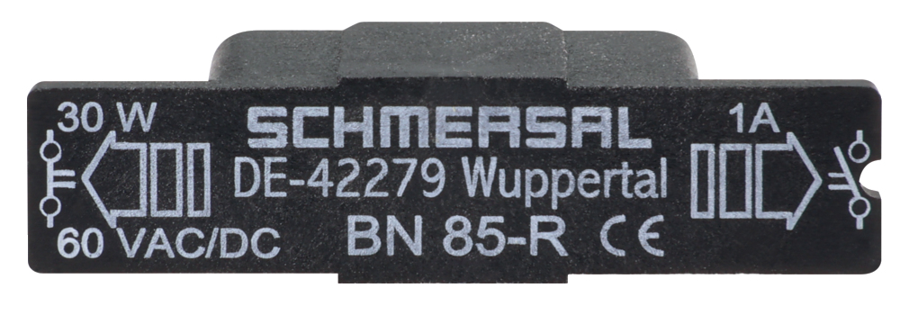
Electrical data
| Switching voltage, maximum |
60 VAC |
| Switching voltage, maximum |
60 VDC |
| Switching current, maximum |
1 A |
| Switching capacity, maximum |
30 W |
| Switching capacity, maximum |
30 VA |
| Note (Switching element) |
Reedkontakteinsatz steckbar |
| Switching principle |
Reedkontakte, berührungslos wirkend Rastend |
| Bounce duration, maximum |
0,2 ms |
| Maximum switching time close (NO) |
2 ms |
| Maximum switching time open (NC) |
0,07 ms |
Scope of delivery
| Scope of delivery |
Der Betätiger ist nicht im Lieferumfang enthalten. |
| Scope of delivery of mounting material |
1 x Schraube M4; 1 x Schräggleitmutter M4 |
Accessory
| Recommendation (actuator) |
BP 10 S 2x BP 10 S BP 15 S BP 34 S BP 20 S BP 31 S BP 11 S BP 12 S BP 6 S BP 8 S 2 x BP 15 S |
| Recommendation (actuator, lift switchgear) |
BP 10 BP 6 2 x BP 15 2 x BP 10 BP 15 BP 34 |
Note
| Note (General) |
Die Öffner- oder Schließerfunktion ist abhängig von der Betätigungsrichtung, dem Betätigungsmagneten und der Polung des Betätigungsmagneten. |
Sprachfilter
Datenblatt
Betriebsanleitung und Konformitätserklärung
EU Konformitätserklärung
Info
Download der aktuellen Version von Adobe Reader
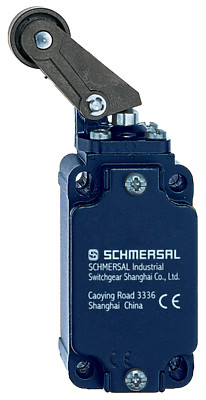
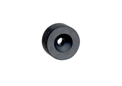
Produktbild (Katalogeinzelphoto )
ID: kbn85f04
| 227,6 kB | .jpg | 352.778 x 130.528 mm - 1000 x 370 Pixel - 72 dpi
| 28,7 kB | .png | 74.083 x 27.517 mm - 210 x 78 Pixel - 72 dpi
| 198,5 kB | .jpg | 352.778 x 130.528 mm - 1000 x 370 Pixel - 72 dpi
| 24,7 kB | .png | 74.083 x 27.517 mm - 210 x 78 Pixel - 72 dpi
| 24,7 kB | .png | 74.083 x 27.517 mm - 210 x 78 Pixel - 72 dpi
Maßzeichnung Grundgerät
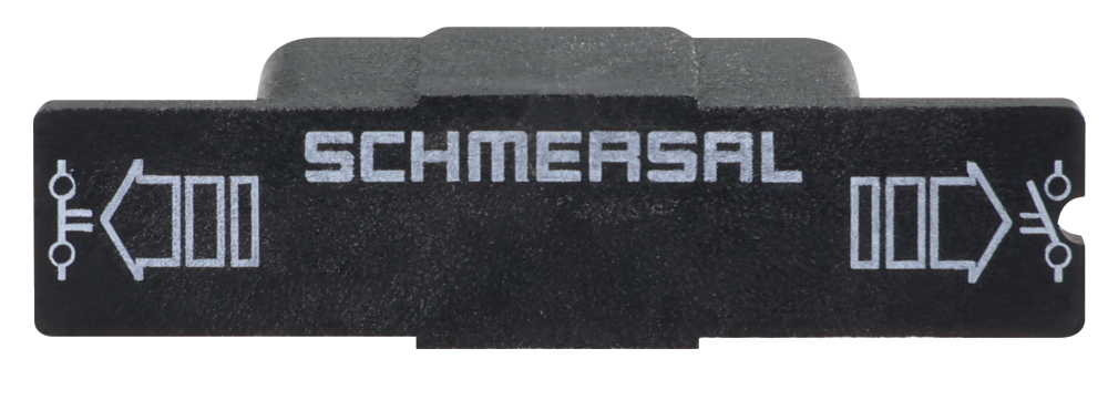
Kontaktbild
Kennliniendiagramm

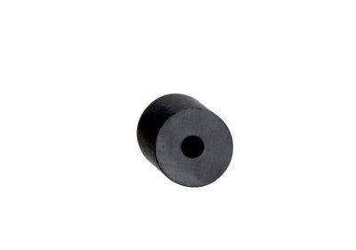
101054816 BP 8
- Unenclosed
- S-pole marked red
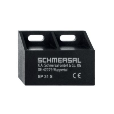
101057521 BP 31 S
- thermoplastic enclosure
- S-pole marked red
- Suitable for mounting on ferrous material with a distance of 20 mm
101057531 BP 10
- Unenclosed
- Colour coding of poles by lables
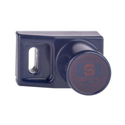
101057532 BP 12 S
- -metal housing
- S-pole marked red
- Suitable for mounting on ferrous material
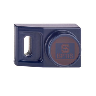
101057533 BP 11 S
- -metal housing
- S-pole marked red
- Suitable for mounting on ferrous material
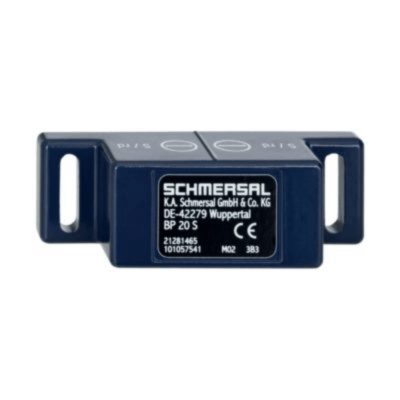
101057541 BP 20 S
- -metal housing
- S-pole marked red
- Suitable for mounting on ferrous material with a distance of 20 mm
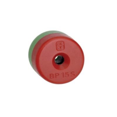
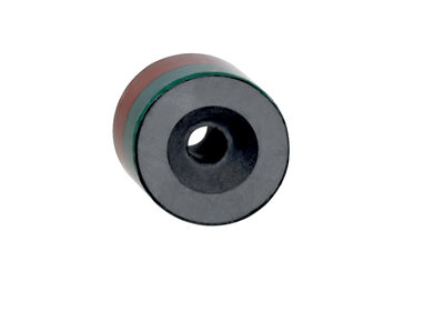
101060163 BP 15
- thermoplastic enclosure
- N-pole marked green
- S-pole marked red
- Suitable for mounting on ferrous material with a distance of 18 mm
101091837 BP 6
- Unenclosed
- S-pole marked red
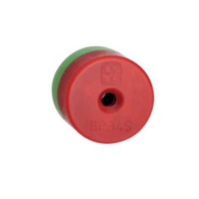
151057553 BP34
- thermoplastic enclosure
- S-pole marked red
- N-pole marked green
- Suitable for mounting on ferrous material with a distance of 25 mm
Schmersal India Pvt. Ltd., Plot No - G-7/1, Ranjangaon MIDC, Tal. - Shirur, Dist.- Pune 412 220
Die genannten Daten und Angaben wurden sorgfältig geprüft. Abbildungen können vom Original abweichen. Weitere technische Daten finden Sie in der Betriebsanleitung. Technische Änderungen und Irrtümer vorbehalten.
Generiert am: 22.09.2025, 18:40
Zuletzt angesehen