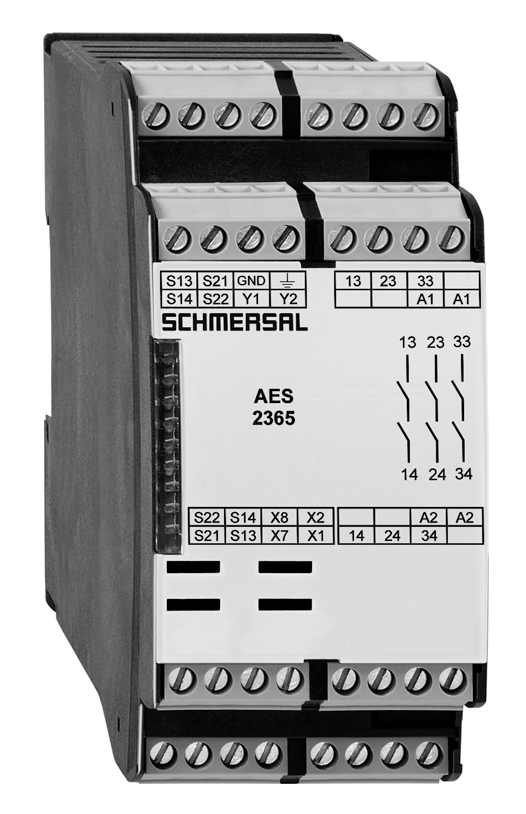
AES 2365 UE: 24...230V AC/DC

AES 2365 UE: 24...230V AC/DC
| Produkt-Typbezeichnung: AES 2(1)6(2) |
| (1) | |
| 3 | 3 Freigabepfade |
| 215 | 5 Freigabepfade |
| (2) | |
| 215 | ohne Anlauftestung |
| 6 | mit Anlauftestung |
- Monitoring of BNS range magnetic safety sensors
- 3 safety contacts, STOP 0
- 2 Signalling outputs
Ordering data
| Note (Delivery capacity) |
Auslaufprodukt |
| Product type description |
AES 2365 UE: 24...230V AC/DC |
| Article number (order number) |
101181686 |
| EAN (European Article Number) |
4030661323169 |
| eCl@ss number, version 12.0 |
27-37-18-19 |
| eCl@ss number, version 11.0 |
27-37-18-19 |
| eCl@ss number, version 9.0 |
27-37-18-19 |
| ETIM number, version 7.0 |
EC001449 |
| ETIM number, version 6.0 |
EC001449 |
| Notice |
Auslaufprodukt |
Approvals - Standards
| Certificates |
cULus |
General data
| Standards |
BG-GS-ET-14 BG-GS-ET-20 EN IEC 62061 EN IEC 60947-5-1 EN IEC 60947-5-3 EN IEC 60947-5-5 EN IEC 61508 EN IEC 60204-1 EN IEC 60947-1 |
| Climatic stress |
EN 60068-2-3 BG-GS-ET-14 |
| Housing material |
Kunststoff, glasfaserverstärkter Thermoplast |
| Gross weight |
310 g |
General data - Features
| Wire breakage detection |
Ja |
| Cross-circuit detection |
Ja |
| Feedback circuit |
Ja |
| Automatic reset function |
Ja |
| Reset after disconnection of supply voltage |
Ja |
| Integral system diagnostics, status |
Ja |
| Number of LEDs |
1 |
| Number of normally closed (NC) |
2 |
| Number of normally open (NO) |
2 |
| Number of undelayed semi-conductor outputs with signaling function |
2 |
| Number of safety contacts |
3 |
| Number of signalling outputs |
2 |
| Safety classification |
| Vorschriften |
EN ISO 13849-1 EN IEC 61508 |
| Stop-Category |
0 |
| Safety classification - Relay outputs |
| Performance Level, up to |
d |
| Category |
3 |
| PFH value |
1,00 x 10⁻⁷ /h |
| Notice |
bis max. 50.000 Schaltzyklen/Jahr und bei max. 80% Kontaktlast |
| Safety Integrity Level (SIL), suitable for applications in |
2 |
| Mission time |
20 Year(s) |
Mechanical data
| Mechanical lifetime, minimum |
20.000.000 Operations |
| Mounting |
Schnellbefestigung für Normschiene nach DIN EN 60715 |
Mechanical data - Connection technique
| Terminal designations |
IEC/EN 60947-1 |
| Cable section, minimum |
0,25 mm² |
| Cable section, maximum |
2,5 mm² |
| Tightening torque of Clips |
0,6 Nm |
| Allowed type of cable |
Starr eindrähtig Flexibel |
| Terminal (mechanical) |
1000075113 |
Mechanical data - Dimensions
| Width |
45 mm |
| Height |
100 mm |
| Depth |
121 mm |
Ambient conditions
| Degree of protection of the enclosure |
IP40 |
| Degree of protection of the installation space |
IP54 |
| Degree of protection of clips or terminals |
IP20 |
| Ambient temperature |
+0 ... +55 °C |
| Storage and transport temperature |
-25 ... +70 °C |
| Resistance to vibrations |
10 ... 55 Hz, Amplitude 0,35 mm, ± 15 % |
| Restistance to shock |
30 g / 11 ms |
Ambient conditions - Insulation values
| Rated impulse withstand voltage Uimp |
4 kV |
| Overvoltage category |
III |
| Degree of pollution |
2 |
Electrical data
| Frequency range |
50 Hz 60 Hz |
| Type of voltage range |
AC DC |
| Thermal test current |
6 A |
| Rated operating voltage |
24 ... 230 VAC |
| Rated AC voltage for controls, 50 Hz, minimum |
20.4 VAC |
| Rated control voltage at AC 50 Hz, maximum |
253 VAC |
| Rated AC voltage for controls, 60 Hz, minimum |
20.4 VAC |
| Rated control voltage at AC 60 Hz, maximum |
253 VAC |
| Rated AC voltage for controls at DC minimum |
20,4 VDC |
| Rated control voltage at DC, maximum |
253 VDC |
| Electrical power consumption |
5 W |
| Contact resistance, maximum |
0,1 Ω |
| Note (Contact resistance) |
in Neuzustand |
| Drop-out delay in case of power failure, typically |
80 ms |
| Drop-out delay in case of emergency, typically |
20 ms |
| Pull-in delay at automatic start, maximum, typically |
100 ms |
| Pull-in delay at RESET, typically |
20 ms |
| Material of the contacts, electrical |
Ag-Ni 10 und 0,2 µm vergoldet |
Electrical data - Safe relay outputs
| Voltage, Utilisation category AC-15 |
230 VAC |
| Current, Utilisation category AC-15 |
3 A |
| Voltage, Utilisation category DC-13 |
24 VDC |
| Current, Utilisation category DC-13 |
2 A |
| Switching capacity, minimum |
10 VDC |
| Switching capacity, minimum |
10 mA |
| Switching capacity, maximum |
250 VAC |
| Switching capacity, maximum |
8 A |
Electrical data - Digital inputs
| Input signal, HIGH Signal "1" |
10 … 30 VDC |
| Input signal, LOW Signal "0" |
0 … 2 VDC |
| Conduction resistance, maximum |
40 Ω |
Electrical data - Digital Output
| Voltage, Utilisation category DC-12 |
24 VDC |
| Current, Utilisation category DC-12 |
0,1 A |
Electrical data - Relay outputs (auxiliary contacts)
| Switching capacity, maximum |
24 VDC |
| Switching capacity, maximum |
2 A |
Electrical data - Electromagnetic compatibility (EMC)
| EMC rating |
EMV-Richtlinie |
Integral system diagnosis (ISD)
| Note (ISD -Faults) |
Folgende Fehler werden von dem Sicherheitsbaustein erkannt und durch ISD angezeigt. |
| Faults |
Nicht-Anziehen oder Nicht-Abfallen der Sicherheitsrelais Nicht-Öffnen oder Nicht-Schließen der Türkontakte Quer- oder Kurzschlüsse an den Schalterleitungen Unterbrechung der Schalterleitungen Fehler an den Eingangsschaltungen oder an den Relaisansteuerungen des Sicherheitsbausteins |
Other data
| Note (applications) |
Sicherheits-Sensor Schutzeinrichtung |
Note
| Note (General) |
Induktive Verbraucher (Schütze, Relais etc.) sind durch eine geeignete Beschaltung zu entstören. |
Wiring example
| Note (Wiring diagram) |
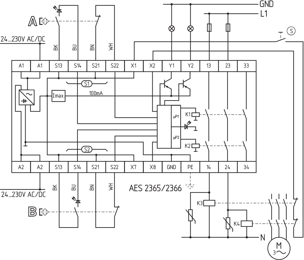
Das Schaltungsbeispiel ist bei geschlossenen Schutzeinrichtungen und im spannungslosen Zustand dargestellt. Überwachung von 2 Schutzeinrichtung(en) mit je einem magnetischen Sicherheits-Sensor der Reihe BNS Zur Absicherung einer Schutzeinrichtung bis zu PL d und Kategorie 3 Die ISD-Tabellen (Integrierte System-Diagnose) zur Analyse der Fehlermeldungen und ihrer Ursachen sind im Anhang aufgeführt. Start-Taster (S): Ein Start-Taster (Schließer) kann optional in den Rückführkreis eingebunden werden. Bei geschlossener Schutzeinrichtung schließen die Sicherheitskontakte erst, wenn der Start-Taster betätigt wurde. Verlängerung der Freigabeverzugszeit: Durch Brücken der Klemmen X7 und X8 kann die Freigabeverzugszeit von 0,1 s auf 1 s eingestellt werden. Wird weder ein Start-Taster noch ein Rückführkreis angeschlossen, müssen X1 und X2 gebrückt werden. |
Sprachfilter
Datenblatt
Betriebsanleitung und Konformitätserklärung
UL-Zertifikat
Schaltungsbeispiel (elektr. Verdrahtung)
Kraftwegdiagramm
SISTEMA-VDMA Bibliothek/Library
Download der aktuellen Version von Adobe Reader
Produktbild (Katalogeinzelphoto )
Produktbild (Katalogeinzelphoto )
Schaltungsbeispiel

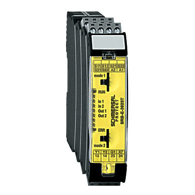
103009973 SRB-E-204ST
- Plug-in screw terminals with coding
- STOP 0 Function
- Monitoring of 4 sensors
- Start button / Auto-start
- 2 Safety outputs
- 4 Signalling outputs
103041495 SRB-E-302ST
- Monitoring of 2 sensors STOP 0
- 1 oder 2-channel control
- Start button / Auto-start
- 2 Safety contacts, 1 Safety Output
- 2 Signalling outputs
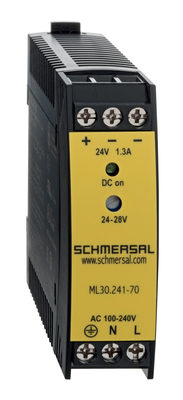
103015923 ML30.241-70
- 1-phase DIN rail power supplies
- AC 100-240V Wide-range input
- DC Output 24-28VDC / 1,3-1,1A / 30W
- Efficiency up to 89,4%
- Width only 22,5mm
| EU-Konformitätserklärung |  |
| Original | K.A. Schmersal GmbH & Co. KG Möddinghofe 30 42279 Wuppertal Germany Internet: www.schmersal.com |
| Erklärung: | Hiermit erklären wir, dass die nachfolgend aufgeführten Bauteile aufgrund der Konzipierung und Bauart den Anforderungen der unten angeführten Europäischen Richtlinien entsprechen. |
| Bezeichnung des Bauteils: | AES 1135/1136 AES 1165/1165-2250 AES 1235/1236 AES 1265/1265-2250 AES 2135 AES 2335/2365 AES 2535 |
| Typ: | siehe Typenschlüssel |
| Beschreibung des Bauteils: | Sicherheitsauswertung |
| Einschlägige Richtlinien: | Maschinenrichtlinie | 2006/42/EG |
| EMV-Richtlinie | 2014/30/EU | |
| RoHS-Richtlinie | 2011/65/EU |
| Angewandte Normen: | DIN EN 60947-5-1:2018 DIN EN ISO 13849-1:2016 DIN EN ISO 13849-2:2013 |
| Benannte Stelle für die Zertifizierung des QS-Systems nach Anhang X, 2006/42/EG: | TÜV Rheinland Industrie Service GmbH Am Grauen Stein, 51105 Köln Kenn-Nr.: 0035 |
| Bevollmächtigter für die Zusammenstellung der technischen Unterlagen: | Oliver Wacker Möddinghofe 30 42279 Wuppertal |
| Ort und Datum der Ausstellung: | Wuppertal, 31. Januar 2024 |
 |
| Rechtsverbindliche Unterschrift Philip Schmersal Geschäftsführer |
Schmersal India Pvt. Ltd., Plot No - G-7/1, Ranjangaon MIDC, Tal. - Shirur, Dist.- Pune 412 220
Die genannten Daten und Angaben wurden sorgfältig geprüft. Abbildungen können vom Original abweichen. Weitere technische Daten finden Sie in der Betriebsanleitung. Technische Änderungen und Irrtümer vorbehalten.
Generiert am: 29.08.2025, 21:51