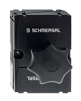
AZ 17-11ZRK-ST
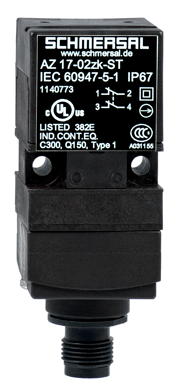
AZ 17-11ZRK-ST
| Product type description: AZ 17-(1)Z(2)K-(3)-(4)-(5) |
| (1) | |
| 11 | 1 NO contacts/1 NC contact |
| 02 | 2 NC contact |
| (2) | |
| without | Latching force 5 N |
| R | Latching force 30 N |
| (3) | |
| without | M16 cable gland |
| 2243 | Front cable entry |
| 2243-1 | Rear cable entry |
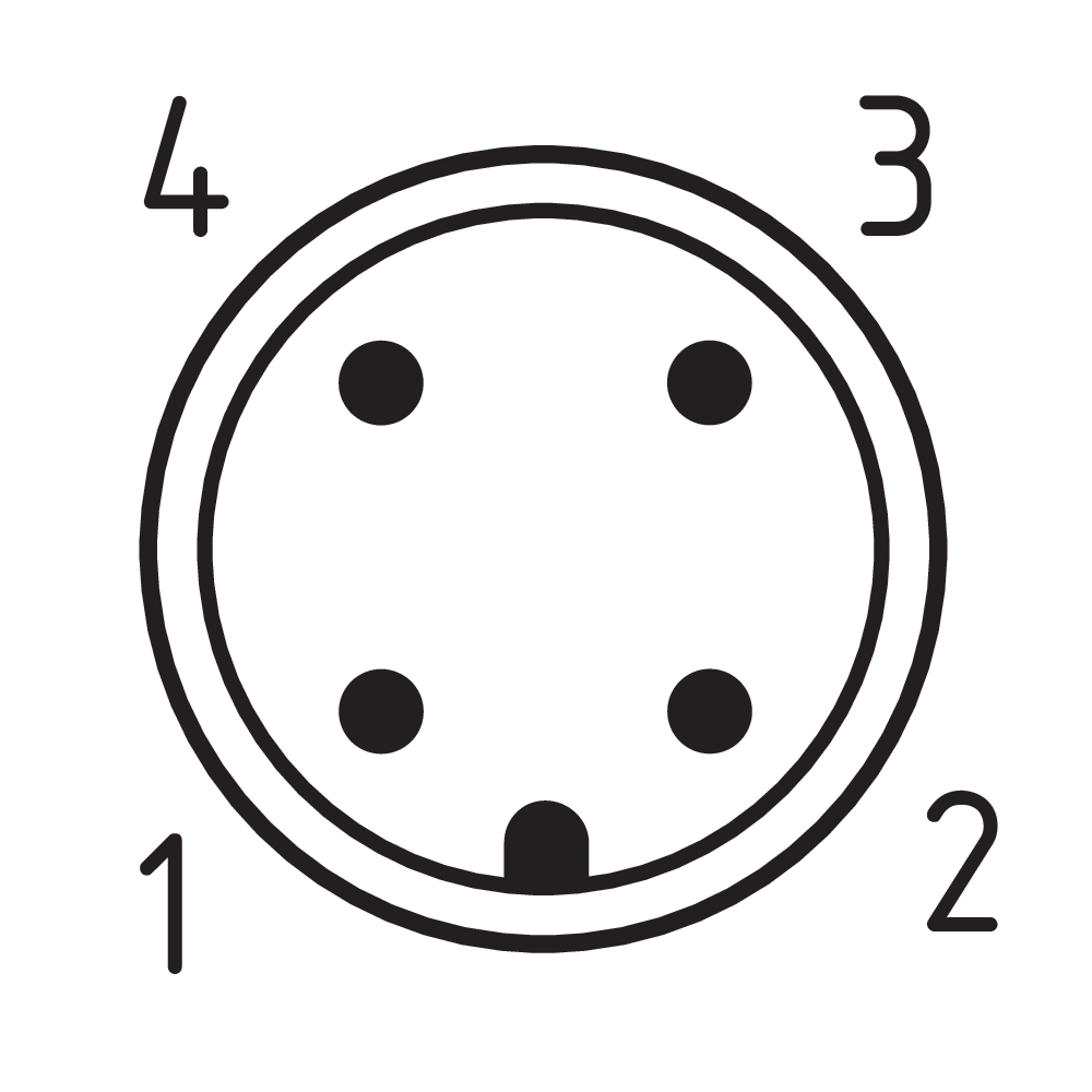
| ST | M12 connector, 4 pole |
| (4) | |
| 1637 | Gold-plated contacts |
| (5) | |
| 5M | Cable length 5 m |
| 6M | Cable length 6 m |
- Connector M12 x 1, 4-pole
- 30 mm x 78.5 mm x 30 mm
- Thermoplastic enclosure
- Double-insulated
- Long life
- small body
- Universal coding
- High level of contact reliability with low voltages and currents
- Insensitive to soiling
- 8 actuating planes
Ordering data
| Product type description |
AZ 17-11ZRK-ST |
| Article number (order number) |
101140774 |
| EAN (European Article Number) |
4030661119731 |
| eCl@ss number, version 12.0 |
27-27-26-02 |
| eCl@ss number, version 11.0 |
27-27-26-02 |
| eCl@ss number, version 9.0 |
27-27-26-02 |
| ETIM number, version 7.0 |
EC002592 |
| ETIM number, version 6.0 |
EC002592 |
Approvals - Standards
| Certificates |
BG cULus CCC |
General data
| Standards |
EN ISO 13849-1 EN ISO 14119 EN IEC 60947-5-1 |
| Coding level according to EN ISO 14119 |
Low |
| Working principle |
electromechanical |
| Housing material |
Plastic, glass-fibre reinforced thermoplastic, self-extinguishing |
| Gross weight |
85 g |
General data - Features
| Increased latching force |
Yes |
| Number of actuating directions |
2 |
| Number of auxiliary contacts |
1 |
| Number of safety contacts |
1 |
| Number of cable glands |
1 |
| Safety classification |
| Standards |
EN ISO 13849-1 |
| Performance Level, up to |
c |
| Category |
1 |
| B10D Normally-closed contact (NC) |
2,000,000 Operations |
| Note |
Electrical life on request. |
| B10D Normally-open contact (NO) |
1,000,000 Operations |
| Note |
at 10% Ie and ohmic load |
| Mission time |
20 Year(s) |
| Safety classification - Fault exclusion |
| Please note: |
Can be used when fault exclusion for dangerous damage to the 1-channel mechanism is permissible and sufficient protection against manipulation is guaranteed. |
| Performance Level, up to |
d |
| Category |
3 |
| Note |
for 2-channel use and with suitable logic unit. |
| Mission time |
20 Year(s) |
Mechanical data
| Mechanical life, minimum |
1,000,000 Operations |
| Latching force |
30 N |
| Positive break travel |
11 mm |
| Positive break force per NC contact, minimum |
17 N |
| Actuating speed, maximum |
2 m/s |
| Mounting |
Screws |
| Type of the fixing screws |
2x M5 |
Mechanical data - Connection technique
| Termination |
Connector plug M12, 4-pole, (A-coding) |
Mechanical data - Dimensions
| Length of sensor |
30 mm |
| Width of sensor |
30 mm |
| Height of sensor |
78.5 mm |
Ambient conditions
| Degree of protection |
IP67 |
| Ambient temperature |
-30 ... +80 °C |
| Storage and transport temperature |
-30 ... +85 °C |
| Permissible installation altitude above sea level, maximum |
2,000 m |
Ambient conditions - Insulation values
| Rated insulation voltage Ui |
250 VAC |
| Rated impulse withstand voltage Uimp |
4 kV |
| Overvoltage category |
III |
| Degree of pollution |
3 |
| Rated impulse withstand voltage, connector 4-pole |
2.5 kV |
Electrical data
| Thermal test current |
10 A |
| Required rated short-circuit current |
1,000 A |
| Switching element |
NO contact, NC contact |
| Switching principle |
slow action, positive break NC contact |
| Maximum switching frequency |
2,000 /h |
| Material of the contacts, electrical |
Silver |
Electrical data - Safety contacts
| Voltage, Utilisation category AC-15 |
230 VAC |
| Current, Utilisation category AC-15 |
4 A |
| Voltage, Utilisation category DC-13 |
24 VDC |
| Current, Utilisation category DC-13 |
4 A |
| Note, Utilisation category DC-13 |
Connector 4-pole |
Electrical data - Auxiliary contacts
| Voltage, Utilisation category AC-15 |
230 VAC |
| Current, Utilisation category AC-15 |
4 A |
| Voltage, Utilisation category DC-13 |
24 VDC |
| Current, Utilisation category DC-13 |
4 A |
| Note, Utilisation category DC-13 |
Connector 4-pin |
Other data
| Note (applications) |
sliding safety guard removable guard hinged safety guard |
Scope of delivery
| Scope of delivery |
Actuator must be ordered separately. Slot cover for dust-proof covering of the opening not in use |
Note
| Note (General) |
Individual coding available on request |
Language filter
Datasheet
CCC certification
BG-test certificate
UL Certificate
SISTEMA-VDMA library
Download the latest version of Adobe Reader
Product picture (catalogue individual photo)
Dimensional drawing basic component

Switch travel diagram

Diagram
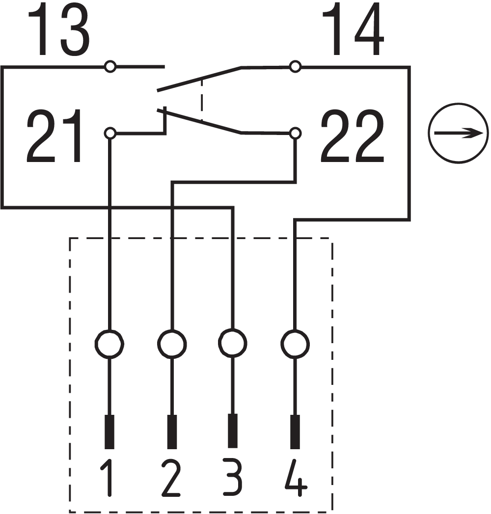
Contact arrangement
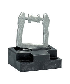
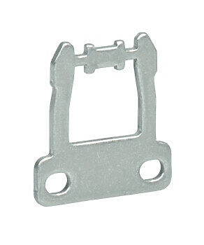
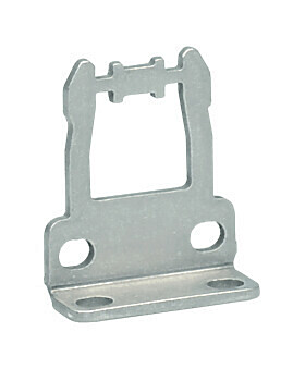
101126060 ACTUATOR AZ 17-B6
- For very smal actuating radii
- The direction of actuation can be selected by applicable insertion of the insert
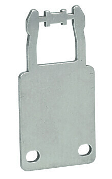
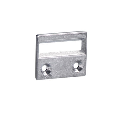
101122893 ACTUATOR AZ 17/170-B1
- Particularly suitable for sliding doors
- Straight actuator
- Particularly suitable for sliding doors
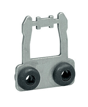
101137406 ACTUATOR AZ 17/170-B1-2245
- Straight actuator with rubber mounting
- Damps vibration on guard device
- Particularly suitable for sliding doors
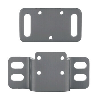
101139788 ACTUATOR AZ 17/170-B11
- Particularly suitable for sliding doors
101139789 ACTUATOR AZ 17/170-B15
- Particularly suitable for sliding doors
- Particularly suitable for sliding doors
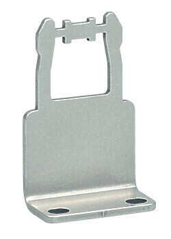
101122895 ACTUATOR AZ 17/170-B5
- Particularly suitable for sliding doors
Schmersal Ltd., Sparrowhawk Close, WR14 1GL Malvern
The details and data referred to have been carefully checked. Images may diverge from original. Further technical data can be found in the manual. Technical amendments and errors possible.
Generated on: 25/04/2024, 04:18