EX-BNS 40S-12ZG
EX-BNS 40S-12ZG
| Product type description: EX-BNS40S-12Z(1)-(2) |
| (1) | |
| without | without LED switching conditions display |
| G | with LED switching conditions display |
| (2) | |
| without | With countersunk mounting holes |
| C | concealed threaded holes on the back |
- LED version
- Explosion protection for ATEX Zones 2 and 22
- Stainless steel enclosure
- 88 mm x 27 mm x 14,5 mm
- Concealed mounting possible
- Insensitive to transverse misalignment
- no mechanical wear
- Suitable for food processing industry
- Cable connection suitable for the food industry
Ordering data
| Product type description |
EX-BNS 40S-12ZG |
| Article number (order number) |
103002171 |
| EAN (European Article Number) |
4030661428444 |
| eCl@ss number, version 12.0 |
27-27-44-01 |
| eCl@ss number, version 11.0 |
27-27-24-02 |
| eCl@ss number, version 9.0 |
27-27-24-02 |
| ETIM number, version 7.0 |
EC002544 |
| ETIM number, version 6.0 |
EC002544 |
Explosion protection
| Explosion protection: regulations |
EN IEC 60079-0 EN IEC 60079-15 EN 60079-31 |
| Explosion protection zones |
2 22 |
| Explosion protection category |
3G 3D |
| Explosion protection designation |
D II 3G Ex nA nC IIC T6 Gc D II 3D Ex tc IIIC T80°C Dc X |
Manufacturer declaration |
ATEX Zone 2 and 22 |
General data
| Standards |
BG-GS-ET-14 EN IEC 60947-5-3 |
| Housing construction form |
Block |
| Installation conditions (mechanical) |
not flush |
| Housing material |
Stainless steel (V4A) |
| Gross weight |
200 g |
General data - Features
| Coding |
Yes |
| Short circuit detection |
Yes |
| Cross-circuit detection |
Yes |
| Integral system diagnostics, general |
Yes |
| Prerequisite evaluation unit |
Yes |
| Number of normally closed (NC) |
2 |
| Number of normally open (NO) |
1 |
| Safety classification |
| Standards |
EN ISO 13849-1 |
| Mission time |
20 Year(s) |
Safety classification - Safety outputs
| B10D- Value Normally-closed contact/Normally open contact (NC/NO) |
25,000,000 Operations |
Mechanical data
| Active area |
lateral |
| Actuating element |
Magnet |
| Impact energy, maximum |
7 J |
| Direction of motion |
Head-on to the active surface |
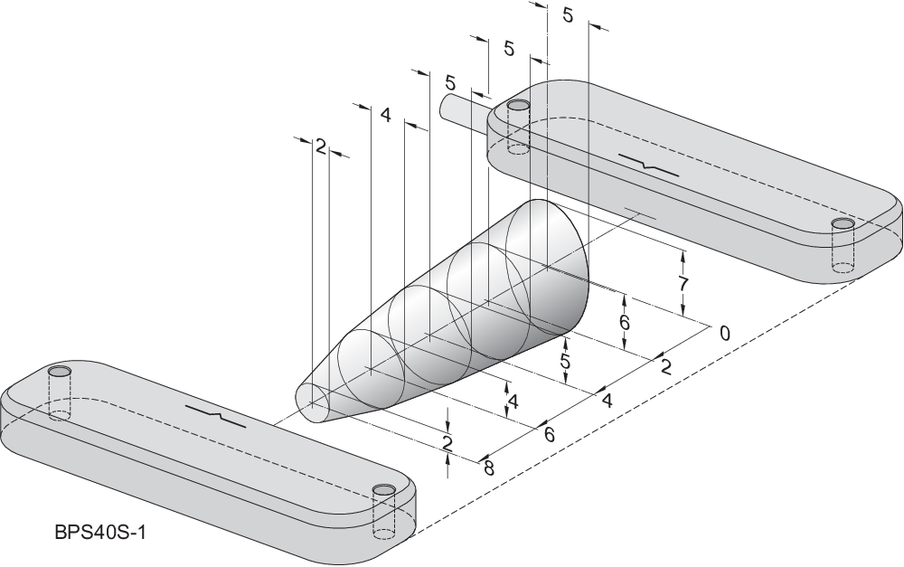
Mechanical data - Switching distances according EN IEC 60947-5-3
| Assured switching distance "ON" Sao |
8 mm |
| Assured switching distance "OFF" Sar |
18 mm |
Mechanical data - Connection technique
| Length of cable |
1 m |
| Termination |
Cable |
| Wire cross-section |
0.25 mm2 |
| Wire cross-section |
23 AWG |
| Material of the Cable mantle |
LiYY |
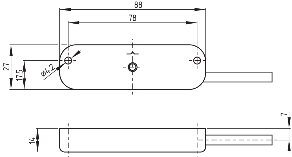
Mechanical data - Dimensions
| Length of sensor |
14.5 mm |
| Width of sensor |
88 mm |
| Height of sensor |
27 mm |
Ambient conditions
| Degree of protection |
IP65 IP67 |
| Ambient temperature |
-20 ... +60 °C |
| Storage and transport temperature |
-25 ... +80 °C |
| Resistance to vibrations |
10 … 55 Hz, amplitude 1 mm |
| Restistance to shock |
30 g / 11 ms |
Electrical data
| Required rated short-circuit current |
100 A |
| Switching voltage, maximum |
24 VDC |
| Switching current, maximum |
0.01 A |
| Switching capacity, maximum |
0.24 W |
| Switching frequency, maximum |
5 Hz |
Electrical data - Digital Output
| Design of control elements |
Miscellaneous, Reed contacts |
Status indication
| Note (Integral System Diagnostics, status ) |
The LED is illuminated when the guard is closed. |
Scope of delivery
| Scope of delivery |
Actuator must be ordered separately. |
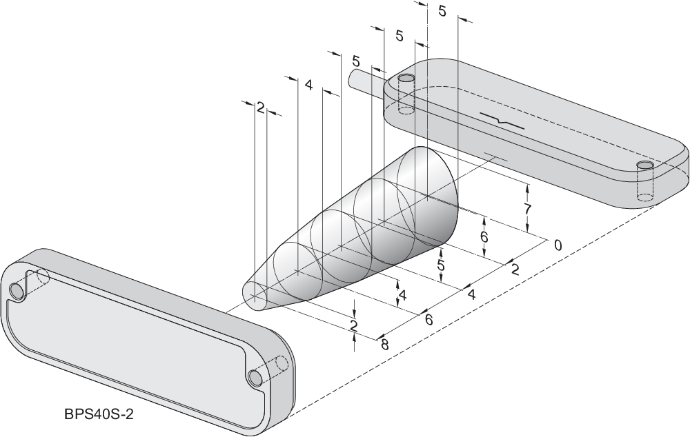
Accessory
| Recommendation (actuator) |
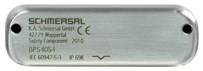
BPS 40S-2 BPS 40S-1-C BPS 40S-2-C |
| Recommended safety switchgear |
SRB-E-301ST SRB-E-201LC |
Note
| Note (General) |
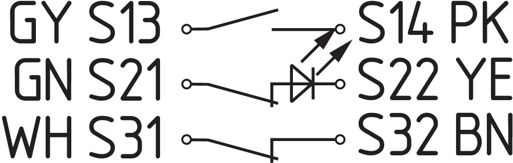
Contact symbols shown for the closed condition of the guard device. The contact configuration for versions with or without LED is identical. |
Wiring example
| Note (Wiring diagram) |
Contact S21-S22 must be integrated in the safety circuit. |
Language filter
Datasheet
Operating instructions and Declaration of conformity
SISTEMA-VDMA library
Download the latest version of Adobe Reader
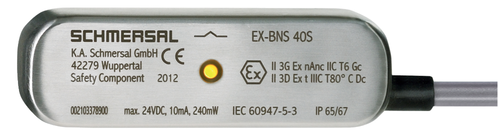
Product picture (catalogue individual photo)
Dimensional drawing basic component
Diagram
Characteristic curve
Characteristic curve

Schmersal Ltd., Sparrowhawk Close, WR14 1GL Malvern
The details and data referred to have been carefully checked. Images may diverge from original. Further technical data can be found in the manual. Technical amendments and errors possible.
Generated on: 25/04/2024, 10:01