This document provides all the information you need for the mounting, set-up and commissioning to ensure the safe operation and disassembly of the switchgear. The operating instructions enclosed with the device must always be kept in a legible condition and accessible.
All operations described in the operating instructions manual must be carried out by trained specialist personnel, authorised by the plant operator only.
Please make sure that you have read and understood these operating instructions and that you know all applicable legislations regarding occupational safety and accident prevention prior to installation and putting the component into operation.
The machine builder must carefully select the harmonised standards to be complied with as well as other technical specifications for the selection, mounting and integration of the components.
The information contained in this operating instructions manual is provided without liability and is subject to technical modifications.
The Schmersal range of products is not intended for private consumers.
The products described in these operating instructions are developed to execute safety-related functions as part of an entire plant or machine. It is the responsibility of the manufacturer of a machine or plant to ensure the correct functionality of the entire machine or plant.
The safety switchgear must be exclusively used in accordance with the versions listed below or for the applications authorised by the manufacturer. Detailed information regarding the range of applications can be found in the chapter "Product description".
The user must observe the safety instructions in this operating instructions manual, the country specific installation standards as well as all prevailing safety regulations and accident prevention rules.
| Product type description: AZ 16-(1)ZV(2)K-(3)-(4)-(5) |
| (1) | |
| without | 1 NO contacts/1 NC contact |
| 02 | 2 NC contact |
| 03 | 3 NC contact |
| 12 | 1 NO contact/2 NC contacts |
| (2) | |
| without | Ejection force |
| R | Latching force 30 N |
| (3) | |
| G24 | with LED (only available for version with one NO and one NC contact) |
| (4) | |
| M16 | cable entry M16 |
| M20 | Cable entry M20 |
| ST | Connector M12, 4 pole, bottom |
| STL | Connector M12, 4 pole, left |
| STR | Connector M12, 4 pole, right |
| (5) | |
| 2254 | Latching force 5 N |
| 1762 | Front mounting |
| 1637 | Gold-plated contacts |
For special versions, which are not listed in the ordering code, these specifications apply accordingly, provided that they correspond to the standard version.
The safety switches with separate actuator are suitable for sliding, hinged and removable safety guards, which need to be closed in order to ensure the necessary operational safety.
The safety switches are used for applications, in which the hazardous situation is terminated without delay when the safety guard is opened.
When the safety guard is opened, the NC contacts are positively opened and the NO contacts are closed.
We shall accept no liability for damages and malfunctions resulting from defective mounting or failure to comply with the operating instructions manual. The manufacturer shall accept no liability for damages resulting from the use of unauthorised spare parts or accessories.
For safety reasons, invasive work on the device as well as arbitrary repairs, conversions and modifications to the device are strictly forbidden, the manufacturer shall accept no liability for damages resulting from such invasive work, arbitrary repairs, conversions and/or modifications to the device.
| Certificates |
TÜV cULus CCC |
| Standards |
EN ISO 13849-1 EN ISO 14119 EN IEC 60947-5-1 |
| Coding level according to EN ISO 14119 |
Low |
| Working principle |
electromechanical |
| Housing material |
Plastic, glass-fibre reinforced thermoplastic, self-extinguishing |
| Gross weight |
115 g |
| Number of actuating directions |
3 |
| Number of auxiliary contacts |
1 |
| Number of safety contacts |
1 |
| Number of cable glands |
3 |
| Safety classification |
| Standards |
EN ISO 13849-1 |
| Performance Level, up to |
c |
| Category |
1 |
| B10D Normally-closed contact (NC) |
2,000,000 Operations |
| Note |
Electrical life on request. |
| B10D Normally-open contact (NO) |
1,000,000 Operations |
| Note |
at 10% Ie and ohmic load |
| Mission time |
20 Year(s) |
| Safety classification - Fault exclusion |
| Please note: |
Can be used when fault exclusion for dangerous damage to the 1-channel mechanism is permissible and sufficient protection against manipulation is guaranteed. |
| Performance Level, up to |
d |
| Category |
3 |
| Note |
for 2-channel use and with suitable logic unit. |
| Mission time |
20 Year(s) |
| Mechanical life, minimum |
1,000,000 Operations |
| Latching force |
5 N |
| Positive break travel |
8 mm |
| Positive break force per NC contact, minimum |
10 N |
| Positive break force, minimum |
10 N |
| Actuating speed, maximum |
2 m/s |
| Mounting |
Screws |
| Type of the fixing screws |
2x M6 |
| Cable entry |
3 x M16 x 1,5 |
| Termination |
Screw terminals |
| Cable section, minimum |
0.25 mm² |
| Cable section, maximum |
2.5 mm² |
| Note |
All indications including the conductor ferrules. |
| Allowed type of cable |
solid single-wire solid multi-wire flexible |
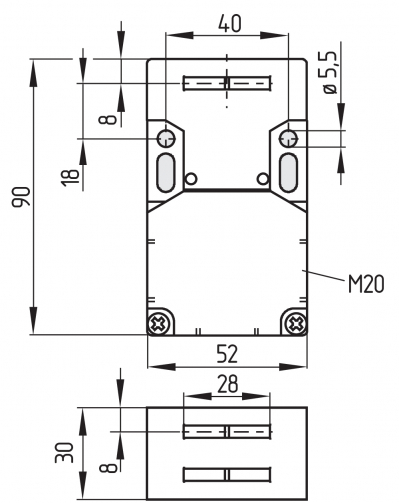
| Length of sensor |
30 mm |
| Width of sensor |
52 mm |
| Height of sensor |
90 mm |
| Degree of protection |
IP67 |
| Ambient temperature |
-30 ... +80 °C |
| Storage and transport temperature |
-40 ... +85 °C |
| Permissible installation altitude above sea level, maximum |
2,000 m |
| Rated insulation voltage Ui |
500 V |
| Rated impulse withstand voltage Uimp |
6 kV |
| Overvoltage category |
III |
| Degree of pollution |
3 |
| Thermal test current |
10 A |
| Required rated short-circuit current |
1,000 A |
| Switching element |
NO contact, NC contact |
| Switching principle |
slow action, positive break NC contact |
| Maximum switching frequency |
4,000 /h |
| Material of the contacts, electrical |
Silver |
| Voltage, Utilisation category AC-15 |
230 VAC |
| Current, Utilisation category AC-15 |
4 A |
| Voltage, Utilisation category DC-13 |
24 VDC |
| Current, Utilisation category DC-13 |
4 A |
| Voltage, Utilisation category AC-15 |
230 VAC |
| Current, Utilisation category AC-15 |
4 A |
| Voltage, Utilisation category DC-13 |
24 VDC |
| Current, Utilisation category DC-13 |
4 A |
Note about the safety classification
Basically suitable up to Cat. 1 / PL c.
With 2-channel usage with fault exclusion mechanism (if a fault exclusion to the 1-channel mechanics is authorised) and suitable logic applicable up to Cat. 3 / PL d

(Determined values can vary depending on the application-specific parameters hop, dop and tcycle as well as the load.)
If multiple safety components are wired in series, the Performance Level to EN ISO 13849-1 will be reduced due to the restricted error detection under certain circumstances.
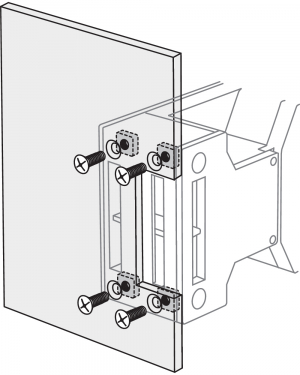
The mounting dimensions are indicated on the rear of the component. The enclosure must not be used as an end stop.
Any mounting position. The mounting position however must be chosen so that the ingress of dirt and soiling in the used opening is avoided. The unused openings must be sealed by means of slot sealing plugs (AZ 15/16 - 1476-1 available as accessory) after fitting.
See operating instructions Actuator.
| Actuating radii [mm] |  |  | ||
|---|---|---|---|---|
| over the small edge of the actuator | over the wide edge of the actuator | |||
| Rmin | d | Rmin | d | |
| AZ 15/16-B2 | - | - | 45 | 11 |
| AZ 15/16-B2-1747 | - | - | 45 | 11 |
| AZ 15/16-B3 | 32 | 11 | - | - |
| AZ 15/16-B3-1747 | 32 | 11 | - | - |
| AZ 15/16-B6 | 25 | 11 | 38 | 11 |
All measurements in mm.
The contact labelling can be found in the wiring compartment of the switch. Appropriate cable glands with a suitable degree of protection are to be used.
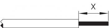
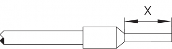
Settle length x of the conductor: 6 mm
After wiring, dust and soiling must be removed from the wiring compartment. The safety switch is double insulated. The use of a protective ground connector therefore is not authorised.
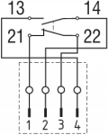
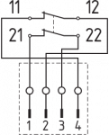
Contacts are shown with safety guard closed. All NC contacts have positive break B.
| AZ 16ZV.K | AZ 16-02ZV.K | AZ 16-12ZV.K |
|---|---|---|
 |  |  |
| AZ 16-03ZV.K | AZ 16ZV.K-ST | AZ 16-02ZV.K-ST |
|---|---|---|
 |  |  |
| AZ 16-12ZV.K-ST | LED | LED |
|---|---|---|
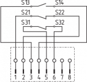 | 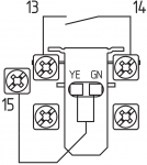 | 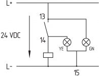 |
| Key | |
|---|---|
| B | Automatic opener, NC contact |
 | Normally-open contact |
 | Normally-closed contact |
The safety function of the safety components must be tested. In the case of correct installation and adequate use, the safety switchgear features maintenance-free functionality. A regular visual inspection and functional test, including the following steps, is recommended:
The safety switchgear must be disassembled in a de-energised condition only.