SRB200EXi-1A
SRB200EXi-1A
Downloads
- Automatic reset function
- 2 safety contacts
- Suitable for signal processing of emergency stop control devices, interlocking equipment, etc
Ordering data
| Product type description |
SRB200EXi-1A |
| Article number (order number) |
103037577 |
| EAN (European Article Number) |
4030661544939 |
| eCl@ss number, version 12.0 |
27-37-18-19 |
| eCl@ss number, version 11.0 |
27-37-18-19 |
| eCl@ss number, version 9.0 |
27-37-18-19 |
| ETIM number, version 7.0 |
EC001449 |
| ETIM number, version 6.0 |
EC001449 |
Explosion protection
| Explosion protection: regulations |
EN IEC 60079-0 EN 60079-11 EN IEC 60079-15 |
| Explosion protection zones |
2 |
| Explosion protection category |
3G |
| Explosion protection designation |
D II 3 G Ex nA nC IIC T5 Gc (Installation SRB, in Zone 2) D II (2) G [Ex ib Gb] IIC D II (2) D [Ex ib Db] IIIC |
General data
| Climatic stress |
EN 60068-2-78 |
| Housing material |
Glass-fibre reinforced thermoplastic, ventilated |
| Gross weight |
266 g |
General data - Features
| Wire breakage detection |
Yes |
| Cross-circuit detection |
Yes |
| Earth connection detection |
Yes |
| Integral system diagnostics, status |
Yes |
| Number of LEDs |
5 |
| Number of normally closed (NC) |
2 |
| Number of safety contacts |
2 |
| Safety classification |
| Standards |
EN ISO 13849-1 EN IEC 60947-5-1 EN IEC 61508 |
| Stop-Category |
0 |
| Safety classification - Relay outputs |
| Performance Level, stop 0, up to |
e |
| Category, Stop 0 |
4 |
| Diagnostic Coverage (DC) Level, Stop 0 |
≥ 99 % |
| PFH value, Stop 0 |
2.00 x 10⁻⁸ /h |
| Safety Integrity Level (SIL), Stop 0, suitable for applications in |
3 |
| Mission time |
15 Year(s) |
| Common Cause Failure (CCF), minimum |
65 |
Mechanical data
| Mechanical life, minimum |
10,000,000 Operations |
| Mounting |
Snaps onto standard DIN rail to EN 60715 |
Mechanical data - Connection technique
| Terminal designations |
IEC/EN 60947-1 |
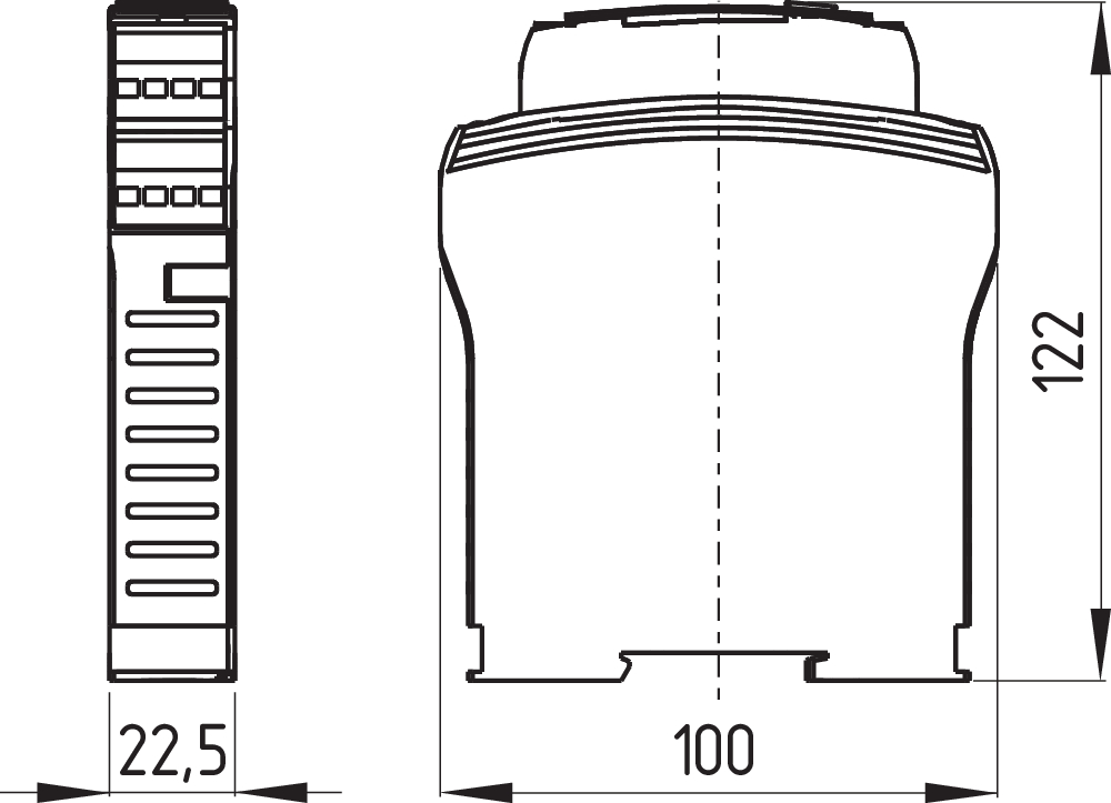
Mechanical data - Dimensions
| Width |
22.5 mm |
| Height |
100 mm |
| Depth |
121 mm |
Ambient conditions
| Degree of protection of the enclosure |
IP40 |
| Degree of protection of the mounting space |
IP54 |
| Degree of protection of clips or terminals |
IP20 |
| Ambient temperature |
-25 ... +60 °C |
| Storage and transport temperature |
-40 ... +85 °C |
| Resistance to vibrations |
10 ... 55 Hz, Amplitude 0.35 mm |
| Restistance to shock |
30 g / 11 ms |
Ambient conditions - Insulation values
| Rated impulse withstand voltage Uimp |
4 kV |
| Overvoltage category |
III |
| Degree of pollution |
2 |
Electrical data
| Operating voltage |
24 VDC -10 % / +20 % |
| Ripple voltage |
10 % |
| Current consumption |
57 mA |
| Rated operating voltage |
24 VDC |
| Rated AC voltage for controls at DC minimum |
20.4 VDC |
| Rated control voltage at DC, maximum |
28.8 VDC |
| Utilisation category AC-15 |
230 VAC |
| Utilisation category AC-15 |
2 A |
| Utilisation category DC-13 |
24 VDC |
| Utilisation category DC-13 |
2 A |
| Contact resistance, maximum |
0.1 Ω |
| Note (Contact resistance) |
in new state |
| Drop-out delay in case of power failure, typically |
20 ms |
| Drop-out delay in case of "emergency stop", maximum |
20 ms |
| Pull-in delay at automatic start, maximum, typically |
300 ms |
| Pull-in delay at RESET, typically |
20 ms |
| Material of the contacts, electrical |
AgSn0. self-cleaning, positive drive |
Electrical data - Digital inputs
| Conduction resistance, maximum |
30 Ω |
Electrical data - Electromagnetic compatibility (EMC)
| EMC rating |
EMC-Directive |
Other data
| Note (applications) |
Safety sensor Guard system Emergency-Stop button Pull-wire emergency stop switches |
Note
| Note (General) |
Inductive loads (e.g. contactors, relays, etc.) are to be suppressed by means of a suitable circuit. |
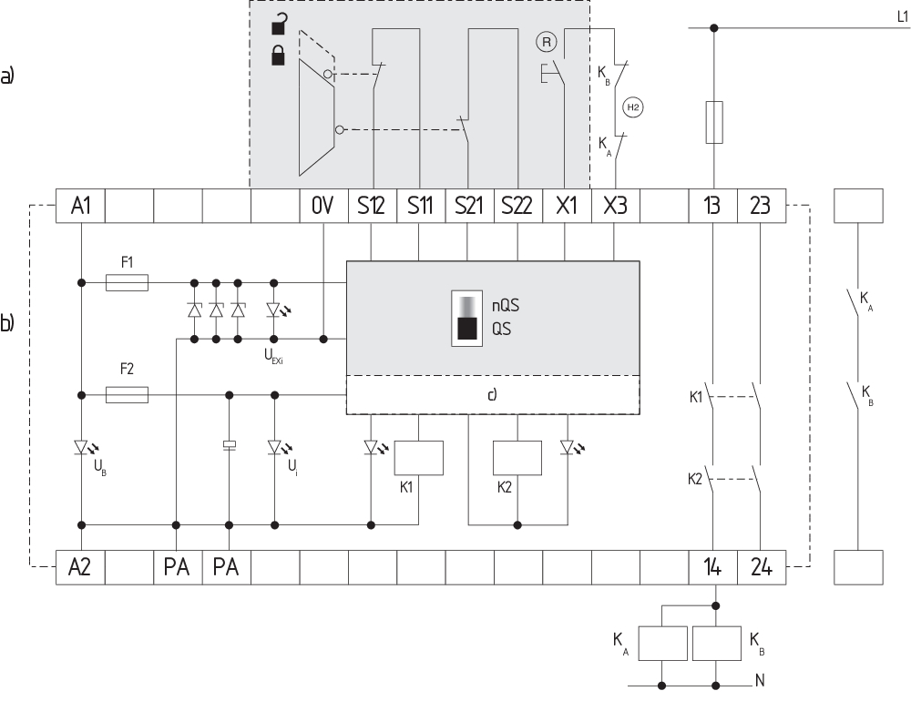
Wiring example
| Note (Wiring diagram) |
The wiring diagram is shown with guard doors closed and in de-energised condition. Monitoring 1 guard door(s), each with a magnetic safety sensor of the BNS range If only one external relay or contactor is used to switch the load, the system can be classified in Control Category 3 to ISO 13849-1, if exclusion of the fault “Failure of the external contactor” can be substantiated and is documented, e.g. by using a reliable down-rated contactor. A second contactor leads to an increase in the level of security by redundant switching to switch the load off. To secure a guard door up to PL e and Category 4 The feedback circuit monitors the position of the contactors KA and KB. Automatic start: The automatic start is programmed by connecting the feedback circuit to the terminals X1/X2. If the feedback circuit is not required, establish a bridge. |
Language filter
Datasheet
Operating instructions and Declaration of conformity
BG-test certificate
INMETRO certification
IECEx certification
Brochure
Download the latest version of Adobe Reader
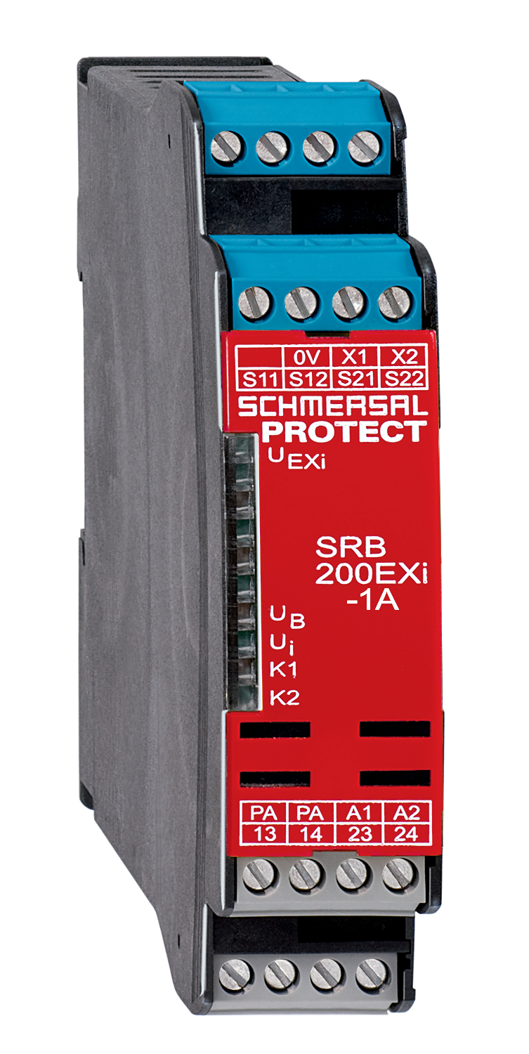
Product picture (catalogue individual photo)
Dimensional drawing basic component
Symbol (technical standard)

Wiring example
| EU-Konformitätserklärung |  |
| Original | K.A. Schmersal GmbH & Co. KG Möddinghofe 30 42279 Wuppertal Germany Internet: www.schmersal.com |
| Erklärung: | Hiermit erklären wir, dass die nachfolgend aufgeführten Bauteile aufgrund der Konzipierung und Bauart den Anforderungen der unten angeführten Europäischen Richtlinien entsprechen. |
| Bezeichnung des Bauteils: | SRB200EXi-1A |
| Typ: | siehe Typenschlüssel |
| Kennzeichnung: | D II 3 (2) G Ex ec nC [ib Gb] IIC T5 Gc D II (2) D [Ex ib Db] IIIC |
| Beschreibung des Bauteils: | Relais-Sicherheitskombination für NOT-HALT-Schaltungen und Schutztürüberwachungen |
| Einschlägige Richtlinien: | Maschinenrichtlinie | 2006/42/EG |
| EMV-Richtlinie | 2014/30/EU | |
| Explosionsschutzrichtlinie (ATEX) | 2014/34/EU | |
| RoHS-Richtlinie | 2011/65/EU |
| Angewandte Normen: | EN IEC 60079-0:2018 EN IEC 60079-7:2015 / A1:2018 EN 60079-11:2012 EN IEC 60079-15:2019 EN 60079-15:2010 EN 60947-5-1:2017 + AC:2020 EN ISO 13849-1:2015 EN ISO 13849-2:2012 |
| Benannte Stelle für die Zertifizierung des QS-Systems nach Anhang X gemäß 2006/42/EG, Anhang IV gemäß 2014/34/EU und für die ATEX-Zertifizierung: | TÜV Rheinland Industrie Service GmbH Am Grauen Stein, 51105 Köln Kenn-Nr.: 0035 |
| Baumusterprüfbescheinigung: | TÜV 22 ATEX 8837 X |
| Dieses Zertifikat bezieht sich nur auf die Zertifizierung der Produkte gem. der Explosionsschutzrichtlinie 2014/34/EU (ATEX). Die Konformität der Produkte gem. der Maschinenrichtlinie 2006/42/EG wird durch den Hersteller in Eigenverantwortung erklärt. |
| Bevollmächtigter für die Zusammenstellung der technischen Unterlagen: | Oliver Wacker Möddinghofe 30 42279 Wuppertal |
| Ort und Datum der Ausstellung: | Wuppertal, 18. Oktober 2023 |
 |
| Rechtsverbindliche Unterschrift Philip Schmersal Geschäftsführer |
Schmersal India Pvt. Ltd., Plot No - G-7/1, Ranjangaon MIDC, Tal. - Shirur, Dist.- Pune 412 220
The details and data referred to have been carefully checked. Images may diverge from original. Further technical data can be found in the manual. Technical amendments and errors possible.
Generated on: 19/04/2024, 8:07 am