AES2285

AES2285
- Multi-evaluation of up to 6 safety guards
- Monitoring of BNS range magnetic safety sensors
- 2 safety contacts, STOP 0
- 6 Signalling outputs
- Additional contacts by means of output expander
- Individual signal outputs for each guard door
Ordering data
| Note (Delivery capacity) |
Phased-out product |
| Product type description |
AES2285 |
| Article number (order number) |
101172211 |
| EAN (European Article Number) |
4250116201846 |
| eCl@ss number, version 12.0 |
27-37-18-19 |
| eCl@ss number, version 11.0 |
27-37-18-19 |
| eCl@ss number, version 9.0 |
27-37-18-19 |
| ETIM number, version 7.0 |
EC001449 |
| ETIM number, version 6.0 |
EC001449 |
| Available until |
31.12.2024 |
General data
| Standards |
BG-GS-ET-14 BG-GS-ET-20 EN IEC 62061 EN ISO 13849-1 EN IEC 60947-5-1 EN IEC 60947-5-3 EN IEC 60947-5-5 EN IEC 61508 EN IEC 60204-1 EN IEC 60947-1 |
| Climatic stress |
EN 60068-2-78 |
| Housing material |
Glass-fibre reinforced thermoplastic, ventilated |
| Gross weight |
430 g |
General data - Features
| Electronic Fuse |
Yes |
| Wire breakage detection |
Yes |
| Cross-circuit detection |
Yes |
| Removable Terminals |
Yes |
| Start input |
Yes |
| Feedback circuit |
Yes |
| Automatic reset function |
Yes |
| Reset edge detection |
Yes |
| Reset after disconnection of supply voltage |
Yes |
| Earth connection detection |
Yes |
| Integral system diagnostics, status |
Yes |
| Number of auxiliary contacts |
1 2 |
| Number of LEDs |
3 |
| Number of undelayed semi-conductor outputs with signaling function |
6 |
| Number of safety contacts |
2 |
| Number of Snap-in contacts, maximum |
6 |
| Number of Snap-in contacts, minimum |
1 |
| Number of signalling outputs |
6 |
| Safety classification |
| Standards |
EN IEC 60947-5-1 EN IEC 61508 |
| Stop-Category |
0 |
| Safety classification - Relay outputs |
| Performance Level, up to |
d |
| Category |
3 |
| Diagnostic Coverage (DC) Level |
≥ 99 % |
| PFH value |
2.00 x 10⁻⁸ /h |
| Safety Integrity Level (SIL), suitable for applications in |
3 |
| Mission time |
20 Year(s) |
| Common Cause Failure (CCF), minimum |
65 |
Mechanical data
| Mechanical life, minimum |
10,000,000 Operations |
| Mounting |
Snaps onto standard DIN rail to EN 60715 |
Mechanical data - Connection technique
| Terminal designations |
IEC/EN 60947-1 |
| Termination |
rigid or flexible Screw terminals M20 x 1.5 |
| Cable section, minimum |
0.25 mm² |
| Cable section, maximum |
2.5 mm² |
| Tightening torque of Clips |
0.6 Nm |
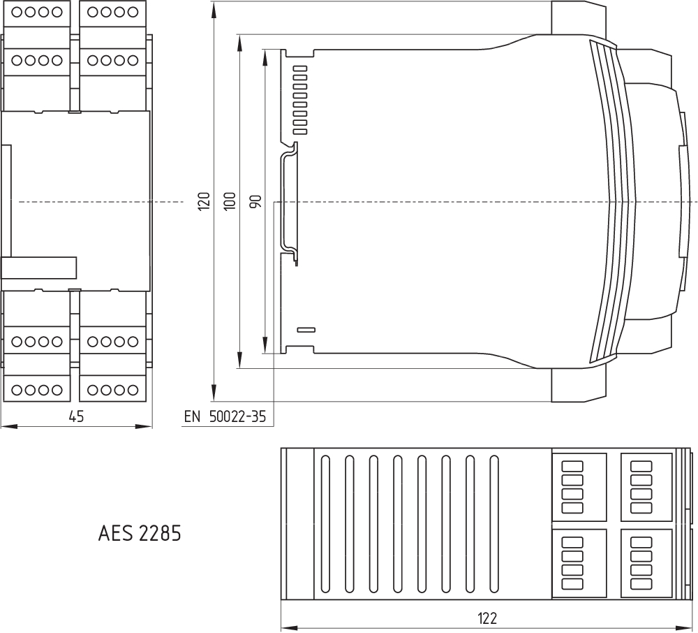
Mechanical data - Dimensions
| Width |
45 mm |
| Height |
100 mm |
| Depth |
121 mm |
Ambient conditions
| Degree of protection of the enclosure |
IP40 |
| Degree of protection of the mounting space |
IP54 |
| Degree of protection of clips or terminals |
IP20 |
| Ambient temperature |
-25 ... +45 °C |
| Storage and transport temperature |
-40 ... +85 °C |
| Resistance to vibrations |
10 ... 55 Hz, Amplitude 0.35 mm |
| Restistance to shock |
10 g / 11 ms |
Ambient conditions - Insulation values
| Rated impulse withstand voltage Uimp |
4 kV |
| Overvoltage category |
III |
| Degree of pollution |
2 |
Electrical data
| Frequency range |
50 Hz 60 Hz |
| Operating voltage |
24 VAC -15 % / +10 % |
| Ripple voltage |
10 % |
| Thermal test current |
6 A |
| Rated operating voltage |
24 VAC |
| Rated operating voltage |
24 VDC |
| Rated AC voltage for controls, 50 Hz, minimum |
20.4 VAC |
| Rated control voltage at AC 50 Hz, maximum |
26.4 VAC |
| Rated AC voltage for controls, 60 Hz, minimum |
20.4 VAC |
| Rated control voltage at AC 60 Hz, maximum |
26.4 VAC |
| Rated AC voltage for controls at DC minimum |
20.4 VDC |
| Rated control voltage at DC, maximum |
28.8 VDC |
| Electrical power consumption |
3.6 W |
| Electrical power consumption |
6.6 VA |
| Contact resistance, maximum |
0.1 Ω |
| Note (Contact resistance) |
in new state |
| Drop-out delay in case of power failure, typically |
80 ms |
| Drop-out delay in case of emergency, typically |
20 ms |
| Pull-in delay at automatic start, maximum, typically |
100 ms |
| Pull-in delay at RESET, typically |
20 ms |
| Material of the contacts, electrical |
AgCdO, self-cleaning, positive drive |
Electrical data - Safe relay outputs
| Voltage, Utilisation category AC-15 |
230 VAC |
| Current, Utilisation category AC-15 |
6 A |
| Voltage, Utilisation category DC-13 |
24 VDC |
| Current, Utilisation category DC-13 |
6 A |
| Switching capacity, minimum |
10 VDC |
| Switching capacity, minimum |
10 mA |
| Switching capacity, maximum |
250 VAC |
| Switching capacity, maximum |
8 A |
Electrical data - Digital inputs
| Conduction resistance, maximum |
40 Ω |
Electrical data - Digital Output
| Voltage, Utilisation category DC-12 |
24 VDC |
| Current, Utilisation category DC-12 |
0.1 A |
Electrical data - Relay outputs (auxiliary contacts)
| Switching capacity, maximum |
24 VDC |
| Switching capacity, maximum |
2 A |
Electrical data - Electromagnetic compatibility (EMC)
| EMC rating |
EMC-Directive |
Status indication
| Indicated operating states |
Position relay K2 Position relay K1 Internal operating voltage Ui |
Other data
| Note (applications) |
Safety sensor Guard system |
Note
| Note (General) |
Inductive loads (e.g. contactors, relays, etc.) are to be suppressed by means of a suitable circuit. |
Wiring example
| Note (Wiring diagram) |
The wiring diagram is shown with guard doors closed and in de-energised condition. The feedback circuit monitors the position of the contactors K3 and K4. Automatic start: The automatic start is programmed by connecting the feedback circuit to the terminals X1/X3. If the feedback circuit is not required, establish a bridge. To secure 6 guard doors up to PL d and Category 3 Monitoring 6 guard door(s), each with a magnetic safety sensor of the BNS range Start button (S) with edge detection |
Language filter
Datasheet
Operating instructions and Declaration of conformity
BG-test certificate
Wiring example (electr. wiring)
Force-travel diagram
SISTEMA-VDMA library
Download the latest version of Adobe Reader
Product picture (catalogue individual photo)
Dimensional drawing basic component
Symbol (technical standard)

Wiring example


103009970 SRB-E-201LC
- Plug-in screw terminals with coding
- STOP 0 Function
- 1 oder 2-channel control
- Start button / Auto-start
- 2 Safety outputs 2 A
- 1 Signalling output

103007672 SRB-E-301ST
- Plug-in screw terminals with coding
- STOP 0 Function
- 1 oder 2-channel control
- Start button / Auto-start
- 1 Auxiliary contact
- 3 safety contacts
| EU-Konformitätserklärung |  |
| Original | K.A. Schmersal GmbH & Co. KG Möddinghofe 30 42279 Wuppertal Germany Internet: www.schmersal.com |
| Erklärung: | Hiermit erklären wir, dass die nachfolgend aufgeführten Bauteile aufgrund der Konzipierung und Bauart den Anforderungen der unten angeführten Europäischen Richtlinien entsprechen. |
| Bezeichnung des Bauteils: | AES2285 |
| Beschreibung des Bauteils: | Relais-Sicherheitskombination für NOT-HALT-Schaltungen, Schutztürüberwachungen und Sicherheitsmagnetschalter |
| Einschlägige Richtlinien: | Maschinenrichtlinie | 2006/42/EG |
| EMV-Richtlinie | 2014/30/EU | |
| RoHS-Richtlinie | 2011/65/EU |
| Angewandte Normen: | EN 60947-5-1:2017 EN ISO 13849-1:2015 EN ISO 13849-2:2012 |
| Benannte Stelle für die Zertifizierung des QS-Systems nach Anhang X, 2006/42/EG: | TÜV Rheinland Industrie Service GmbH Am Grauen Stein, 51105 Köln Kenn-Nr.: 0035 |
| Bevollmächtigter für die Zusammenstellung der technischen Unterlagen: | Oliver Wacker Möddinghofe 30 42279 Wuppertal |
| Ort und Datum der Ausstellung: | Wuppertal, 25. Februar 2021 |
 |
| Rechtsverbindliche Unterschrift Philip Schmersal Geschäftsführer |
K.A. Schmersal GmbH & Co. KG, Möddinghofe 30, 42279 Wuppertal
The details and data referred to have been carefully checked. Images may diverge from original. Further technical data can be found in the manual. Technical amendments and errors possible.
Generated on: 20/04/2024, 01:50