BN 65-01Z/V
BN 65-01Z/V
Downloads
- With pre-wired cable
- Actuation from front
- with bias magnet
- Non-contact principle
- Long life
- Actuating surface and direction of actuation marked by switch symbol
- Construction form Ø 13 mm
- Thermoplastic enclosure
- Actuating distance up to 60 mm depending on actuating magnet and version
- with central mounting
Ordering data
| Product type description |
BN 65-01Z/V |
| Article number (order number) |
101055831 |
| EAN (European Article Number) |
4030661009872 |
| eCl@ss number, version 12.0 |
27-27-43-02 |
| eCl@ss number, version 11.0 |
27-27-01-05 |
| eCl@ss number, version 9.0 |
27-27-01-05 |
| ETIM number, version 7.0 |
EC002544 |
| ETIM number, version 6.0 |
EC002544 |
Approvals - Standards
| Certificates |
cULus |
General data
| Working principle |
Magnetic drive |
| Housing construction form |
Cylinder smooth |
| Housing material |
Glass-fibre, reinforced thermoplastic |
| Gross weight |
65 g |
General data - Features
| Suitable for elevators |
Yes |
| bias magnet |
Yes |
| Number of normally closed (NC) |
1 |
Mechanical data
| Actuating panels |
front side |
| Actuating element |
Magnet |
| Mechanical life, minimum |
1,000,000,000 Operations |
| Actuating speed, maximum |
18 m/s |
| Mounting |
central with threated flange |
| Tightening torque of nuts, maximum |
3 Nm |
Mechanical data - Switching distances according EN IEC 60947-5-3
| Switching distance Sn |
5 mm … 55 mm BP 10S = 5 mm 2 x BP 10S = 10 mm BP 15S = 6 mm BP 34S = 20 mm BP 20S = 15 mm BP 31S = 15 mm BP 11S = 5 mm 2 x BP 11S = 15 mm BP 12S = 10 mm 2 x BP 12S = 25 mm BP 21S = 30 mm 2 x BP 21S = 20 ... 55 mm BP 22S = 25 mm 2 x BP 22S = 15 ... 55 mm BE 20 S = 6 mm |
| Note (Switching distance Sn) |
Actuating distance up to 55 mm depending on actuating magnet and version. The specified switching distances are applicable for the actuation of individually mounted components without ferromagnetic influence. A change of the distance, either positive or negative, is possible due to ferromagnetic influences. The mutual interference between multiple actuating magnets must be observed. |
| Repeat accuracy R |
0.3 mm |
Mechanical data - Connection technique
| Length of cable |
1 m |
| Termination |
Cable |
| Wire cross-section |
0.75 mm2 |
| Wire cross-section |
18 AWG |
| Material of the Cable mantle |
H03VV-F |
Mechanical data - Dimensions
| Diameter of sensor |
13 mm |
| width across flats |
22 BK |
| Length of sensor |
103 mm |
Ambient conditions
| Degree of protection |
IP67 |
| Ambient temperature |
-25 ... +75 °C |
| Resistance to vibrations |
10 … 55 Hz, amplitude 1 mm |
| Restistance to shock |
30 g, on sine wave oscillation |
| Resistant to vibration |
30 g, on sine wave oscillation |
Electrical data
| Switching voltage, maximum |
250 VAC |
| Switching current, maximum |
3 A |
| Switching capacity, maximum |
120 W |
| Switching capacity, maximum |
120 VA |
| Switching element |
Opener (NC) |
| Bounce duration, minimum |
0.3 ms |
| Bounce duration, maximum |
0.6 ms |
| Switching frequency, maximum |
300 Hz |
| Maximum switching frequency |
1,080,000 /h |
Electrical data - Digital Output
| Design of control elements |
Reed contacts |
Scope of delivery
| Scope of delivery |
Actuator must be ordered separately. |
Accessory
| Recommendation (actuator) |
BP 10 S 2x BP 10 S BP 15 S BP 34 S BP 20 S BP 31 S BP 11 S 2x BP 11 S BP 12 S 2x BP 12S BP 21 S 2x BP 21 S BP 22 S 2x BP 22 S BE 20 S |
| Recommendation (actuator, lift switchgear) |
BP 10 2 x BP 10 BP 15 BP 34 |
Note
| Note (General) |
The switch is to be mounted on iron with a non-magnetic layer of at least 20 mm. |
Language filter
Datasheet
EC Declaration of conformity
UL Certificate
Info
Download the latest version of Adobe Reader
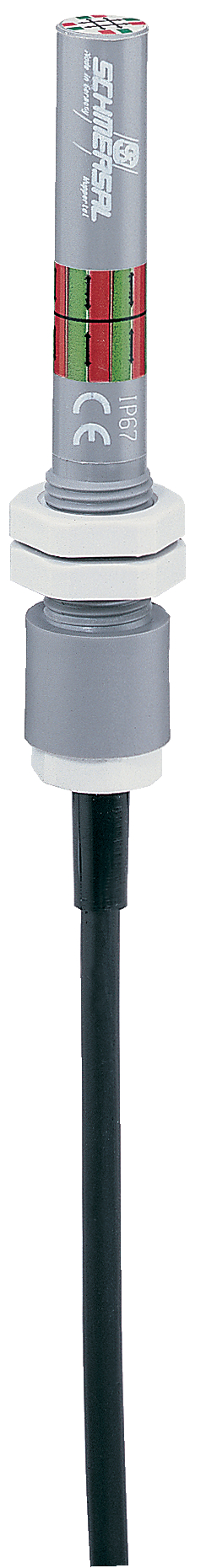
Product picture (catalogue individual photo)
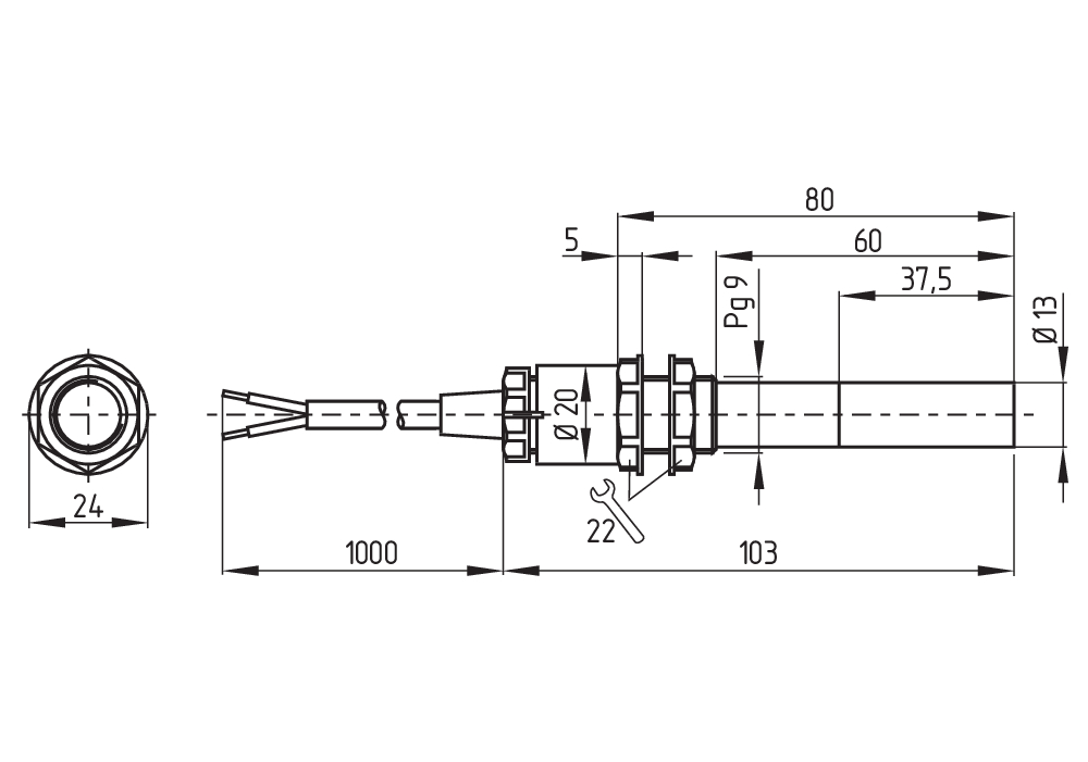
Dimensional drawing basic component
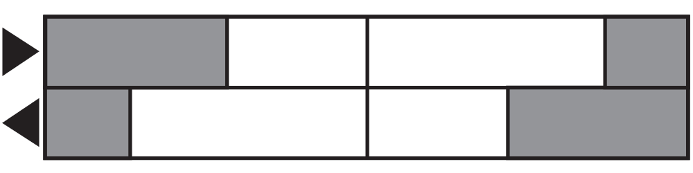
Switch travel diagram
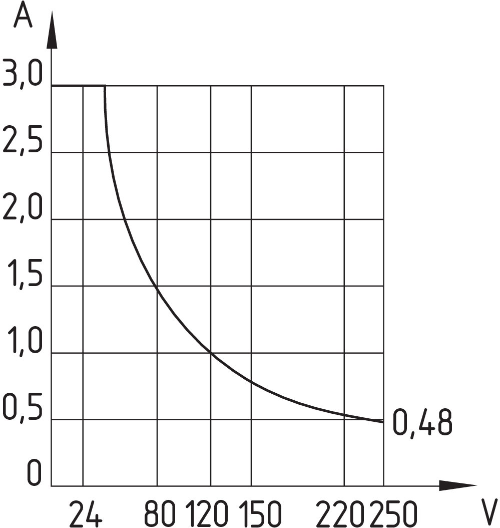
Diagram

Characteristic curve
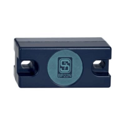
101057432 BP 22 N(S)
- -metal housing
- S-pole marked red
- N-pole marked green
- Suitable for mounting on ferrous material
- Can be used as N or S magnet
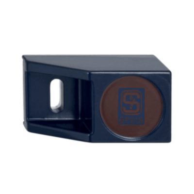
101057534 BP 21 S
- -metal housing
- S-pole marked red
- Suitable for mounting on ferrous material
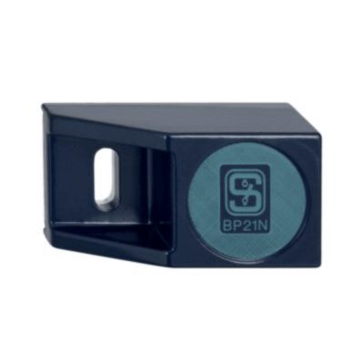
101057536 BP 21 N
- -metal housing
- N-pole marked green
- Suitable for mounting on ferrous material
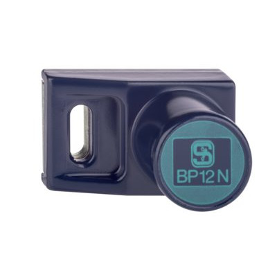
101059917 BP 12 N
- -metal housing
- N-pole marked green
- Suitable for mounting on ferrous material
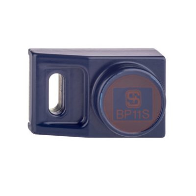
101057533 BP 11 S
- -metal housing
- S-pole marked red
- Suitable for mounting on ferrous material

101059923 BP 11 N
- -metal housing
- N-pole marked green
- Suitable for mounting on ferrous material
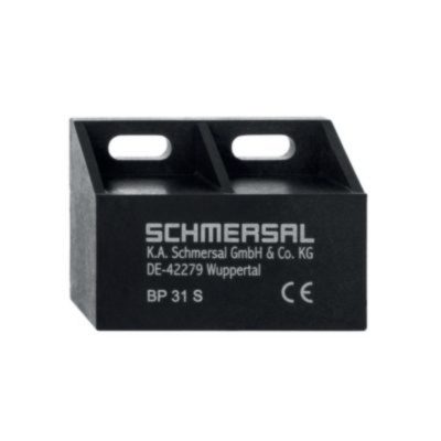
101057521 BP 31 S
- thermoplastic enclosure
- S-pole marked red
- Suitable for mounting on ferrous material with a distance of 20 mm
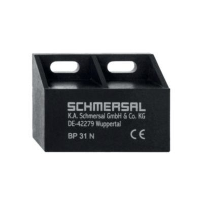
101057520 BP 31 N
- thermoplastic enclosure
- N-pole marked green
- Suitable for mounting on ferrous material with a distance of 20 mm

101057530 BP 31
- thermoplastic enclosure
- S-pole marked red
- N-pole marked green
- Suitable for mounting on ferrous material with a distance of 20 mm
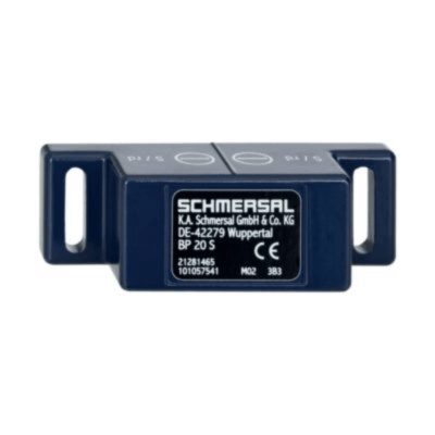
101057541 BP 20 S
- -metal housing
- S-pole marked red
- Suitable for mounting on ferrous material with a distance of 20 mm
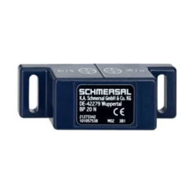
101057538 BP 20 N
- -metal housing
- N-pole marked green
- Suitable for mounting on ferrous material with a distance of 20 mm
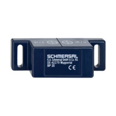
101057549 BP 20
- -metal housing
- S-pole marked red
- N-pole marked green
- Suitable for mounting on ferrous material with a distance of 20 mm
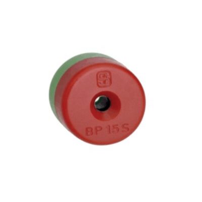
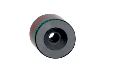
101060163 BP 15
- thermoplastic enclosure
- N-pole marked green
- S-pole marked red
- Suitable for mounting on ferrous material with a distance of 18 mm
101057531 BP 10
- Unenclosed
- Colour coding of poles by lables
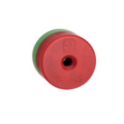
101057553 BP 34
- thermoplastic enclosure
- S-pole marked red
- N-pole marked green
- Suitable for mounting on ferrous material with a distance of 25 mm
K.A. Schmersal GmbH & Co. KG, Möddinghofe 30, 42279 Wuppertal
The details and data referred to have been carefully checked. Images may diverge from original. Further technical data can be found in the manual. Technical amendments and errors possible.
Generated on: 23/04/2024, 14:02