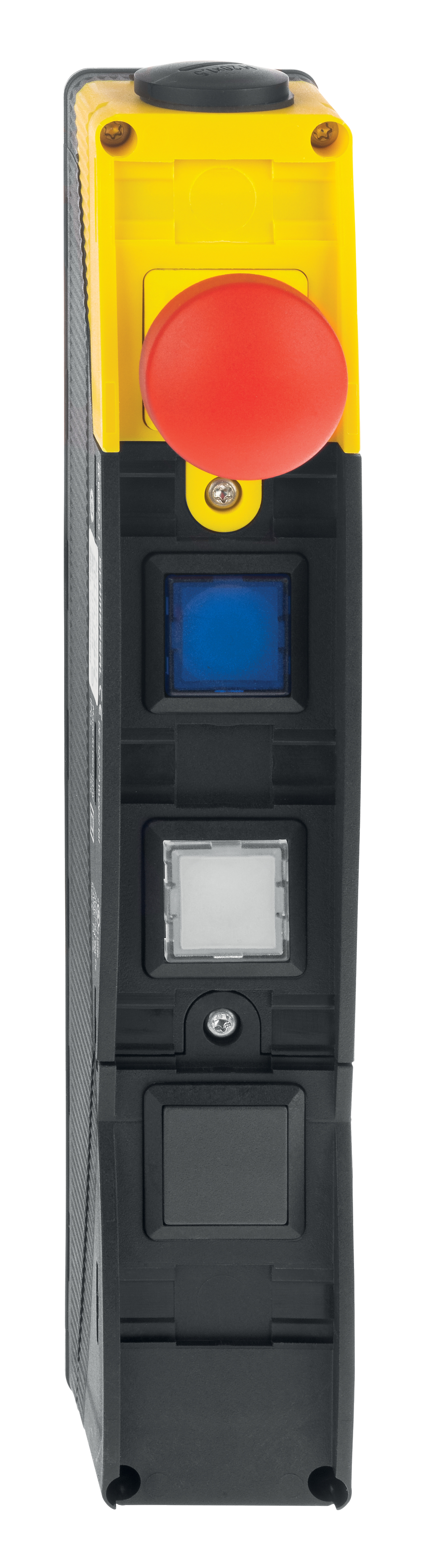
BDF200-NH-11-LTBU-LTWH-B
BDF200-NH-11-LTBU-LTWH-B
| Product type description: BDF 200-(1)-(2)-(3)-(4)-(5)-(6) |
| (1) | |
| NH | Emergency stop pushbutton without protective collar |
| NHK | Emergency stop with protective collar |
| LT.. | Selection (Color Illuminated pushbutton) |
| LM.. | Indicator light (selection colour) |
| DT.. | Push button (Selection Color) |
| PT.. | Mushroom push button |
| (2) | |
| 20 | with EMERGENCY-STOP: 2 NO position 2-4 > without EMERGENCY STOP: 2 NO position 1-4 |
| 11 | with EMERGENCY-STOP: 1 NO/1 NC position 2-4 > without EMERGENCY STOP: 1 NO/1 NC position 1-4 |
| 10 | with EMERGENCY-STOP: 1 NO position 2-4 > without EMERGENCY STOP: 1 NO position 1-4 |
| (3) | |
| WS 2/3 | Selector switch, 2/3 switch position |
| WT 2/3 | Selector switch, 2/3 switch positions |
| SW 20 | Key switch/button, 2 switch positions |
| LT.. | Illuminated control push button (selection colour) |
| LM.. | Indicator light (selection colour) |
| DT.. | Push button (Selection Color) |
| PT.. | Mushroom push button |
| (4) | |
| WS 2/3 | Selector switch, 2/3 switch position |
| WT 2/3 | Selector switch, 2/3 switch positions |
| SW 20 | Key switch/button, 2 switch positions |
| LT.. | Illuminated control push button (selection colour) |
| LM.. | Indicator light (selection colour) |
| DT.. | Push button (Selection Color) |
| PT.. | Mushroom push button |
| (5) | |
| LT.. | Illuminated control push button (selection colour) |
| LM.. | Indicator light (selection colour) |
| DT.. | Push button (Selection Color) |
| PT.. | Mushroom push button |
| (6) | |
| without | without indicator lamp |
| G24 | with indicator lamp, red (only for -10) |
| (7) | |
| without | Included in standard version |
| 2875 | Freely installable button caps |
- slender shock-proof thermoplastic enclosure
- to be installed at an ergonomic favourable position
- to be fitted to commercial-off-the-shelf aluminium profiles
- Thermoplastic enclosure
- slender shock-proof enclosure
- large range of Illuminated pushbuttons, Selector switches, LED indicator lights, Key-operated selector switches and Emergency-Stop buttons
- Emergency stop, on/off and reset functions available
- The position of the pushbuttons on the control panel can be freely selected.
- Field labelling with separate plastic cover
- Freely installable button caps for an optimal adaptation to the plants
Ordering data
| Product type description |
BDF200-NH-11-LTBU-LTWH-B |
| Article number (order number) |
101216487 |
| EAN (European Article Number) |
4030661576046 |
| eCl@ss number, version 12.0 |
27-37-12-16 |
| eCl@ss number, version 11.0 |
27-37-12-16 |
| eCl@ss number, version 9.0 |
27-37-12-16 |
| ETIM number, version 7.0 |
EC000225 |
| ETIM number, version 6.0 |
EC000225 |
| Note (Ordering data) |
Notice: see ordering code |
Approvals - Standards
| Certificates |
cULus |
General data
| Standards |
EN ISO 13850 EN IEC 60947-5-1 EN IEC 60947-5-5 EN IEC 60947-1 |
|
| Climatic stress |
DIN EN 60068 |
|
| Versions |
Assembly housing |
|
| Housing material |
Plastic, glass-fibre reinforced thermoplastic, self-extinguishing |
|
| Positions used, position 1 |
Emergency stop pushbutton |
|
| Positions used, position 2 |
|
|
| Positions used, position 3 |
Illuminated pushbutton, white |
|
| Positions used, position 4 |
|
|
| Gross weight |
280 g |
General data - Features
| Emergency-Stop button |
Yes |
| Safety functions |
Yes |
| Removable Terminals |
Yes |
| Number of cable wires |
16 |
| Safety classification |
| Standards |
EN ISO 13849-1 |
| Mission time |
20 Year(s) |
Safety classification - Safety outputs
| B10D Normally-closed contact (NC) |
100,000 Operations |
Mechanical data
| Position of the cable gland |
bottom |
| Mechanical life, Emergency-Stop button |
100,000 Operations |
| Mechanical life, Command devices |
1,000,000 Operations |
| Actuating stroke |
3 mm |
| Actuating force, maximum |
8 N |
| Note (Actuating force) |
each contact |
| Contact force, typically |
1 N |
| Mounting |
interior mounting holes |
| Type of the fixing screws |
2x M5 |
| Tightening torque of the fastening screws for the housing cover, minimum |
0.7 Nm |
| Tightening torque of the fastening screws for the housing cover, maximum |
0.8 Nm |
| Tightening torque of the cable gland, maximum |
4 Nm |
| Note |
Miaximum tightening cable gland cap nut 3 Nm |
Mechanical data - Connection technique
| Cable entry |
M20 cable gland |
| Cable cross-section of the cable glands, minimum |
6 mm |
| Cable cross-section of the cable glands, maximum |
13 mm |
| Wire cross-section |
0.5 mm2 |
| Terminal (mechanical) |
Removable screw terminals |
Mechanical data - Dimensions
| Width |
40 mm |
| Height |
69 mm |
| Depth |
249 mm |
Ambient conditions
| Degree of protection |
IP65 |
| Ambient temperature |
-25 ... +65 °C |
| Resistance to vibrations |
10 … 100 Hz, with 20 g |
| Restistance to shock |
100 g / 6 ms |
Ambient conditions - Insulation values
| Rated insulation voltage Ui |
250 VAC |
| Rated impulse withstand voltage Uimp |
2.5 kV |
| Overvoltage category |
III |
| Degree of pollution |
3 |
Electrical data
| Thermal test current |
2.5 A |
| LED current consumption (operating elements) |
16 mA |
| Rated operating voltage |
24 VDC |
| Utilisation category AC-15 |
24 VAC |
| Utilisation category AC-15 |
2 A |
| Utilisation category DC-13 |
24 VDC |
| Utilisation category DC-13 |
1 A |
| External wire and device fuse rating |
2.5A T |
| Suitable for low-voltages |
≥ 5 V / ≥ 1 mA |
| Switching principle |
Slow action cross-point-system |
| Maximum switching frequency |
1,200 /h |
| Material of the contacts, electrical |
Ag-Ni 10, gold-plated |
Status indication
| Colour of the indicator lamp |
without (Blanking plug, black) |
Other data
| Note (applications) |
Suitable for 40 mm profiles |
Language filter
Datasheet
Operating instructions and Declaration of conformity
UL Certificate
Brochure
SISTEMA-VDMA library
Download the latest version of Adobe Reader
Product picture (catalogue individual photo)
K.A. Schmersal GmbH & Co. KG, Möddinghofe 30, 42279 Wuppertal
The details and data referred to have been carefully checked. Images may diverge from original. Further technical data can be found in the manual. Technical amendments and errors possible.
Generated on: 23/04/2024, 22:51