EX-AZ 335-12ZRK-3D
EX-AZ 335-12ZRK-3D
| Product type description: EX-AZ 335-(1)-Z(2)K-(3)-3D |
| (1) | |
| 03 | 3 NC contact |
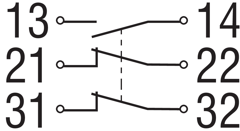
| 12 | 1 NO contact/2 NC contacts |
| (2) | |
| without | Latching force 5 N |
| R | Latching force 30 N |
| UE | Slow action with overlapping contacts |
| (3) | |
| 1637 | Gold-plated contacts |
- Metal enclosure
- 3 Contacts
- 40,5 mm x 114 mm x 38 mm
- Long life
- Can be mounted on a flat surface
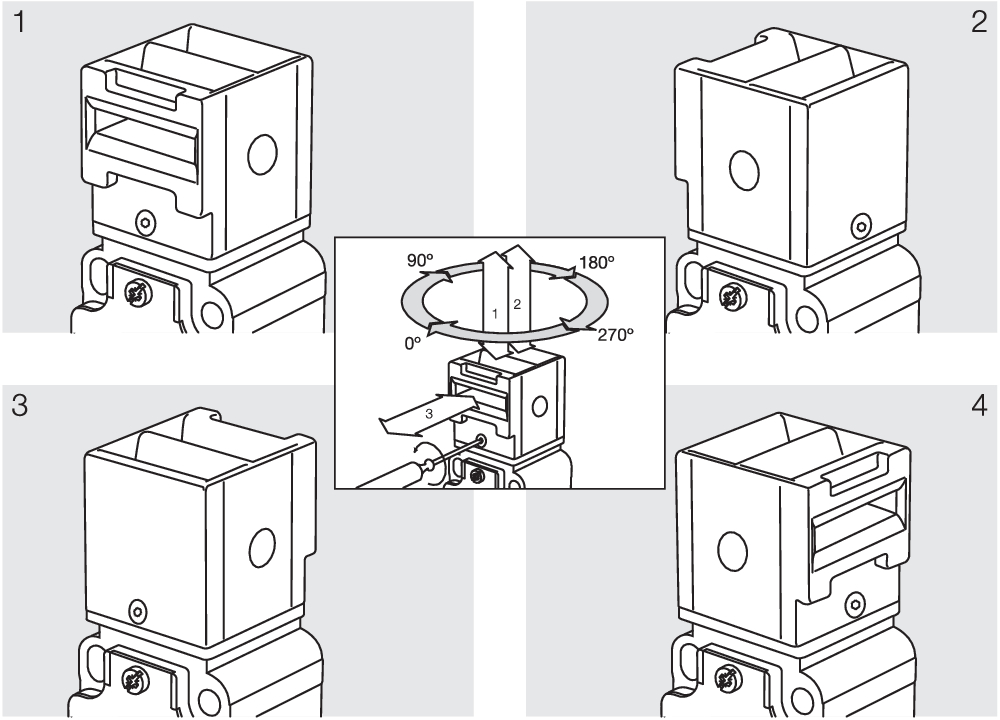
- Actuator heads can be repositioned in steps 4 x 90°
- Mounting details to EN 50041
- High level of contact reliability with low voltages and currents
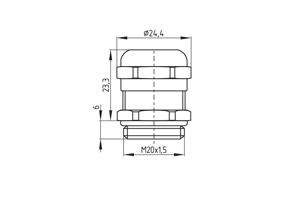
- 1 Cable entry M 20 x 1.5
- Slotted holes for adjustment, circular holes for location
- Transverse and longitudinal slotted holes
Ordering data
| Note (Delivery capacity) |
Not available! |
| Product type description |
EX-AZ 335-12ZRK-3D |
| Article number (order number) |
101189286 |
| eCl@ss number, version 12.0 |
27-27-26-02 |
| eCl@ss number, version 11.0 |
27-27-26-02 |
| eCl@ss number, version 9.0 |
27-27-26-02 |
| ETIM number, version 7.0 |
EC002592 |
| ETIM number, version 6.0 |
EC002592 |
Explosion protection
| Explosion protection zones |
22 |
| Explosion protection category |
3D |
| Explosion protection designation |
Ex tD A22 IP67 T90°C X |
General data
| Standards |
BG-GS-ET-15 EN IEC 60947-5-1 |
| Housing material |
Light alloy die-casting |
| Housing coating material |
painted |
| Gross weight |
300 g |
General data - Features
| Increased latching force |
Yes |
| Number of auxiliary contacts |
1 |
| Number of safety contacts |
2 |
| Safety classification |
| Standards |
EN ISO 13849-1 |
| Mission time |
20 Year(s) |
Safety classification - Safety outputs
| B10D Normally-closed contact (NC) |
2,000,000 Operations |
| B10D Normally open contact (NO) |
1,000,000 Operations |
Mechanical data
| Mechanical life, minimum |
10,000,000 Operations |
| Latching force |
30 N |
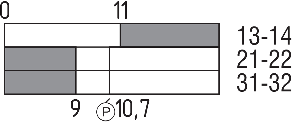
| Positive break travel |
10.7 mm |
| Positive break force, minimum |
5 N |
| Actuating speed, maximum |
1 m/s |
Mechanical data - Connection technique
| Termination |
Screw terminals M20 x 1.5 |
| Cable cross-section of the cable glands, minimum |
6 mm |
| Cable cross-section of the cable glands, maximum |
12 mm |
| Cable section, minimum |
0.75 mm² |
| Cable section, maximum |
2.5 mm² |
| Note |
All indications including the conductor ferrules. |
Mechanical data - Dimensions
| Length of sensor |
38 mm |
| Width of sensor |
40.5 mm |
| Height of sensor |
114 mm |
Ambient conditions
| Degree of protection |
IP67 |
| Ambient temperature |
-20 ... +60 °C |
Ambient conditions - Insulation values
| Rated insulation voltage Ui |
250 VAC |
| Rated impulse withstand voltage Uimp |
4 kV |
Electrical data
| Thermal test current |
10 A |
| Utilisation category AC-15 |
230 VAC |
| Utilisation category AC-15 |
4 A |
| Utilisation category DC-13 |
24 VDC |
| Utilisation category DC-13 |
4 A |
| Switching element |
NO contact, NC contact |
| Switching principle |
Slow action |
| Material of the contacts, electrical |
Silver |
Scope of delivery
| Scope of delivery |
Actuator must be ordered separately. Ex-certified screwed cable gland |
Note
| Note (General) |
By turning the head in 90° steps, 8 actuating planes are possible. A Torx T10 screwdriver is required for this purpose. Even when the screw is removed, the head is self-retaining. The switch can still not be tampered. |
Language filter
Datasheet
Operating instructions and Declaration of conformity
SISTEMA-VDMA library
Download the latest version of Adobe Reader
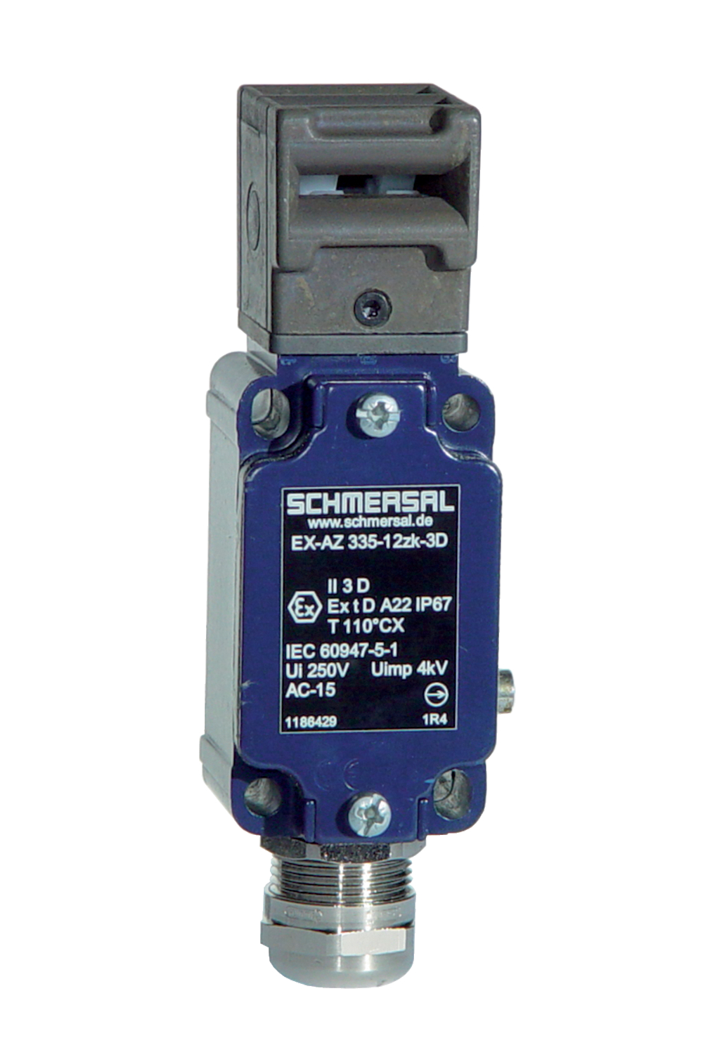
Product picture (catalogue individual photo)
Dimensional drawing basic component
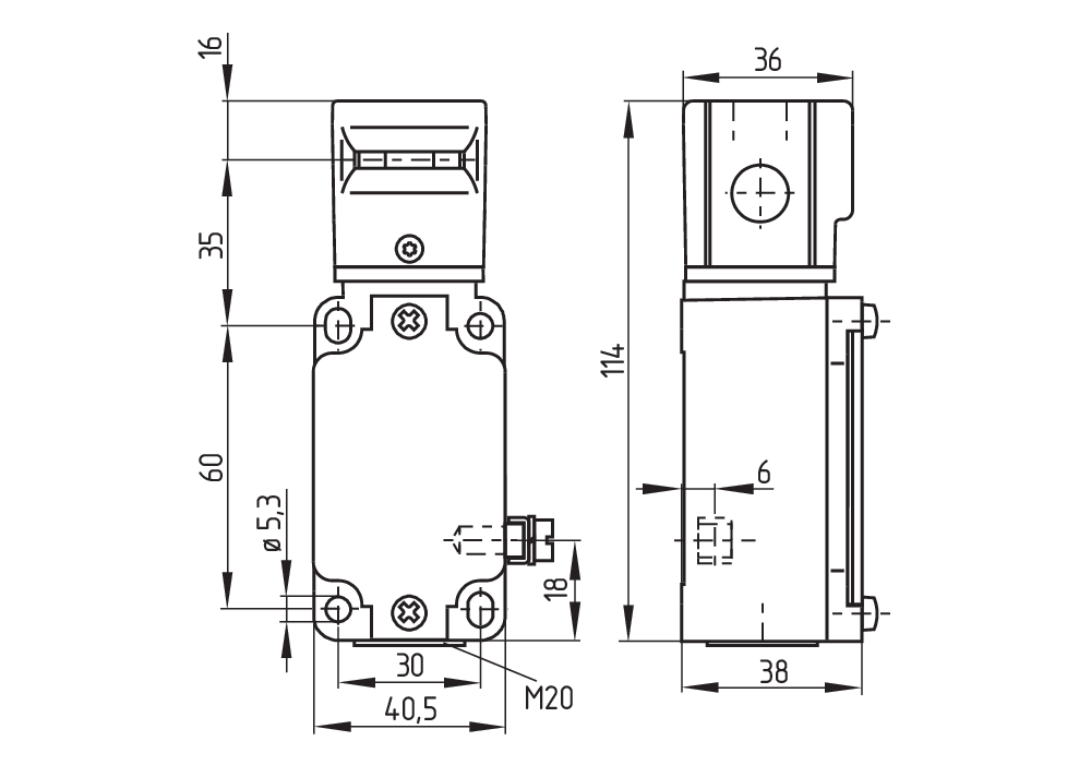
Dimensional drawing basic component
Switch travel diagram
Diagram
Operating principle
K.A. Schmersal GmbH & Co. KG, Möddinghofe 30, 42279 Wuppertal
The details and data referred to have been carefully checked. Images may diverge from original. Further technical data can be found in the manual. Technical amendments and errors possible.
Generated on: 18/04/2024, 14:01