AZR31S1-2SEC./230VAC
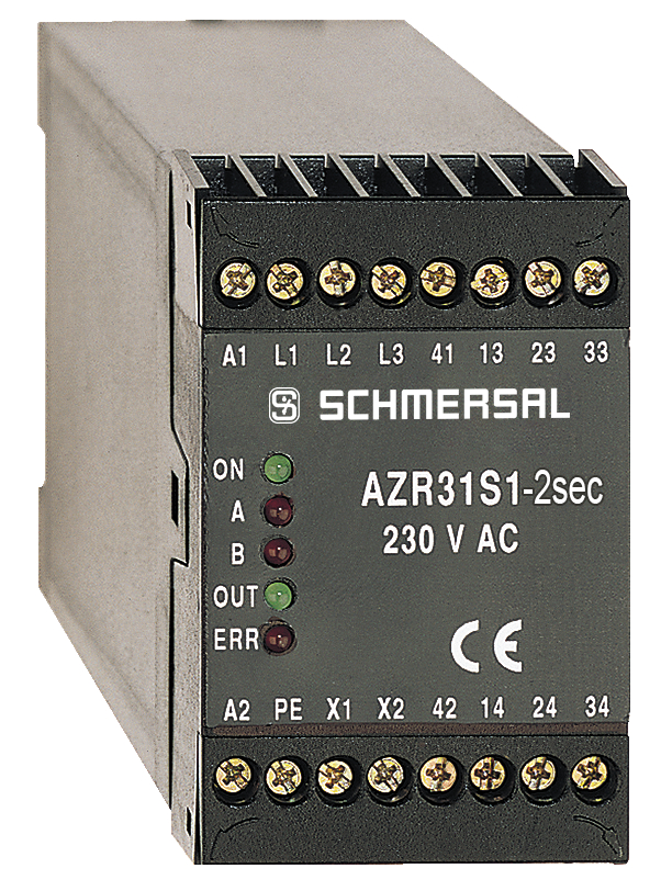
AZR31S1-2SEC./230VAC
- Fail-safe standstill monitors
- Sensor-free detection of standstill by monitoring e.m.f.
- Direct connection to three-phase motors
- Suitable for connection to a frequency converter with the following interface date: rotary hysteresis 0 ... 1000 Hz; switching frequency of the end level up to 16 kHz; engine voltage range 0 ... 400 V
- This fail-safe standstill monitor has the particular advantage that no adjustment for a required-value is needed during comissioning.
- 3 safety contacts, STOP 0
- 1 Signalling output
Ordering data
| Note (Delivery capacity) |
Not available! |
| Product type description |
AZR31S1-2SEC./230VAC |
| Article number (order number) |
101179105 |
| EAN (European Article Number) |
4030661446554 |
| eCl@ss number, version 12.0 |
27-37-18-19 |
| eCl@ss number, version 11.0 |
27-37-18-19 |
| eCl@ss number, version 9.0 |
27-37-18-19 |
| ETIM number, version 7.0 |
EC001449 |
| ETIM number, version 6.0 |
EC001449 |
General data
| Standards |
EN IEC 62061 EN ISO 13849-1 EN IEC 60947-5-1 EN IEC 60947-5-3 EN IEC 60947-5-5 EN IEC 61508 EN IEC 60204-1 EN IEC 60947-1 |
| Climatic stress |
EN 60068-2-78 |
| Housing material |
Glass-fibre, reinforced thermoplastic |
| Gross weight |
400 g |
General data - Features
| Wire breakage detection |
Yes |
| Cross-circuit detection |
Yes |
| Feedback circuit |
Yes |
| Automatic reset function |
Yes |
| Earth connection detection |
Yes |
| Integral system diagnostics, status |
Yes |
| Number of auxiliary contacts |
1 |
| Number of LEDs |
5 |
| Number of safety contacts |
3 |
| Safety classification |
| Standards |
EN IEC 60947-5-1 EN IEC 61508 |
| PFH value |
2.00 x 10⁻⁸ /h |
| Mission time |
20 Year(s) |
| Common Cause Failure (CCF), minimum |
65 |
| Stop-Category |
0 |
| Safety classification - Relay outputs |
| Performance Level, stop 0, up to |
e |
| Category, Stop 0 |
4 |
| Diagnostic Coverage (DC) Level, Stop 0 |
≥ 99 % |
| Safety Integrity Level (SIL), Stop 0, suitable for applications in |
3 |
Mechanical data
| Mechanical life, minimum |
10,000,000 Operations |
| Mounting |
Snaps onto standard DIN rail to EN 60715 |
Mechanical data - Connection technique
| Terminal designations |
IEC/EN 60947-1 |
| Termination |
rigid or flexible Screw terminals M20 x 1.5 |
| Cable section, minimum |
0.25 mm² |
| Cable section, maximum |
2.5 mm² |
| Tightening torque of Clips |
0.6 Nm |
Mechanical data - Dimensions
| Width |
45 mm |
| Height |
73.2 mm |
| Depth |
121 mm |
Ambient conditions
| Degree of protection of the enclosure |
IP40 |
| Degree of protection of the mounting space |
IP54 |
| Degree of protection of clips or terminals |
IP20 |
| Ambient temperature |
-25 ... +45 °C |
| Storage and transport temperature |
-40 ... +85 °C |
| Resistance to vibrations |
10 ... 55 Hz, Amplitude 0.35 mm |
| Restistance to shock |
30 g / 11 ms |
Ambient conditions - Insulation values
| Rated impulse withstand voltage Uimp |
4 kV |
| Overvoltage category |
III |
| Degree of pollution |
2 |
Electrical data
| Frequency range |
50 Hz 60 Hz |
| Operating voltage |
230 VAC -15 % / +10 % |
| Rated operating voltage |
230 VAC |
| Rated AC voltage for controls, 50 Hz, minimum |
195.5 VAC |
| Rated control voltage at AC 50 Hz, maximum |
253 VAC |
| Rated AC voltage for controls, 60 Hz, minimum |
195.5 VAC |
| Rated control voltage at AC 60 Hz, maximum |
253 VAC |
| Electrical power consumption, maximum |
4 VA |
| Contact resistance, maximum |
0.1 Ω |
| Note (Contact resistance) |
in new state |
| Cable length (Master/Slave), maximum |
10 m |
| Drop-out delay in case of power failure, typically |
80 ms |
| Drop-out delay in case of emergency, typically |
20 ms |
| Drop-out delay in case of "emergency stop", maximum |
15 ms |
| Pull-in delay at automatic start (after detecting standstill), approx. |
2,000 ms |
| Pull-in delay at RESET, typically |
20 ms |
| Material of the contacts, electrical |
AgSn0. self-cleaning, positive drive |
Electrical data - Safe relay outputs
| Voltage, Utilisation category AC-15 |
230 VAC |
| Current, Utilisation category AC-15 |
6 A |
| Voltage, Utilisation category DC-13 |
24 VDC |
| Current, Utilisation category DC-13 |
6 A |
| Switching capacity, minimum |
10 VDC |
| Switching capacity, minimum |
10 mA |
| Switching capacity, maximum |
250 VAC |
| Switching capacity, maximum |
8 A |
Electrical data - Digital inputs
| Conduction resistance, maximum |
40 Ω |
Electrical data - Digital Output
| Voltage, Utilisation category DC-12 |
24 VDC |
| Current, Utilisation category DC-12 |
0.1 A |
Electrical data - Relay outputs (auxiliary contacts)
| Switching capacity, maximum |
24 VDC |
| Switching capacity, maximum |
2 A |
Electrical data - Electromagnetic compatibility (EMC)
| EMC rating |
EMC-Directive |
Status indication
| Indicated operating states |
OUT, green: release ON, green: supply voltage UB ERR, red: error channel A + B |
Other data
| Note (applications) |
safe standstill monitoring |
Note
| Note (General) |
Inductive loads (e.g. contactors, relays, etc.) are to be suppressed by means of a suitable circuit. |
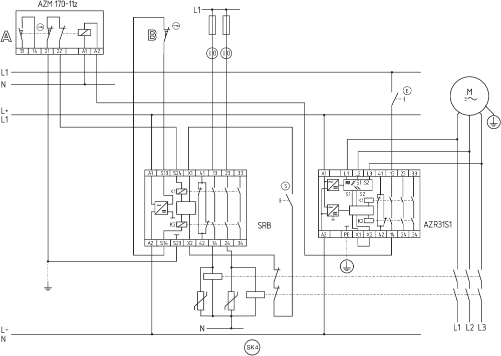
Wiring example
| Note (Wiring diagram) |
The wiring diagram is shown with guard doors closed and in de-energised condition. The sensor-free standstill monitor checks the e.m.f. of the three phase motor. The SRB range guard door monitor checks the position of the guard door. Monitoring the guard door using a solenoid interlock and a safety switch with separate actuator (A and B). Release takes place by means of the NO contact (E) only when the run-down movement has been terminated. After release has taken place, the guard door must be opened. To secure a guard door |
Language filter
Datasheet
Operating instructions and Declaration of conformity
Wiring example (electr. wiring)
SISTEMA-VDMA library
Download the latest version of Adobe Reader
Product picture (catalogue individual photo)
Symbol (technical standard)

Wiring example
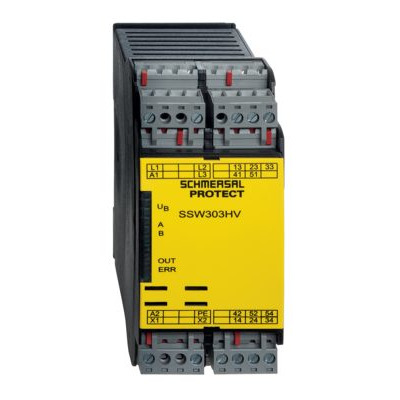
103037586 SSW303HV-2S
- Standstill detection time 2s
- Fail-safe standstill monitors
- 3 safety contacts
- 3 Signalling contacts
- Sensor-free detection of standstill by monitoring e.m.f.
- Direct connection to three-phase motors
- Motor voltage range 0 ... 690 V
| EU-Konformitätserklärung |  |
| Original | K.A. Schmersal GmbH & Co. KG Möddinghofe 30 42279 Wuppertal Germany Internet: www.schmersal.com |
| Erklärung: | Hiermit erklären wir, dass die nachfolgend aufgeführten Bauteile aufgrund der Konzipierung und Bauart den Anforderungen der unten angeführten Europäischen Richtlinien entsprechen. |
| Bezeichnung des Bauteils: | AZR31S1 |
| Typ: | siehe Typenschlüssel |
| Beschreibung des Bauteils: | Relais-Sicherheitskombination zur Überwachung des Motorstillstands |
| Einschlägige Richtlinien: | Maschinenrichtlinie | 2006/42/EG |
| EMV-Richtlinie | 2014/30/EU | |
| RoHS-Richtlinie | 2011/65/EU |
| Angewandte Normen: | EN 60947-5-1:2017 EN ISO 13849-1:2015 EN ISO 13849-2:2012 |
| Benannte Stelle für die Zertifizierung des QS-Systems nach Anhang X, 2006/42/EG: | TÜV Rheinland Industrie Service GmbH Am Grauen Stein, 51105 Köln Kenn-Nr.: 0035 |
| Bevollmächtigter für die Zusammenstellung der technischen Unterlagen: | Oliver Wacker Möddinghofe 30 42279 Wuppertal |
| Ort und Datum der Ausstellung: | Wuppertal, 4. Januar 2021 |
 |
| Rechtsverbindliche Unterschrift Philip Schmersal Geschäftsführer |
Schmersal, Inc., 115 E Stevens Ave, Suite 208, Valhalla, NY 10595
The details and data referred to have been carefully checked. Images may diverge from original. Further technical data can be found in the manual. Technical amendments and errors possible.
Generated on: 4/18/2024, 10:18 AM