SRB-E-302FWS-TS
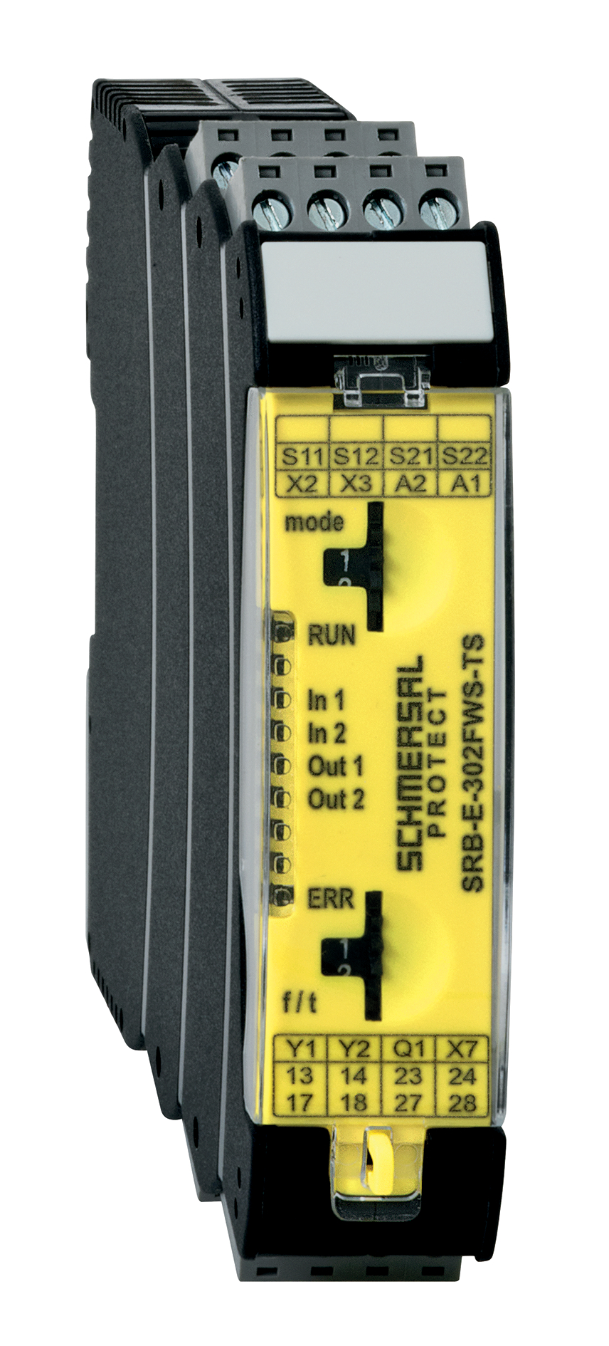
SRB-E-302FWS-TS
- 2 Safety contacts, 1 Safety Output
- Plug-in screw terminals with coding
- 1 Signalling output - status safety module
- 1 Signalling output - failure massage dynamic
- Detects standstill using 1 or 2 impulse sensors
- additional standstill signal, e.g. PLC as second input channel
- 2-channel time monitoring
Ordering data
| Product type description |
SRB-E-302FWS-TS |
| Article number (order number) |
103014754 |
| EAN (European Article Number) |
4030661511276 |
| eCl@ss number, version 12.0 |
27-37-18-19 |
| eCl@ss number, version 11.0 |
27-37-18-19 |
| eCl@ss number, version 9.0 |
27-37-18-19 |
| ETIM number, version 7.0 |
EC001449 |
| ETIM number, version 6.0 |
EC001449 |
Approvals - Standards
| Certificates |
TÜV cULus CCC |
General data
| Standards |
EN IEC 62061 EN ISO 13849-1 EN IEC 60947-5-1 EN IEC 60947-5-3 EN IEC 60947-5-5 EN IEC 61508 EN IEC 60204-1 EN IEC 60947-1 |
| Climatic stress |
EN 60068-2-78 |
| Housing material |
Glass-fibre reinforced thermoplastic, ventilated |
| Gross weight |
170 g |
General data - Features
| Electronic Fuse |
Yes |
| Wire breakage detection |
Yes |
| Cross-circuit detection |
Yes |
| Start input |
Yes |
| Feedback circuit |
Yes |
| Automatic reset function |
Yes |
| Reset edge detection |
Yes |
| Earth connection detection |
Yes |
| Integral system diagnostics, status |
Yes |
| Number of inputs for NC |
2 |
| Number of inputs for NO |
1 |
| Number of LEDs |
6 |
| Number of safety contacts |
2 |
| Number of fail-safe digital outputs |
1 |
| Number of signalling outputs |
2 |
| Safety classification |
| Standards |
EN ISO 13849-1 EN IEC 62061 EN IEC 61508 |
| Stop-Category |
0 |
| Safety classification - Relay outputs |
| Performance Level, up to |
e |
| Category |
4 |
| Diagnostic Coverage (DC) Level |
> 94 % |
| PFH value |
1.25 x 10⁻⁸ /h |
| PFD value |
5.30 x 10⁻⁵ |
| Safety Integrity Level (SIL), suitable for applications in |
3 |
| Mission time |
20 Year(s) |
| Common Cause Failure (CCF), minimum |
65 |
| Safety classification - Fail-safe digital outputs |
| Performance Level, up to |
e |
| Category |
4 |
| PFH value |
2.66 x 10⁻⁹ /h |
| PFD value |
2.42 x 10⁻⁵ |
| Safety Integrity Level (SIL), suitable for applications in |
3 |
| Mission time |
20 Year(s) |
Mechanical data
| Mechanical life, minimum |
10,000,000 Operations |
| Mounting |
Snaps onto standard DIN rail to EN 60715 |
Mechanical data - Connection technique
| Terminal designations |
IEC 60947-1 |
| Termination |
rigid or flexible Screw connection, plug-in |
| Cable section, minimum |
0.25 mm² |
| Cable section, maximum |
2.5 mm² |
| Tightening torque of Clips |
0.5 Nm |
Mechanical data - Dimensions
| Width |
22.5 mm |
| Height |
98 mm |
| Depth |
115 mm |
Ambient conditions
| Degree of protection of the enclosure |
IP40 |
| Degree of protection of the mounting space |
IP54 |
| Degree of protection of clips or terminals |
IP20 |
| Ambient temperature |
-25 ... +60 °C |
| Storage and transport temperature |
-40 ... +85 °C |
| Resistance to vibrations |
10 ... 55 Hz, Amplitude 0.35 mm |
| Restistance to shock |
30 g / 11 ms |
Ambient conditions - Insulation values
| Rated insulation voltage Ui |
250 V / 50 V |
| Rated impulse withstand voltage Uimp, relay output |
4 kV |
| Rated impulse withstand voltage Uimp, semiconductor output |
0.8 kV |
| Overvoltage category |
III |
| Degree of pollution |
2 |
Electrical data
| Operating voltage |
24 VDC -20 % / +20 % |
| Ripple voltage |
10 % |
| Rated operating voltage |
24 VDC |
| Operating current |
125 mA |
| Rated AC voltage for controls at DC minimum |
19.2 VDC |
| Rated control voltage at DC, maximum |
28.8 VDC |
| Electrical power consumption |
3 W |
| Contact resistance, maximum |
0.1 Ω |
| Note (Contact resistance) |
in new state |
| Drop-out delay in case of power failure, typically |
10 ms |
| Drop-out delay in case of emergency, typically |
10 ms |
| Pull-in delay at automatic start, maximum, typically |
150 ms |
| ON delay at automatic start |
Adjustable |
| Pull-in delay at RESET, typically |
150 ms |
| Switching frequency, maximum |
0.3 Hz |
| Material of the contacts, electrical |
Ag-Ni, self-cleaning, positive drive |
Electrical data - Safety digital outputs
| Voltage drop Ud, maximum |
0.5 V |
| Leakage current Ir, maximum |
1 mA |
| Voltage, Utilisation category DC-13 |
24 VDC |
| Current, Utilisation category DC-13 |
2 A |
Electrical data - Safe relay outputs
| Voltage, Utilisation category AC-15 |
230 VAC |
| Current, Utilisation category AC-15 |
4 A |
| Voltage, Utilisation category DC-13 |
24 VDC |
| Current, Utilisation category DC-13 |
4 A |
| Switching capacity, minimum |
10 VDC |
| Switching capacity, minimum |
10 mA |
| Switching capacity, maximum |
250 VAC |
| Switching capacity, maximum |
6 A |
Electrical data - Digital inputs
| Conduction resistance, maximum |
40 Ω |
Electrical data - Digital Output
| Voltage, Utilisation category DC-12 |
24 VDC |
| Current, Utilisation category DC-12 |
0.1 A |
Electrical data - Relay outputs (auxiliary contacts)
| Switching capacity, maximum |
24 VDC |
| Switching capacity, maximum |
1 A |
Electrical data - Electromagnetic compatibility (EMC)
| EMC rating |
EMC-Directive |
Status indication
| Indicated operating states |
Internal operating voltage Ui Baustein-Status Fault codes |
Other data
| Note (applications) |
safe standstill monitoring Fail-safe delay timer |
Language filter
Datasheet
Operating instructions and Declaration of conformity
BG-test certificate
CCC certification
UL Certificate
SISTEMA-VDMA library
Download the latest version of Adobe Reader
Product picture (catalogue individual photo)
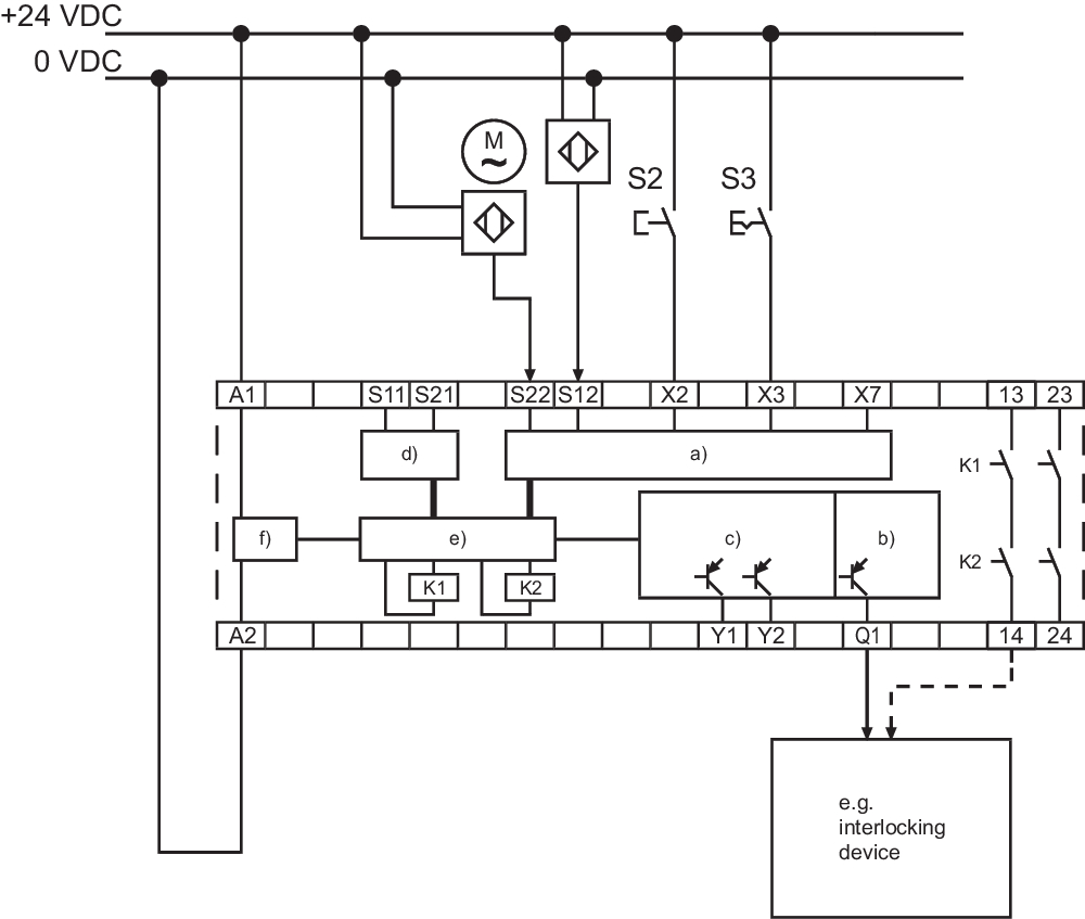
Wiring example
Video ID: Mr-Safety-SRB-E-Stillstand
(Vimeo)

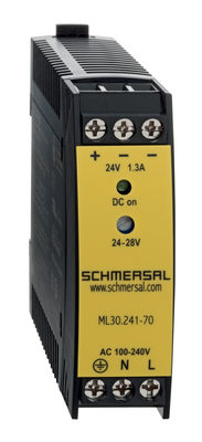
103015923 ML30.241-70
- 1-phase DIN rail power supplies
- AC 100-240V Wide-range input
- DC Output 24-28VDC / 1,3-1,1A / 30W
- Efficiency up to 89,4%
- Width only 22,5mm
| EU-Konformitätserklärung |  |
| Original | K.A. Schmersal GmbH & Co. KG Möddinghofe 30 42279 Wuppertal Germany Internet: www.schmersal.com |
| Erklärung: | Hiermit erklären wir, dass die nachfolgend aufgeführten Bauteile aufgrund der Konzipierung und Bauart den Anforderungen der unten angeführten Europäischen Richtlinien entsprechen. |
| Bezeichnung des Bauteils: | SRB-E-302FWS-TS |
| Typ: | siehe Typenschlüssel |
| Beschreibung des Bauteils: | Sicheres Zeitrelais, Sicherer Stillstandswächter |
| Einschlägige Richtlinien: | Maschinenrichtlinie | 2006/42/EG |
| EMV-Richtlinie | 2014/30/EU | |
| RoHS-Richtlinie | 2011/65/EU |
| Angewandte Normen: | EN ISO 13849-1:2015 EN ISO 13849-2:2012 IEC 61508 Teile 1-7:2010 EN 62061:2005 + AC:2010 + A1:2013 + A2:2015 |
| Benannte Stelle für die Zertifizierung des QS-Systems nach Anhang X, 2006/42/EG: | TÜV Rheinland Industrie Service GmbH Am Grauen Stein, 51105 Köln Kenn-Nr.: 0035 |
| Bevollmächtigter für die Zusammenstellung der technischen Unterlagen: | Oliver Wacker Möddinghofe 30 42279 Wuppertal |
| Ort und Datum der Ausstellung: | Wuppertal, 14. März 2023 |
 |
| Rechtsverbindliche Unterschrift Philip Schmersal Geschäftsführer |
Schmersal, Inc., 115 E Stevens Ave, Suite 208, Valhalla, NY 10595
The details and data referred to have been carefully checked. Images may diverge from original. Further technical data can be found in the manual. Technical amendments and errors possible.
Generated on: 4/24/2024, 6:05 PM