BN 120L-RZ 2,0M
BN 120L-RZ 2,0M
Downloads
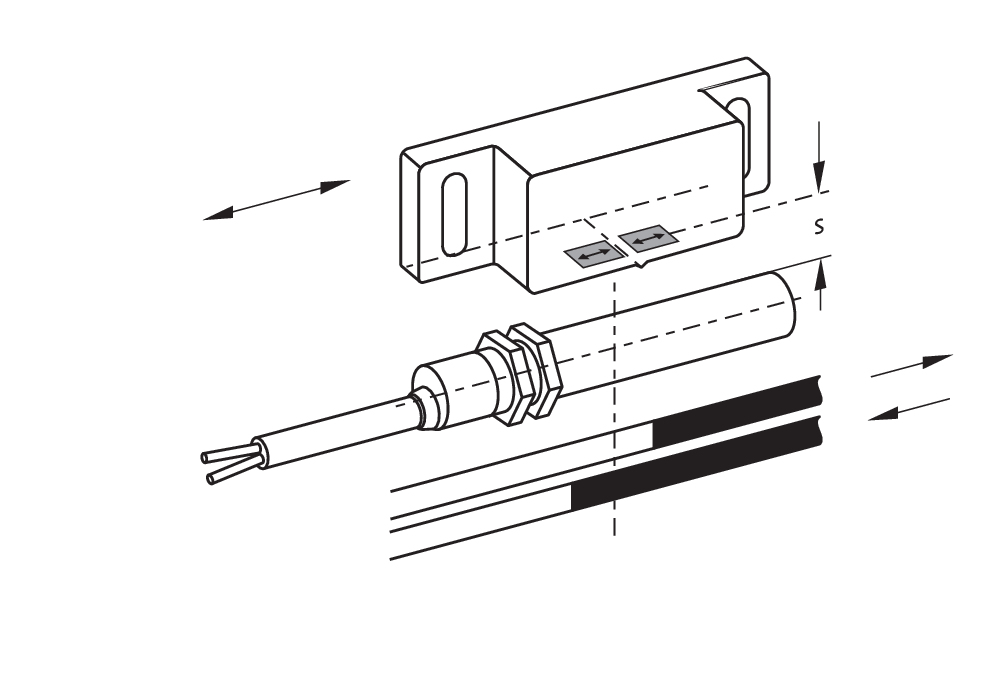
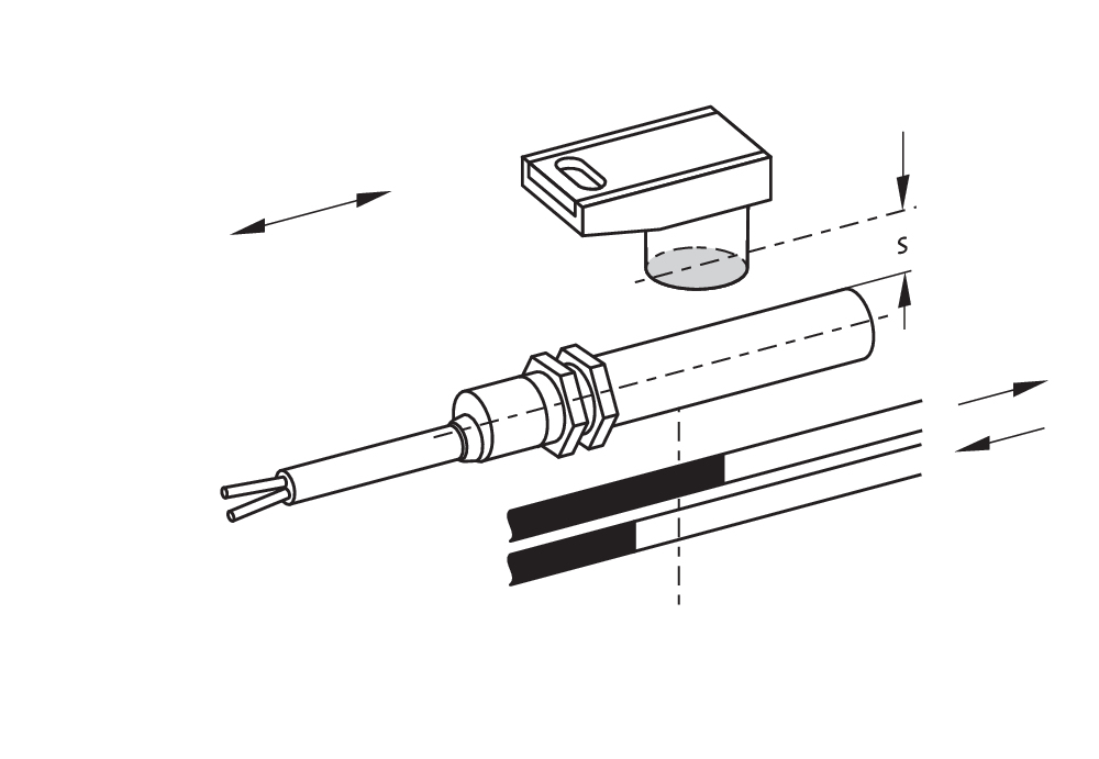
- Actuation from side
- with bias magnet
- Non-contact principle
- Long life
- Thermoplastic enclosure
- Actuating distance up to 60 mm depending on actuating magnet and version
- Design Ø 10.7 mm
- with central mounting
- With pre-wired cable
Ordering data
| Note (Delivery capacity) |
Ei saatavana! |
| Product type description |
BN 120L-RZ 2,0M |
| Article number (order number) |
101210879 |
| EAN (European Article Number) |
4030661388489 |
| eCl@ss number, version 12.0 |
27-27-43-02 |
| eCl@ss number, version 11.0 |
27-27-01-05 |
| eCl@ss number, version 9.0 |
27-27-01-05 |
| ETIM number, version 7.0 |
EC002544 |
| ETIM number, version 6.0 |
EC002544 |
General data
| Working principle |
magneettinen |
| Housing construction form |
sylinteri, kierre |
| Housing material |
Muovi, lasikuituvahvistettu kestomuoviMuovi, lasikuituvahvistettu kestomuovi |
| Gross weight |
70 g |
General data - Features
| Latching |
Kyllä |
| Suitable for elevators |
Kyllä |
| bias magnet |
Kyllä |
| Number of snap-in contacts |
1 |
Mechanical data
| Actuating panels |
sivulta |
| Actuating element |
Solenoidi |
| Mechanical life, minimum |
10 000 000 Operations |
| Actuating speed, maximum |
18 m/s |
| Mounting |
keskellä laippakierteillä M12 x 1 |
| Tightening torque of nuts, maximum |
0,9 Nm |
Mechanical data - Switching distances
| Switching distance Sn |
15 mm … 60 mm BP 10N = 15 mm BP 10S = 15 mm 2 x BP 10N = 20 mm 2 x BP 10S = 20 mm BP 15N = 17 mm BP 15S = 17 mm 2 x BP 15/2N = 22 mm 2 x BP 15/2S = 22 mm BP 34N = 10 ... 30 mm BP 34S = 15 ... 30 mm BP 20N = 25 mm BP 20S = 25 mm BP 31N = 25 mm BP 31S = 25 mm BP 11N = 15 mm BP 11S = 15 mm 2 x BP 11N = 25 mm 2 x BP 11S = 25 mm BP 12N = 20 mm BP 12S = 20 mm 2 x BP 12N = 10 ... 30 mm 2 x BP 12S = 10 ... 30 mm BP 21N = 15 ... 45 mm BP 21S = 15 ... 45 mm 2 x BP 21N = 20 ... 60 mm 2 x BP 21S = 20 ... 60 mm BE 20N = 20 mm BE 20S = 20 mm |
| Note (Switching distance Sn) |
Tunnistusetäisyys enint. 60 mm riippuen magneetista ja mallista Kytkentäetäisyyksiin liittyvät tekniset tiedot pätevat yksittäisille laitteille ilman ferromagneettista vaikutusta. Kaikki etäisyyden positiiviset ja negatiiviset muutokset ovat mahdollisia ulkoisten ferromagneettisen tekijöiden johdosta. Useita magneetteja käytettäessä tulee huomioida keskinäiset häiriöt. |
| Note (switching distance) |
All switching distances in accordance EN IEC 60947-5-2 |
| Repeat accuracy R |
0,3 mm |
Mechanical data - Connection technique
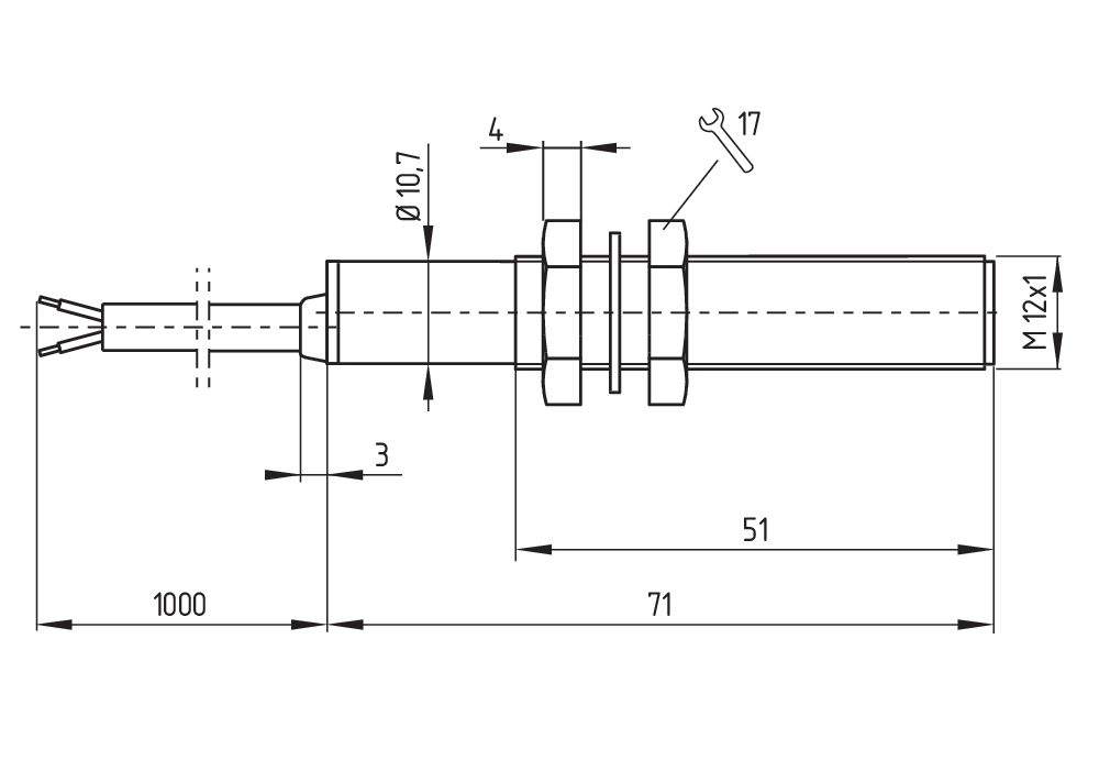
| Length of cable |
2 m |
| Termination |
kaapeli |
| Wire cross-section |
0,25 mm2 |
| Wire cross-section |
23 AWG |
| Material of the Cable mantle |
LiYY |
Mechanical data - Dimensions
| Diameter of sensor |
10,7 mm |
| width across flats |
17 BK |
| Length of sensor |
102 mm |
Ambient conditions
| Degree of protection |
IP67 |
| Ambient temperature |
-25 ... +70 °C |
| Resistance to vibrations |
10 … 55 Hz, Amplitudi 1 mm |
| Restistance to shock |
30 g / 11 ms |
Electrical data
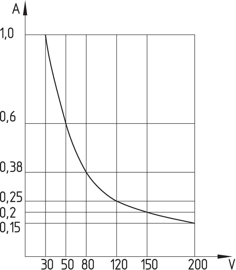
| Switching voltage, maximum |
200 VAC |
| Switching voltage, maximum |
200 VDC |
| Switching current, maximum |
1 A |
| Switching capacity, maximum |
30 W |
| Switching capacity, maximum |
30 VA |
| Switching element |
bistabiilinen kosketin |
Electrical data - Digital Output
| Design of control elements |
Reed -koskettimet |
Scope of delivery
| Scope of delivery |
Actuator must be ordered separately. |
Accessory
| Recommendation (actuator) |
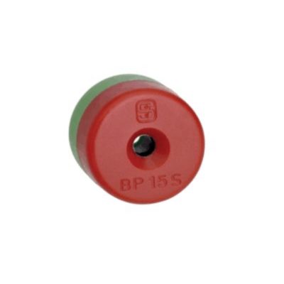
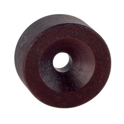
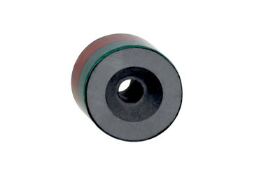
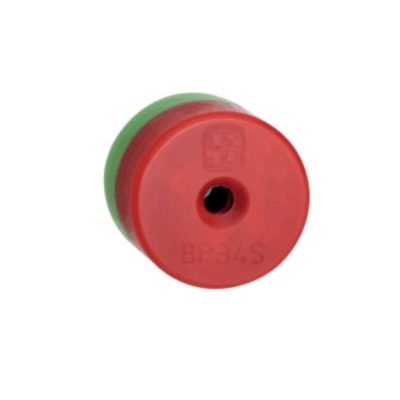
BP 10 S 2x BP 10 S BP 15 S BP 34 S BP 20 S BP 31 S BP 11 S 2x BP 11 S BP 12 S BP 21 S 2x BP 21 S BE 20 S BP 10 N 2x BP 10 N BP 15 N 2 x BP 15/2 N 2x BP 15/2 S BP 34 N BP 20 N BP 31 N BP 11 N 2x BP 11 N BP 12 N 2x BP 12 N 2x BP 12 S BP 21 N 2x BP 21 N BE 20 N |
| Recommendation (actuator, lift switchgear) |
BP 10 2 x BP 15/2 2 x BP 15 2 x BP 10 BP 15 BP 34 |
Note
| Note (General) |
The opening and closing functions depend on the direction of actuation, the actuating magnets and the polarity of the actuating magnets. When the switches and actuators come together, the colours must coincide: Red (S) to red (S) and green (N) to green (N). This does not apply to the bistable contact. The switch is to be mounted on iron with a non-magnetic layer of at least 20 mm. |
Kielisuodatin
Tuotelehti
Asennus- ja kytkentäohjeet
EU-vaatimuksenmukaisuusvakuutus
Tiedote
Lattaa Adobe Readerin viimeisin versio
Tuotekuva( luettelokuva)
Perustuotteen mitat
Kosketinkaavio
Kosketinkaavio
Kytkentäkaavio
Kytkentäkaavio
Schmersal India Pvt. Ltd., Plot No - G-7/1, Ranjangaon MIDC, Tal. - Shirur, Dist.- Pune 412 220
Tiedot ja arvot on tarkastettu huolellisesti. Kuvat voivat poiketa alkuperäisestä. Tarkemmat tekniset tiedot löytyvät manuaalista. Pidätämme oikeuden teknisiin muutoksiin ja virheisiin.
Luotu: 4.4.2025 22.49
.png?id=497683c97d2c2689df20070a5453bdbb)


