AES 7112.2 230 VAC
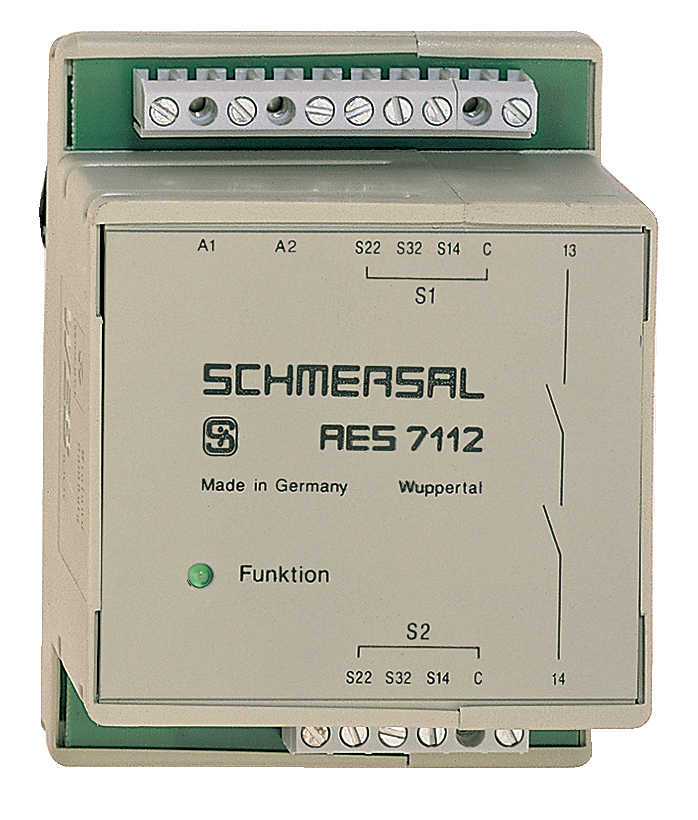
AES 7112.2 230 VAC
| Produkt-Typbezeichnung: AES 7112.(1) |
| (1) | |
| 1 | 110 VAC |
| 2 | 230 VAC |
| 3 | 24 VAC |
- Monitoring of BNS range magnetic safety sensors
- 1 safety contact, STOP 0
Ordering data
| Product type description |
AES 7112.2 230 VAC |
| Article number (order number) |
101115498 |
| EAN (European Article Number) |
4030661058474 |
| eCl@ss number, version 12.0 |
27-37-18-19 |
| eCl@ss number, version 11.0 |
27-37-18-19 |
| eCl@ss number, version 9.0 |
27-37-18-19 |
| ETIM number, version 7.0 |
EC001449 |
| ETIM number, version 6.0 |
EC001449 |
Approvals - Standards
| Certificates |
cULus |
General data
| Standards |
BG-GS-ET-14 BG-GS-ET-20 EN IEC 62061 EN ISO 13849-1 EN IEC 60947-5-1 EN IEC 60947-5-3 EN IEC 60947-5-5 EN IEC 60204-1 EN IEC 60947-1 |
| Housing material |
Kunststoff, glasfaserverstärkter Thermoplast, belüftet |
| Gross weight |
284 g |
General data - Features
| Wire breakage detection |
Ja |
| Cross-circuit detection |
Ja |
| Automatic reset function |
Ja |
| Reset after disconnection of supply voltage |
Ja |
| Integral system diagnostics, status |
Ja |
| Number of LEDs |
1 |
| Number of normally closed (NC) |
2 |
| Number of normally open (NO) |
4 |
| Number of safety contacts |
1 |
| Safety classification |
| Vorschriften |
EN ISO 13849-1 EN IEC 61508 |
| Stop-Category |
0 |
| Safety classification - Relay outputs |
| Performance Level, up to |
d |
| Category |
3 |
| PFH value |
1,00 x 10⁻⁷ /h |
| Notice |
bis max. 50.000 Schaltzyklen/Jahr und bei max. 80% Kontaktlast |
| Safety Integrity Level (SIL), suitable for applications in |
2 |
| Mission time |
20 Year(s) |
Mechanical data
| Mechanical life, minimum |
3.000.000 Operations |
| Mounting |
Schnellbefestigung für Normschiene nach DIN EN 60715 |
Mechanical data - Connection technique
| Termination |
starr oder flexibel Schraubanschluss M20 x 1.5 |
| Cable section, maximum |
1,5 mm² |
Mechanical data - Dimensions
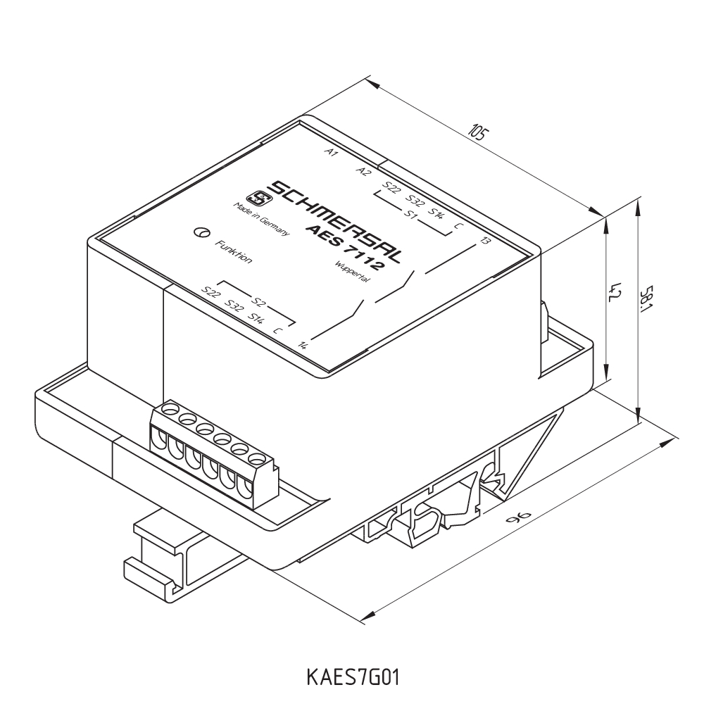
| Width |
105 mm |
| Height |
96 mm |
| Depth |
58 mm |
Ambient conditions
| Degree of protection of the enclosure |
IP40 |
| Degree of protection of the mounting space |
IP54 |
| Degree of protection of clips or terminals |
IP20 |
| Ambient temperature |
+0 ... +55 °C |
| Storage and transport temperature |
-25 ... +70 °C |
| Resistance to vibrations |
10 ... 55 Hz, Amplitude 0,35 mm, ± 15 % |
| Restistance to shock |
30 g / 11 ms |
Ambient conditions - Insulation values
| Rated impulse withstand voltage Uimp |
4 kV |
| Overvoltage category |
III |
| Degree of pollution |
2 |
Electrical data
| Frequency range |
50 Hz 60 Hz |
| Thermal test current |
5 A |
| Rated operating voltage |
230 VAC |
| Rated AC voltage for controls, 50 Hz, minimum |
195,5 VAC |
| Rated control voltage at AC 50 Hz, maximum |
253 VAC |
| Rated AC voltage for controls, 60 Hz, minimum |
195,5 VAC |
| Rated control voltage at AC 60 Hz, maximum |
253 VAC |
| Electrical power consumption |
1,5 W |
| Contact resistance, maximum |
0,1 Ω |
| Note (Contact resistance) |
in Neuzustand |
| Drop-out delay in case of power failure, typically |
80 ms |
| Drop-out delay in case of emergency, typically |
20 ms |
| Pull-in delay at automatic start, maximum, typically |
100 ms |
| Pull-in delay at RESET, typically |
20 ms |
| Material of the contacts, electrical |
AgSn0 |
Electrical data - Safe relay outputs
| Voltage, Utilisation category AC-15 |
250 VAC |
| Current, Utilisation category AC-15 |
2 A |
| Voltage, Utilisation category DC-13 |
24 VDC |
| Current, Utilisation category DC-13 |
2 A |
| Switching capacity, minimum |
10 VDC |
| Switching capacity, minimum |
10 mA |
| Switching capacity, maximum |
250 VAC |
| Switching capacity, maximum |
8 A |
Electrical data - Digital inputs
| Conduction resistance, maximum |
40 Ω |
Electrical data - Digital Output
| Voltage, Utilisation category DC-12 |
24 VDC |
| Current, Utilisation category DC-12 |
0,1 A |
Electrical data - Relay outputs (auxiliary contacts)
| Switching capacity, maximum |
24 VDC |
| Switching capacity, maximum |
2 A |
Electrical data - Electromagnetic compatibility (EMC)
| EMC rating |
EMV-Richtlinie |
Status indication
| Indicated operating states |
Freigabe |
Other data
| Note (applications) |
Sicherheits-Sensor Schutzeinrichtung |
Note
| Note (General) |
Induktive Verbraucher (Schütze, Relais etc.) sind durch eine geeignete Beschaltung zu entstören. |
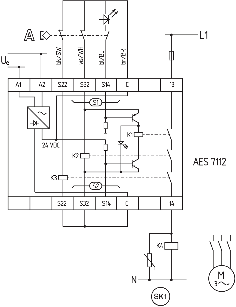
Wiring example
| Note (Wiring diagram) |
Das Schaltungsbeispiel ist bei geschlossenen Schutzeinrichtungen und im spannungslosen Zustand dargestellt. Überwachung von 1 Schutzeinrichtung(en) mit je einem magnetischen Sicherheits-Sensor der Reihe BNS Überwachung von weiteren Schutzeinrichtungen: An S2 können analog zu S1 weitere magnetische Sicherheits-Sensoren angeschlossen werden. Zur Absicherung einer Schutzeinrichtung bis zu PL c und Kategorie 1 |
Sprachfilter
Datenblatt
Betriebsanleitung und Konformitätserklärung
UL-Zertifikat
Schaltungsbeispiel (elektr. Verdrahtung)
SISTEMA-VDMA Bibliothek/Library
Download der aktuellen Version von Adobe Reader
Produktbild (Katalogeinzelphoto )
Maßzeichnung Grundgerät
Schaltungsbeispiel
| EU-Konformitätserklärung |  |
| Original | K.A. Schmersal GmbH & Co. KG Möddinghofe 30 42279 Wuppertal Germany Internet: www.schmersal.com |
| Erklärung: | Hiermit erklären wir, dass die nachfolgend aufgeführten Bauteile aufgrund der Konzipierung und Bauart den Anforderungen der unten angeführten Europäischen Richtlinien entsprechen. |
| Bezeichnung des Bauteils: | AES 7112 AES 7112.3-2261 |
| Typ: | siehe Typenschlüssel |
| Beschreibung des Bauteils: | Auswerteeinheit für berührungslos wirkenden Sicherheitsschalter und Relais-Sicherheitskombination in Verbindung mit den Magnetsicherheitsschaltern Reihe BNS |
| Einschlägige Richtlinien: | Maschinenrichtlinie | 2006/42/EG |
| EMV-Richtlinie | 2014/30/EU | |
| RoHS-Richtlinie | 2011/65/EU |
| Angewandte Normen: | EN 60947-5-3:2013 EN ISO 13849-1:2015 EN ISO 13849-2:2012 |
| Benannte Stelle für die Zertifizierung des QS-Systems nach Anhang X, 2006/42/EG: | TÜV Rheinland Industrie Service GmbH Am Grauen Stein, 51105 Köln Kenn-Nr.: 0035 |
| Bevollmächtigter für die Zusammenstellung der technischen Unterlagen: | Oliver Wacker Möddinghofe 30 42279 Wuppertal |
| Ort und Datum der Ausstellung: | Wuppertal, 16. Dezember 2021 |
 |
| Rechtsverbindliche Unterschrift Philip Schmersal Geschäftsführer |
Schmersal India Pvt. Ltd., Plot No - G-7/1, Ranjangaon MIDC, Tal. - Shirur, Dist.- Pune 412 220
Die genannten Daten und Angaben wurden sorgfältig geprüft. Abbildungen können vom Original abweichen. Weitere technische Daten finden Sie in der Betriebsanleitung. Technische Änderungen und Irrtümer vorbehalten.
Generiert am: 01.05.2025, 10:37