AES 7112.3 24 VAC
AES 7112.3 24 VAC
| Désignation produit: AES 7112.(1) |
| (1) | |
| 1 | 110 VAC |
| 2 | 230 VAC |
| 3 | 24 VAC |
- Monitoring of BNS range magnetic safety sensors
- 1 safety contact, STOP 0
Ordering data
| Product type description |
AES 7112.3 24 VAC |
| Article number (order number) |
101120016 |
| EAN (European Article Number) |
4030661058641 |
| eCl@ss number, version 12.0 |
27-37-18-19 |
| eCl@ss number, version 11.0 |
27-37-18-19 |
| eCl@ss number, version 9.0 |
27-37-18-19 |
| ETIM number, version 7.0 |
EC001449 |
| ETIM number, version 6.0 |
EC001449 |
Approvals - Standards
| Certificates |
cULus |
General data
| Standards |
BG-GS-ET-14 BG-GS-ET-20 EN IEC 62061 EN ISO 13849-1 EN IEC 60947-5-1 EN IEC 60947-5-3 EN IEC 60947-5-5 EN IEC 60204-1 EN IEC 60947-1 |
| Housing material |
Plastique, thermoplastique renforcée de fibres de verre, ventilée |
| Gross weight |
140 g |
General data - Features
| Wire breakage detection |
Oui |
| Cross-circuit detection |
Oui |
| Automatic reset function |
Oui |
| Reset after disconnection of supply voltage |
Oui |
| Integral system diagnostics, status |
Oui |
| Number of LEDs |
1 |
| Number of normally closed (NC) |
2 |
| Number of normally open (NO) |
4 |
| Number of safety contacts |
1 |
| Safety classification |
| Vorschriften |
EN ISO 13849-1 EN IEC 61508 |
| Stop-Category |
0 |
| Safety classification - Relay outputs |
| Performance Level, up to |
d |
| Category |
3 |
| PFH value |
1,00 x 10⁻⁷ /h |
| Notice |
applicable pour les applications jusqu'à max. 50 000 manoeuvres/an et une charge de contact de 80% max. |
| Safety Integrity Level (SIL), suitable for applications in |
2 |
| Mission time |
20 Year(s) |
Mechanical data
| Mechanical life, minimum |
3 000 000 Operations |
| Mounting |
Fixation rapide sur rails DIN standards selon DIN EN 60715 |
Mechanical data - Connection technique
| Termination |
rigide ou flexible Raccord fileté M20 x 1.5 |
| Cable section, maximum |
1,5 mm² |
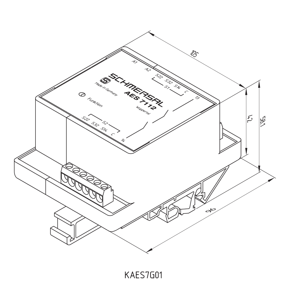
Mechanical data - Dimensions
| Width |
105 mm |
| Height |
96 mm |
| Depth |
58 mm |
Ambient conditions
| Degree of protection of the enclosure |
IP40 |
| Degree of protection of the mounting space |
IP54 |
| Degree of protection of clips or terminals |
IP20 |
| Ambient temperature |
+0 ... +55 °C |
| Storage and transport temperature |
-25 ... +70 °C |
| Resistance to vibrations |
10...55 Hz, amplitude 0,35 mm, ± 15 % |
| Restistance to shock |
30 g / 11 ms |
Ambient conditions - Insulation values
| Rated impulse withstand voltage Uimp |
4 kV |
| Overvoltage category |
III |
| Degree of pollution |
2 |
Electrical data
| Frequency range |
50 Hz 60 Hz |
| Thermal test current |
5 A |
| Rated operating voltage |
24 VAC |
| Rated AC voltage for controls, 50 Hz, minimum |
20,4 VAC |
| Rated control voltage at AC 50 Hz, maximum |
26,4 VAC |
| Rated AC voltage for controls, 60 Hz, minimum |
20,4 VAC |
| Rated control voltage at AC 60 Hz, maximum |
26,4 VAC |
| Electrical power consumption |
1,5 W |
| Contact resistance, maximum |
0,1 Ω |
| Note (Contact resistance) |
à l'état neuf |
| Drop-out delay in case of power failure, typically |
80 ms |
| Drop-out delay in case of emergency, typically |
20 ms |
| Pull-in delay at automatic start, maximum, typically |
100 ms |
| Pull-in delay at RESET, typically |
20 ms |
| Material of the contacts, electrical |
AgSn0 |
Electrical data - Safe relay outputs
| Voltage, Utilisation category AC-15 |
250 VAC |
| Current, Utilisation category AC-15 |
2 A |
| Voltage, Utilisation category DC-13 |
24 VDC |
| Current, Utilisation category DC-13 |
2 A |
| Switching capacity, minimum |
10 VDC |
| Switching capacity, minimum |
10 mA |
| Switching capacity, maximum |
250 VAC |
| Switching capacity, maximum |
8 A |
Electrical data - Digital inputs
| Conduction resistance, maximum |
40 Ω |
Electrical data - Digital Output
| Voltage, Utilisation category DC-12 |
24 VDC |
| Current, Utilisation category DC-12 |
0,1 A |
Electrical data - Relay outputs (auxiliary contacts)
| Switching capacity, maximum |
24 VDC |
| Switching capacity, maximum |
2 A |
Electrical data - Electromagnetic compatibility (EMC)
| EMC rating |
Directive CEM |
Status indication
| Indicated operating states |
Sortie active |
Other data
| Note (applications) |
Capteur de sécurité Dispositif de protection |
Note
| Note (General) |
Des charges inductives (p.ex. relais externe, etc.) doivent être antiparasitées par un dispositif approprié. |
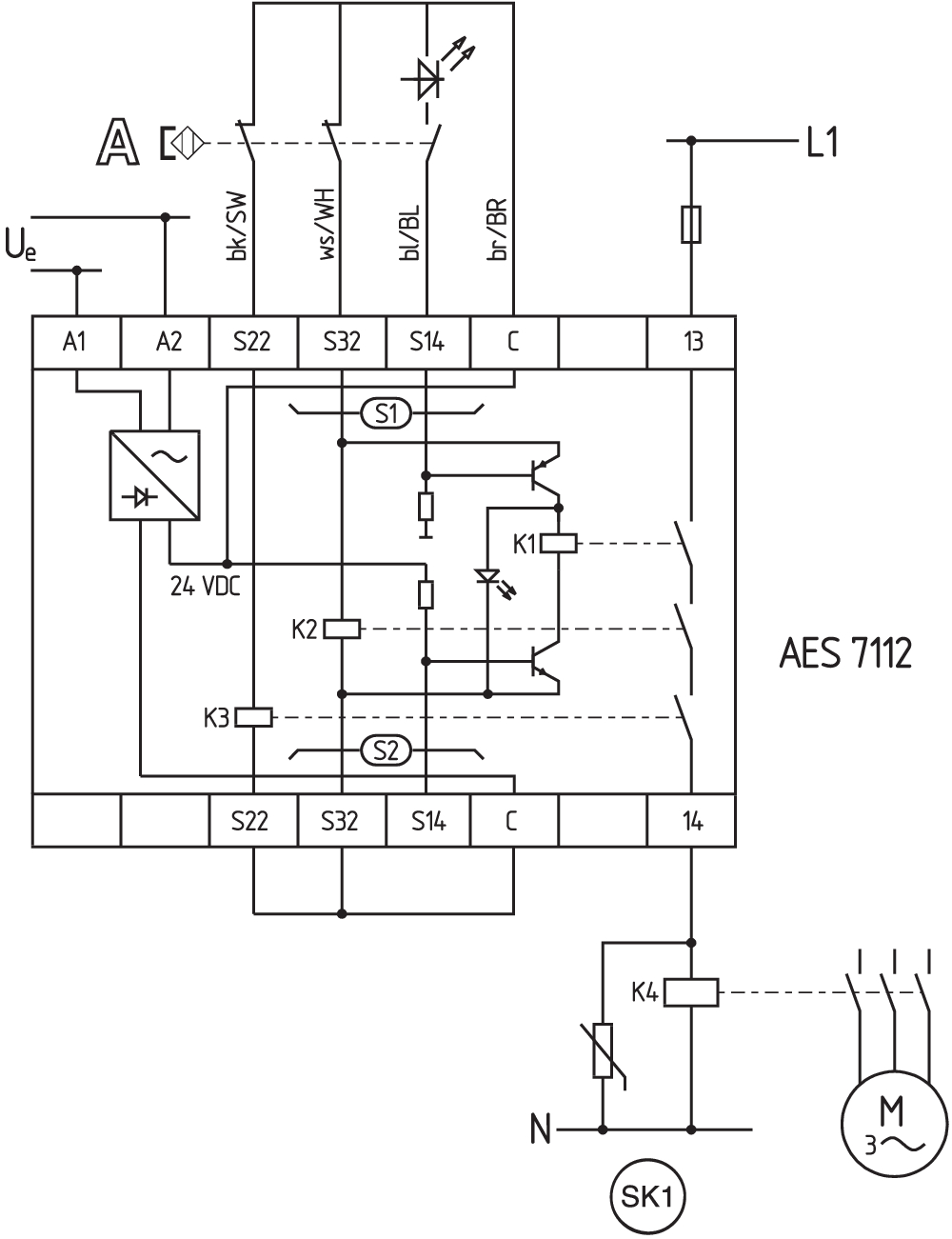
Wiring example
| Note (Wiring diagram) |
L'exemple de câblage est représenté pour les protecteurs fermés et hors tension. Surveillance de 1 protecteur(s) avec chacun un capteur de sécurité magnétique de la série BNS Surveillance d'autres protecteurs: par analogie avec S1, d'autres capteurs magnétiques de sécurité peuvent être raccordés aux S2. Pour la surveillance d'un protecteur jusqu'à max. PL c et catégorie 1 |
Filtre de langue
Fiches techniques
Mode d'emploi et déclaration de conformité
Certificat UL
Exemple de câblage (câblage électrique)
Bibliothèque/Library SISTEMA-VDMA
Télécharger la dernière version d'Adobe Reader
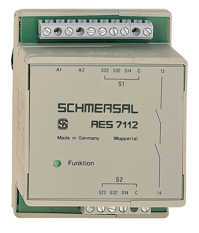
Photo du produit (photo individuelle de catalogue)
Plan d'encombrement composant de base
Exemple de câblage
| EU Declaration of Conformity |  |
| Original | K.A. Schmersal GmbH & Co. KG Möddinghofe 30 42279 Wuppertal Germany Internet: www.schmersal.com |
| Declaration: | We hereby certify that the hereafter described components both in their basic design and construction conform to the applicable European Directives. |
| Name of the component: | AES 7112 AES 7112.3-2261 |
| Type: | See ordering code |
| Description of the component: | Safety-monitoring module for non-contact safety switches and safety relay combination in connection with the BNS series magnetic safety switches |
| Relevant Directives: | Machinery Directive | 2006/42/EC |
| EMC-Directive | 2014/30/EU | |
| RoHS-Directive | 2011/65/EU |
| Applied standards: | EN 60947-5-3:2013 EN ISO 13849-1:2015 EN ISO 13849-2:2012 |
| Notified body, which approved the full quality assurance system, referred to in Appendix X, 2006/42/EC: | TÜV Rheinland Industrie Service GmbH Am Grauen Stein, 51105 Köln ID n°: 0035 |
| Person authorised for the compilation of the technical documentation: | Oliver Wacker Möddinghofe 30 42279 Wuppertal |
| Place and date of issue: | Wuppertal, December 16, 2021 |
 |
| Authorised signature Philip Schmersal Managing Director |
Schmersal India Pvt. Ltd., Plot No - G-7/1, Ranjangaon MIDC, Tal. - Shirur, Dist.- Pune 412 220
Les données et les valeurs ont été soigneusement vérifiées. Les illustrations peuvent être différentes de l'original. Vous trouverez d'avantage de caractéristiques techniques dans les manuels d’instructions. Sous réserve de modifications techniques et errata.
Généré le: 07/05/2025 02:38