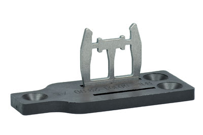
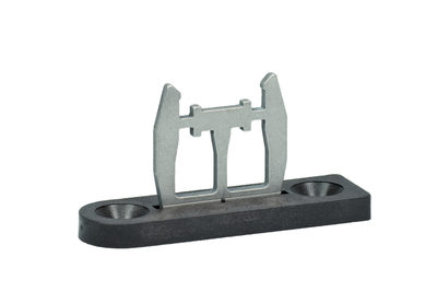
AZM 161 Z ST1-AS PT
AZM 161 Z ST1-AS PT
| Produkt-Typbezeichnung: AZM 161 (1) (2)-AS (3)(4)(5)(6) |
| (1) | |
| Z | Zuhaltungsüberwachung > |
| B | Betätigerüberwachung |
| BZ | Betätiger/Zuhaltung kombiniert überwacht |
| (2) | |
| ST1 | Stecker unten |
| ST2 | Stecker rechts |
| (3) | |
| ohne | Rastkraft 5 N |
| R | Rastkraft 30 N |
| (4) | |
| ohne | Ruhestromprinzip |
| A | Arbeitsstromprinzip |
| (5) | |
| ohne | Magnetversorgung AUS AS-Interface |
| P | Magnetversorgung AUS 24 VDC (Aux) |
| (6) | |
| ohne | Hilfsentriegelung |
| N | Notentsperrung |
| T | Fluchtentriegelung |
- Solenoid supply 24 VDC (Aux)
- Guard locking monitored
- Emergency exit
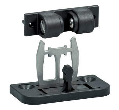
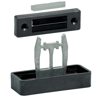
- Solenoid interlock
- Thermoplastic enclosure
- High holding force 2000
- 130 mm x 90 mm x 30 mm
- Interlock with protection against incorrect locking.
- Double-insulated
- Long life
- Integrated AS-Interface
Ordering data
| Product type description |
AZM 161 Z ST1-AS PT |
| Article number (order number) |
101209115 |
| EAN (European Article Number) |
4030661404110 |
| eCl@ss number, version 12.0 |
27-27-26-03 |
| eCl@ss number, version 11.0 |
27-27-26-03 |
| eCl@ss number, version 9.0 |
27-27-26-03 |
| ETIM number, version 7.0 |
EC002593 |
| ETIM number, version 6.0 |
EC002593 |
Approvals - Standards
| Certificates |
cULus ASi-SaW |
General data
| Standards |
EN IEC 62026-2 EN ISO 13849-1 EN IEC 60947-5-1 EN IEC 61508 |
| Coding level according to EN ISO 14119 |
gering |
| Working principle |
elektromechanisch |
| Housing material |
Kunststoff, glasfaserverstärkter Thermoplast, selbstverlöschend |
| Reaction time, maximum |
100 ms |
| Gross weight |
465 g |
General data - Features
| Power to unlock |
Ja |
| Solenoid interlock monitored |
Ja |
| Emergency exit |
Ja |
| Integral system diagnostics, status |
Ja |
| Number of actuating directions |
3 |
| Safety classification |
| Vorschriften |
EN ISO 13849-1 EN IEC 61508 |
| Performance Level, up to |
c |
| Category |
1 |
| PFH value |
1,14 x 10⁻⁶ /h |
| Note (PFH-value) |
bis max. 100.000 Schaltzyklen/Jahr |
| Safety Integrity Level (SIL), suitable for applications in |
1 |
| Mission time |
20 Year(s) |
| Safety classification - Fault exclusion |
| Please note: |
Einsetzbar wenn ein Fehlerausschluss für eine gefahrbringende Beschädigung der 1-kanaligen Mechanik zulässig ist und ein ausreichender Manipulationsschutz gewährleistet ist. |
| Performance Level, up to |
d |
| Category |
3 |
| PFH value |
1,01 x 10⁻⁷ /h |
| Note (PFH-value) |
bis max. 100.000 Schaltzyklen/Jahr |
| Safety Integrity Level (SIL), suitable for applications in |
2 |
| Mission time |
20 Year(s) |
Safety classification - Guard locking function
| Performance Level, up to |
e |
| Note (Performance Level) |
Informationen für die Sicherheitsbetrachtung der Zuhaltefunktion sind in der Betriebsanleitung oder in der Anleitung „Betrieb und Montage“ dokumentiert. |
Mechanical data
| Mechanical lifetime, minimum |
1.000.000 Operations |
| Actuating play in direction of actuation |
5,5 mm |
| Holding force FZh in accordance with EN ISO 14119 |
2.000 N |
| Holding force Fmax, maximum |
2.600 N |
| Latching force |
5 N |
| Actuating speed, maximum |
2 m/s |
| Mounting |
Schrauben |
| Type of the fixing screws |
3x M6 |
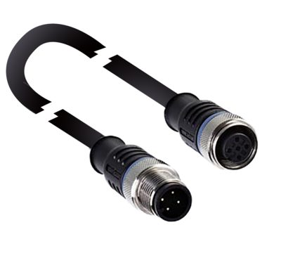
Mechanical data - Connection technique
| Connector position |
Mittig |
| Termination |
Einbaustecker M12, 4-polig, A-Codierung |
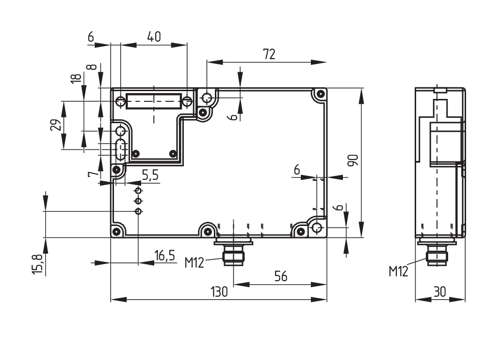
Mechanical data - Dimensions
| Length of sensor |
30 mm |
| Width of sensor |
130 mm |
| Height of sensor |
90 mm |
Ambient conditions
| Degree of protection |
IP67 |
| Ambient temperature |
-25 ... +60 °C |
| Storage and transport temperature |
-25 ... +85 °C |
| Relative humidity, minimum |
30 % |
| Relative humidity, maximum |
95 % |
| Note (Relative humidity) |
nicht kondensierend nicht vereisend |
| Resistance to vibrations |
10 … 150 Hz, Amplitude 0,35 mm |
| Restistance to shock |
30 g / 11 ms |
| Protection class |
II |
| Permissible installation altitude above sea level, maximum |
2.000 m |
Ambient conditions - Insulation values
| Rated insulation voltage Ui |
32 VDC |
| Rated impulse withstand voltage Uimp |
0,8 kV |
| Overvoltage category |
III |
| Degree of pollution |
3 |
Electrical data
| Maximale Schalthäufigkeit |
1.000 /h |
Electrical data - AS Interface
| Rated operating voltage |
26,5 ... 31,6 VDC (Verpolungsschutz) |
| AS-i Current consumption, maximum |
100 mA |
Electrical data - AS-Interface specification
| AS-i Specification |
Safety-Slave |
| AS-i Version |
V 2.1 |
| AS-i Profile |
S-7.B.F.E |
| AS-i, IO-Code |
0x7 |
| AS-i, ID-Code |
0xB |
| AS-i, ID-Code1 |
0xF |
| AS-i, ID-Code2 |
0xE |
| AS-i Input, Channel 1 |
Datenbits DI 0/DI 1 = dynamische Codeübertragung |
| AS-i Input, Channel 2 |
Datenbits DI 2/DI 3 = dynamische Codeübertragung |
| AS-i Outputs, DO 0 |
Magnetansteuerung |
| AS-i Outputs, DO 1 |
Keine Funktion |
| AS-i Outputs, DO 2 |
Keine Funktion |
| AS-i Outputs, DO 3 |
Keine Funktion |
| AS-i Parameter bits, P0 |
Betätiger erkannt |
| AS-i Parameter bits, P1 |
Zuhaltung gesperrt |
| AS-i Parameter bits, P2 |
Magnetspannung im Toleranzbereich |
| AS-i Parameter bits, P3 |
Fehler - Sperren/Entsperren der Zuhaltung blockiert |
| Note (AS-i Parameter bits) |
Parameterausgänge sind auf „1111“ (0xF) einzustellen FID: Peripheriefehler |
| AS-i Input module address |
0 |
| Note (AS-i Input module address) |
Voreingestellt auf Adresse 0, änderbar über AS-Interface Busmaster oder Handprogrammiergerät |
Electrical data - Auxiliary voltage
| Operating voltage |
24 VDC -15 % / +10 % (stabilisiertes PELV-Netzteil) |
| Current consumption |
500 mA |
| Rated operating voltage |
24 VDC |
| Fuse rating |
4 A |
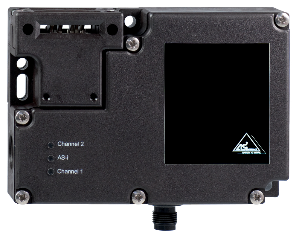
Status indication
| Note (LED switching conditions display) |
(1) gelbe LED: Kanal 2 / AS-i SaW Bit 2.3 (2) grün/rote LED (AS-i Duo LED): Versorgungsspannung / Kommunikationsfehler / Slaveadresse = 0 oder Peripheriefehler (3) gelbe LED: Kanal 1 / AS-i SaW Bit 0.1 |
Other data
| Note (applications) |
verschiebbare Schutzeinrichtung abnehmbare Schutzeinrichtung drehbare Schutzeinrichtung |
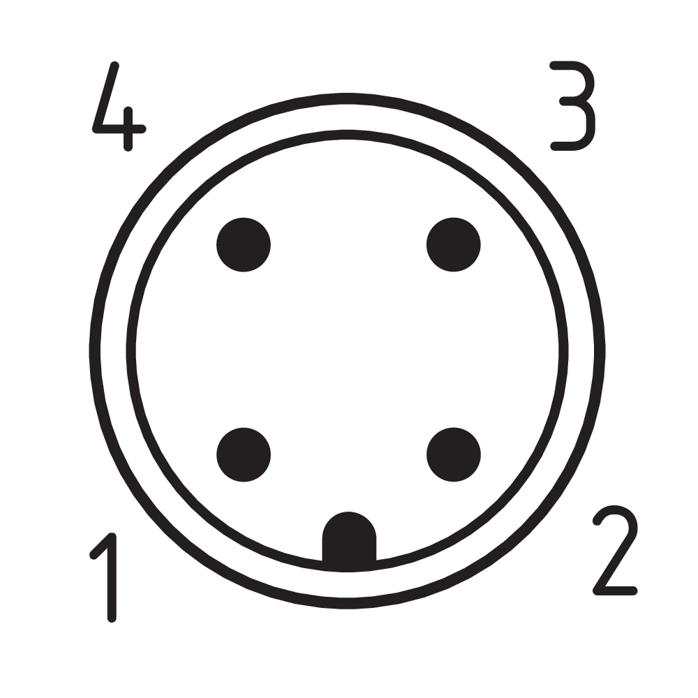
Pin assignment
| PIN 1 |
AS-i + |
| PIN 2 |
Aux - (P) |
| PIN 3 |
AS-Interface - |
| PIN 4 |
Aux + (P) |
Scope of delivery
| Scope of delivery |
Der Betätiger ist nicht im Lieferumfang enthalten. |
Note
| Note (General) |
Da bei Spannungsausfall bzw. Betätigen des Hauptschalters die Schutzeinrichtung unmittelbar geöffnet werden kann, dürfen die Sicherheitszuhaltungen mit Arbeitsstromprinzip nur in Sonderfällen nach strengen Bewertung des Unfallrisikos verwendet werden. |
| Note (Emergency exit) |
Im Notfall Betätigung innerhalb des Gefahrenbereiches |
| Note voltage AUX DC |
stabilisiertes PELV-Netzteil |
Sprachfilter
Datenblatt
Betriebsanleitung und Konformitätserklärung
UL-Zertifikat
AS-Interface at Work Zertifikat
SISTEMA-VDMA Bibliothek/Library
Download der aktuellen Version von Adobe Reader
Produktbild (Katalogeinzelphoto )
Maßzeichnung Grundgerät
Polbild
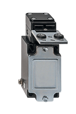
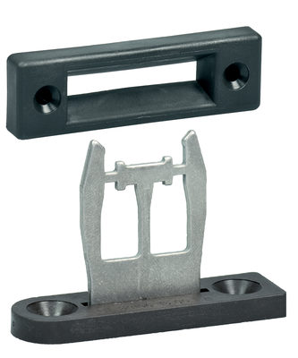
101145117 ACTUATOR AZM 161-B1
- Straight actuator
- Particularly suitable for sliding doors
101144416 ACTUATOR AZM 161-B1E
- Straight actuator
- Particularly suitable for sliding doors
101171859 ACTUATOR AZM 161-B1ES
- Straight actuator
- Particularly suitable for sliding doors

101175431 ACTUATOR AZM 161-B1F
- Straight actuator
- Particularly suitable for sliding doors
101171125 BETAETIGER AZM 161-B1S
- Straight actuator
- Particularly suitable for sliding doors
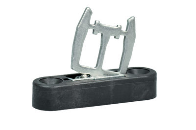
101173089 AZM 161-B1-2053 RETROFIT KIT
- Straight actuator
- Particularly suitable for sliding doors
- adjustable ball latch

101164100 AZM 161-B1-1747 RETROFIT KIT
- Straight actuator with magnetic latch
- Particularly suitable for sliding doors
101178199 AZM 161-B1-2024
- Straight actuator with slot lip-seal
- Particularly suitable for sliding doors
101176642 AZM 161-B1-2177 RETROFIT KIT
- Straight actuator with centering guide
- Particularly suitable for sliding doors

101174113 AZM 161-B6-2177 WITH CENTERING GUIDE
- For very smal actuating radii
101170375 BETAETIGER AZM 161-B6S
- For very smal actuating radii
101144420 ACTUATOR AZM 161-B6
- Flexible actuator
- Particularly suitable for hinged guards
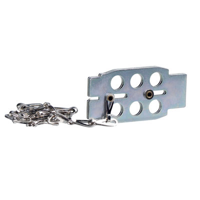
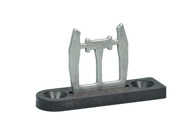
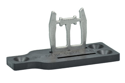
101110500 LOCKOUT TAG SZ 16/335
- To prevent inadvertent closing, e.g. during maintenance
- For complex plant
- Prevents actuation of the switch
- Up to 6 padlocks can be fitted
- The lockout tag can be mounted on a chain near to the safety switch
| EU-Konformitätserklärung |  |
| Original | K.A. Schmersal GmbH & Co. KG Möddinghofe 30 42279 Wuppertal Germany Internet: www.schmersal.com |
| Erklärung: | Hiermit erklären wir, dass die nachfolgend aufgeführten Bauteile aufgrund der Konzipierung und Bauart den Anforderungen der unten angeführten Europäischen Richtlinien entsprechen. |
| Bezeichnung des Bauteils: | AZM 161 AS |
| Typ: | siehe Typenschlüssel |
| Beschreibung des Bauteils: | Verriegelung mit elektromagnetischer Zuhaltung für Sicherheitsfunktionen mit integriertem AS-i Safety at Work |
| Einschlägige Richtlinien: | Maschinenrichtlinie | 2006/42/EG |
| EMV-Richtlinie | 2014/30/EU | |
| RoHS-Richtlinie | 2011/65/EU |
| Angewandte Normen: | EN 60947-5-1:2017 EN ISO 14119:2013 EN ISO 13849-1:2015 EN 61508 Teile 1-7:2010 |
| Bevollmächtigter für die Zusammenstellung der technischen Unterlagen: | Oliver Wacker Möddinghofe 30 42279 Wuppertal |
| Ort und Datum der Ausstellung: | Wuppertal, 3. August 2020 |
 |
| Rechtsverbindliche Unterschrift Philip Schmersal Geschäftsführer |
Schmersal India Pvt. Ltd., Plot No - G-7/1, Ranjangaon MIDC, Tal. - Shirur, Dist.- Pune 412 220
Die genannten Daten und Angaben wurden sorgfältig geprüft. Abbildungen können vom Original abweichen. Weitere technische Daten finden Sie in der Betriebsanleitung. Technische Änderungen und Irrtümer vorbehalten.
Generiert am: 10.08.2025, 08:03
Zuletzt angesehen