BN 120-RZ

BN 120-RZ
Downloads
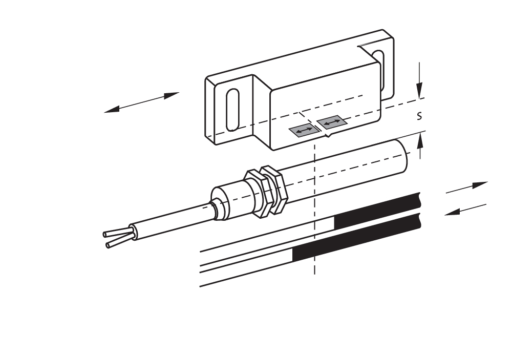
- Actuation from side
- with bias magnet
- Non-contact principle
- Long life
- Thermoplastic enclosure
- Actuating distance up to 60 mm depending on actuating magnet and version
- Design Ø 10.7 mm
- with central mounting
- With pre-wired cable
Ordering data
| Product type description |
BN 120-RZ |
| Article number (order number) |
101186843 |
| EAN (European Article Number) |
4030661335421 |
| eCl@ss number, version 12.0 |
27-27-43-02 |
| eCl@ss number, version 11.0 |
27-27-01-05 |
| eCl@ss number, version 9.0 |
27-27-01-05 |
| ETIM number, version 7.0 |
EC002544 |
| ETIM number, version 6.0 |
EC002544 |
General data
| Working principle |
magnetisch |
| Housing construction form |
Cilinder, schroefdraad |
| Housing material |
Kunststof, glasvezelversterkte thermoplast |
| Gross weight |
30 g |
General data - Features
| Latching |
Ja |
| Suitable for elevators |
Ja |
| bias magnet |
Ja |
| Number of snap-in contacts |
1 |
Mechanical data
| Actuating panels |
zijdelingse |
| Actuating element |
Magneet |
| Mechanical life, minimum |
10.000.000 Operations |
| Actuating speed, maximum |
18 m/s |
| Mounting |
Centraal met schroefdraadflens M12 x 1 |
| Tightening torque of nuts, maximum |
0,9 Nm |
Mechanical data - Switching distances
| Switching distance Sn |
15 mm … 60 mm BP 10N = 15 mm BP 10S = 15 mm 2 x BP 10N = 20 mm 2 x BP 10S = 20 mm BP 15N = 17 mm BP 15S = 17 mm 2 x BP 15/2N = 22 mm 2 x BP 15/2S = 22 mm BP 34N = 10 ... 30 mm BP 34S = 15 ... 30 mm BP 20N = 25 mm BP 20S = 25 mm BP 31N = 25 mm BP 31S = 25 mm BP 11N = 15 mm BP 11S = 15 mm 2 x BP 11N = 25 mm 2 x BP 11S = 25 mm BP 12N = 20 mm BP 12S = 20 mm 2 x BP 12N = 10 ... 30 mm 2 x BP 12S = 10 ... 30 mm BP 21N = 15 ... 45 mm BP 21S = 15 ... 45 mm 2 x BP 21N = 20 ... 60 mm 2 x BP 21S = 20 ... 60 mm BE 20N = 20 mm BE 20S = 20 mm |
| Note (Switching distance Sn) |
Schakelafstand tot 60 mm, afhankelijk van de bedieningsmagneet en uitvoering De opgegeven schakelafstanden gelden bij de bediening van individueel gemonteerde toestellen zonder ferromagnetische invloed. De afstand kan, positief of negatief, veranderen door ferromagnetische invloeden. Bij een opstelling van meerdere bedienmagneten moet er rekening gehouden worden met wederzijdse beïnvloeding. |
| Note (switching distance) |
All switching distances in accordance EN IEC 60947-5-2 |
| Repeat accuracy R |
0,3 mm |
Mechanical data - Connection technique
| Length of cable |
1 m |
| Termination |
Kabel |
| Wire cross-section |
0,25 mm2 |
| Wire cross-section |
23 AWG |
| Material of the Cable mantle |
LiYY |
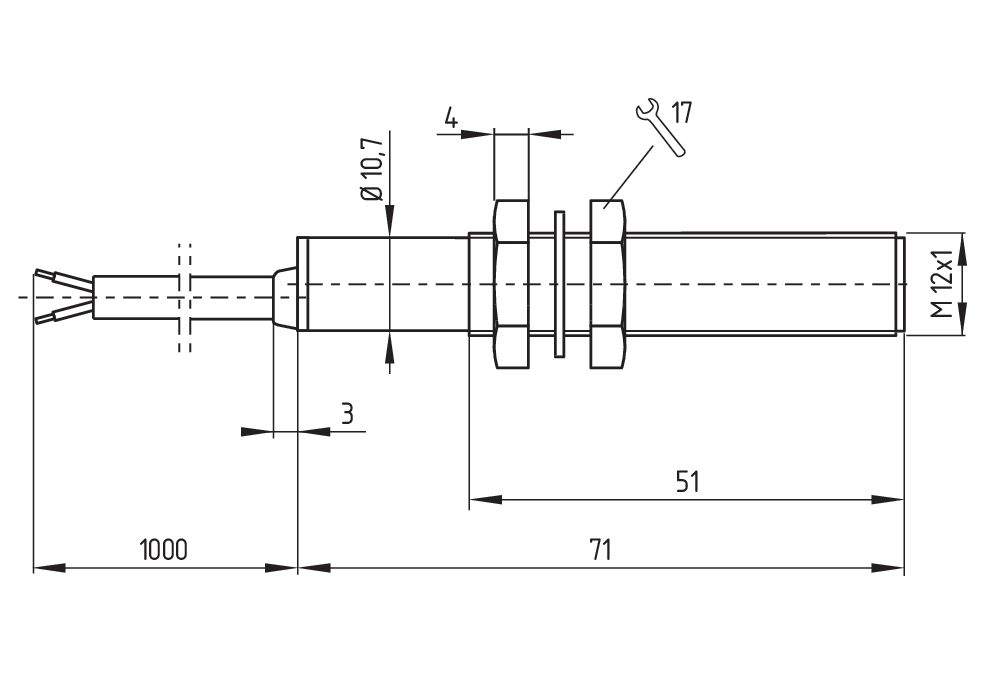
Mechanical data - Dimensions
| Diameter of sensor |
10,7 mm |
| Length of sensor |
71 mm |
Ambient conditions
| Degree of protection |
IP67 |
| Ambient temperature |
-25 ... +70 °C |
| Resistance to vibrations |
10…55 Hz, amplitude 1 mm |
| Restistance to shock |
30 g / 11 ms |
Electrical data
| Switching voltage, maximum |
200 VAC |
| Switching current, maximum |
1 A |
| Switching capacity, maximum |
30 W |
| Switching capacity, maximum |
30 VA |
| Switching element |
bistabiel contact |
| Bounce duration, maximum |
0,2 ms |
| Switching frequency, maximum |
300 Hz |
Electrical data - Digital Output
| Design of control elements |
Reed-contact |
Scope of delivery
| Scope of delivery |
Actuator must be ordered separately. |
Accessory
| Recommendation (actuator) |
BP 10 S 2x BP 10 S BP 15 S BP 34 S BP 20 S BP 31 S BP 11 S 2x BP 11 S BP 12 S BP 21 S 2x BP 21 S BE 20 S BP 10 N 2x BP 10 N BP 15 N 2 x BP 15/2 N 2x BP 15/2 S BP 34 N BP 20 N BP 31 N BP 11 N 2x BP 11 N BP 12 N 2x BP 12 N 2x BP 12 S BP 21 N 2x BP 21 N BE 20 N |
| Recommendation (actuator, lift switchgear) |
BP 10 2 x BP 15/2 2 x BP 15 2 x BP 10 BP 15 BP 34 |
Note
| Note (General) |
De verbreekcontact- of maakcontactfunctie is afhankelijk van de bedieningsrichting, de bedieningsmagneet en de polariteit van de bedieningsmagneet. Bij de confrontatie van schakelaar en bedieningsmagneet moet de kleurenindeling overeenstemmen: rood (S) op rood (S) en groen (N) op groen (N). Dit geldt niet voor het bistabiele contact. De schakelaar moet met een niet-magnetische tussenlaag van minstens 20 mm op ijzer gemonteerd worden. |
Taalfilter
Datasheet
Montage- en aansluithandleiding
EG-conformiteitsverklaring
Informatie
Download de nieuwste versie van Adobe Reader
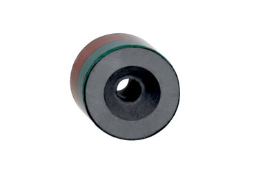
Foto van het product (individuele catalogusfoto)
Maatschets basistoestel
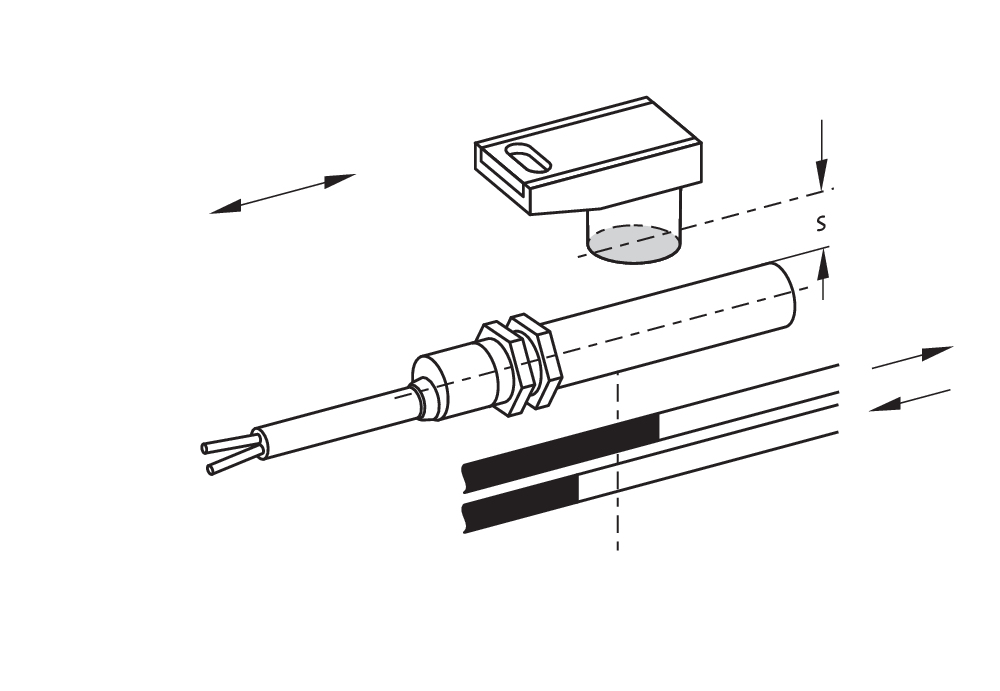
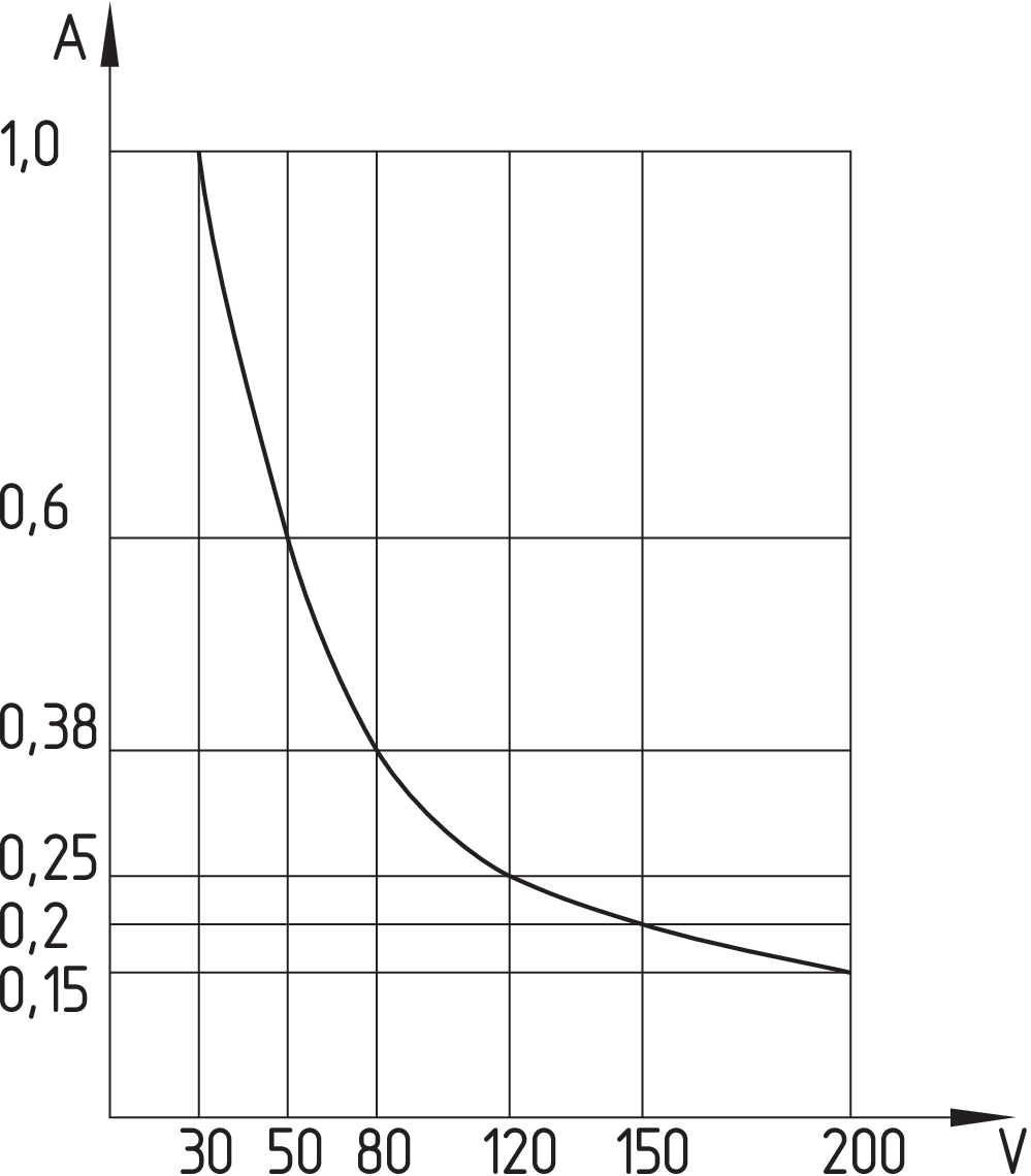
Schakelwegdiagram
Schakelwegdiagram

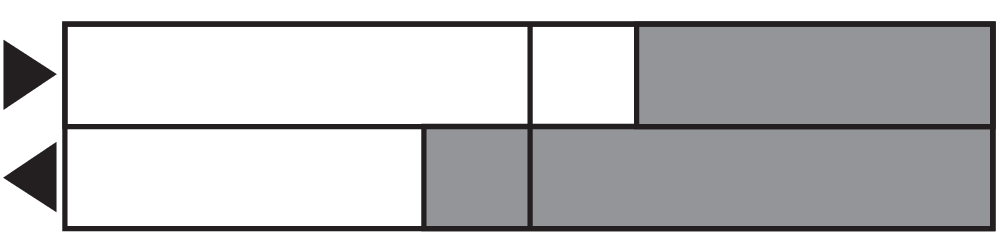
Contactschema
Contactschema
Karakteristiek diagram
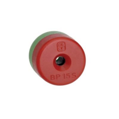
101060163 BP 15
- thermoplastic enclosure
- N-pole marked green
- S-pole marked red
- Suitable for mounting on ferrous material with a distance of 18 mm
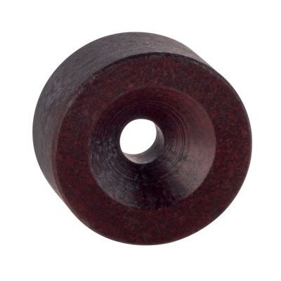
101060165 BP 15/2
- Unenclosed
- Polarity stamped in
- Suitable for mounting on ferrous material with a distance of 18 mm
101057531 BP 10
- Unenclosed
- Colour coding of poles by lables
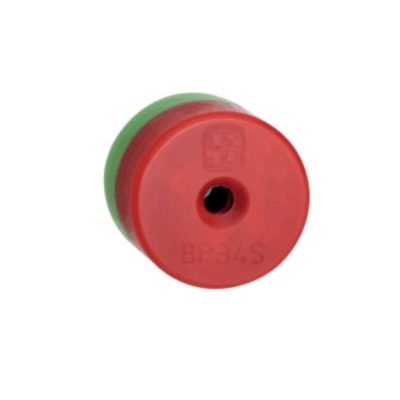
101057553 BP 34
- thermoplastic enclosure
- S-pole marked red
- N-pole marked green
- Suitable for mounting on ferrous material with a distance of 25 mm
Schmersal India Pvt. Ltd., Plot No - G-7/1, Ranjangaon MIDC, Tal. - Shirur, Dist.- Pune 412 220
De genoemde gegevens en informatie zijn zorgvuldig gecontroleerd. Afbeeldingen kunnen afwijken van het origineel. Verdere technische gegevens zijn te vinden in de handleiding. Technische wijzigingen en fouten voorbehouden.
Gegenereerd op 28-04-2025 08:35
