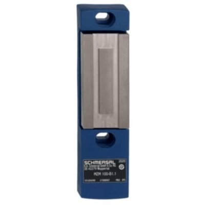
MZM 100 ST-1P2PWR100-A-DU
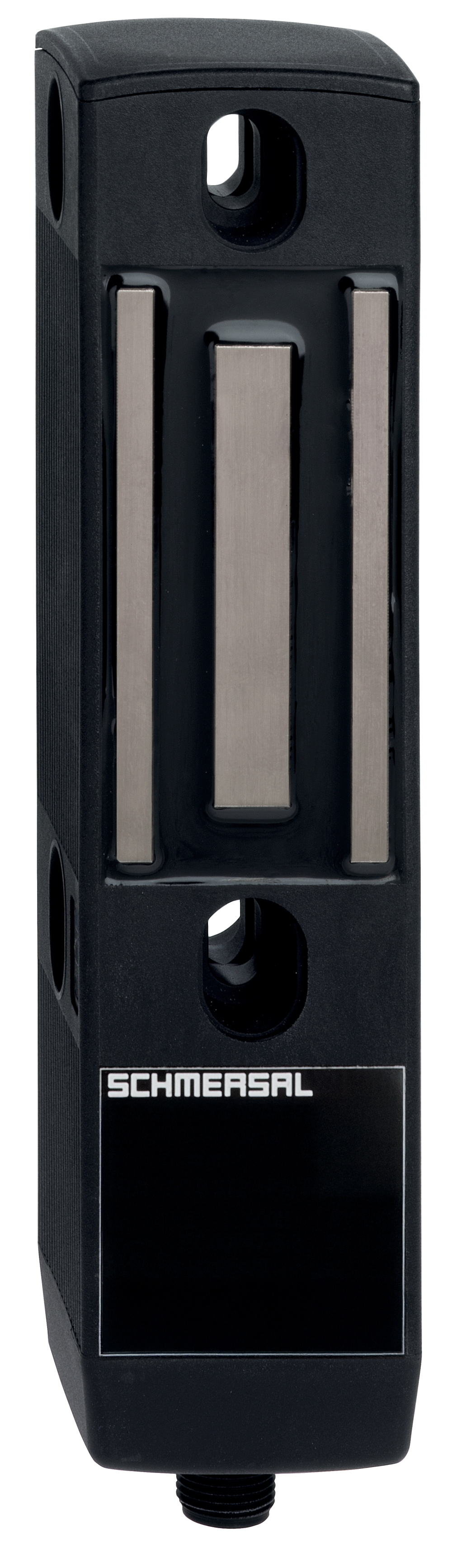
MZM 100 ST-1P2PWR100-A-DU
- Guard locking monitored
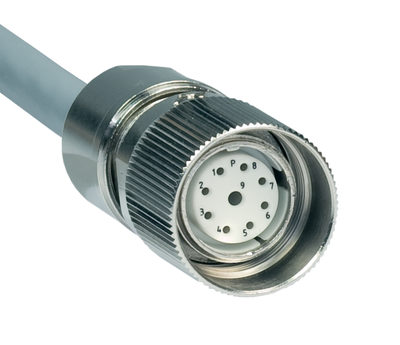
- Connector M23, 8+1-pole
- Power to lock
- Automatic latching
- Solenoid interlocks with innovating and unique operating principle
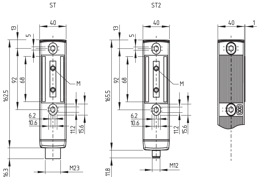
- 40 mm x 179 mm x 40 mm
- Electronic contact-free, coded system
- Thermoplastic enclosure
- Max. length of the sensor chain 200 m
- 3 LEDs to show operating conditions
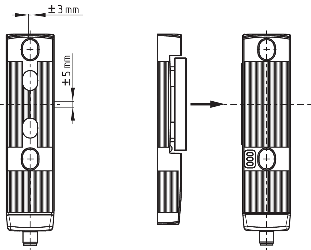
- Sensor technology permits an offset between actuator and interlock of ± 5 mm vertically and ± 3 mm horizontally
- Intelligent diagnosis
- Self-monitoring series-wiring
- Patented
Ordering data
| Note (Delivery capacity) |
Plus disponible! |
| Product type description |
MZM 100 ST-1P2PWR100-A-DU |
| Article number (order number) |
103047169 |
| EAN (European Article Number) |
4030661616377 |
| eCl@ss number, version 12.0 |
27-27-26-03 |
| eCl@ss number, version 11.0 |
27-27-26-03 |
| eCl@ss number, version 9.0 |
27-27-26-03 |
| ETIM number, version 7.0 |
EC002593 |
| ETIM number, version 6.0 |
EC002593 |
Approvals - Standards
| Certificates |
TÜV cULus UKCA |
General data
| Standards |
EN ISO 13849-1 EN ISO 14119 EN IEC 60947-5-3 EN IEC 61508 |
| Coding |
Codage universel |
| Coding level according to EN ISO 14119 |
faible |
| Working principle |
inductif |
| Housing material |
Plastique, thermoplastique renforcé de fibres de verre, auto-extinguible |
| Reaction time, maximum |
150 ms |
| Duration of risk, maximum |
150 ms |
| Gross weight |
637 g |
General data - Features
| Power to lock |
Oui |
| Solenoid interlock monitored |
Oui |
| Latching |
Oui |
| Short circuit detection |
Oui |
| Cross-circuit detection |
Oui |
| Series-wiring |
Oui |
| Safety functions |
Oui |
| Integral system diagnostics, status |
Oui |
| Number of safety contacts |
2 |
| Safety classification |
| Vorschriften |
EN ISO 13849-1 EN IEC 61508 |
Safety classification - Interlocking function
| Performance Level, up to |
e |
| Category |
4 |
| PFH value |
3,54 x 10⁻⁹ /h |
| Safety Integrity Level (SIL), suitable for applications in |
3 |
| Mission time |
20 Year(s) |
Mechanical data
| Mechanical life, minimum |
1.000.000 Operations |
| Note (Mechanical life) |
Vitesse d'attaque ≤ 0,5 m/s Manœuvres pour les protecteurs ≤ 5 kg |
| Holding force, typically |
750 N |
| Holding force, guaranteed |
500 N |
| Latching force |
100 N |
| Type of the fixing screws |
2x M6 |
| Tightening torque of the fixing screws |
8 Nm |
Mechanical data - Switching distances
| Assured switching distance "ON" Sao |
0 mm |
| Assured switching distance "OFF" Sar |
1 mm |
| Note (switching distance) |
All switching distances in accordance EN IEC 60947-5-3 |
Mechanical data - Connection technique
| Length of sensor chain, maximum |
200 m |
| Note (length of the sensor chain) |
Cable length and cross-section change the voltage drop dependiing on the output current |
| Note (series-wiring) |
Unlimited number of devices, oberserve external line fusing, max. 31 devices in case of serial diagnostic SD |
| Termination |
Connecteur M23, 8+1-pôles |
Mechanical data - Dimensions
| Length of sensor |
40 mm |
| Width of sensor |
40 mm |
| Height of sensor |
179 mm |
Ambient conditions
| Degree of protection |
IP65 IP67 |
| Ambient temperature |
-25 ... +55 °C |
| Storage and transport temperature |
-25 ... +70 °C |
| Relative humidity, minimum |
30 % |
| Relative humidity, maximum |
95 % |
| Note (Relative humidity) |
sans condensation non givrant |
| Resistance to vibrations |
10 … 150 Hz, amplitude 0,35 mm / 5 g |
| Restistance to shock |
30 g / 11 ms |
| Protection class |
III |
| Permissible installation altitude above sea level, maximum |
2.000 m |
Ambient conditions - Insulation values
| Rated insulation voltage Ui |
32 VDC |
| Rated impulse withstand voltage Uimp |
0,8 kV |
| Overvoltage category |
III |
| Degree of pollution |
3 |
Electrical data
| Operating voltage |
24 VDC -15 % / +10 % |
| No-load supply current I0, typical |
100 mA |
| Current consumption with magnet ON, average |
350 mA |
| Current consumption with magnet ON, peak |
550 mA / 10 ms |
| Rated operating voltage |
24 VDC |
| Operating current |
1.100 mA |
| Required rated short-circuit current |
100 A |
| External wire and device fuse rating |
2 A gG |
| Time to readiness, maximum |
4.000 ms |
| Switching frequency, maximum |
1 Hz |
Electrical data - Magnet control
| Designation, Magnet control |
IN |
| Switching thresholds |
-3 V … 5 V (Low) 15 V … 30 V (High) |
| Current consumption at 24 V |
10 mA |
| Magnet switch-on time |
100 % |
| Test pulse duration, maximum |
5 ms |
| Test pulse interval, minimum |
40 ms |
| Classification ZVEI CB24I, Sink |
C0 |
| Classification ZVEI CB24I, Source |
C1 C2 C3 |
Electrical data - Safety digital inputs
| Designation, Safety inputs |
X1 and X2 |
| Switching thresholds |
−3 V … 5 V (Low) 15 V … 30 V (High) |
| Current consumption at 24 V |
5 mA |
| Test pulse duration, maximum |
1 ms |
| Test pulse interval, minimum |
100 ms |
| Classification ZVEI CB24I, Sink |
C1 |
| Classification ZVEI CB24I, Source |
C1 C2 C3 |
Electrical data - Safety digital outputs
| Designation, Safety outputs |
Y1 et Y2 |
| Rated operating current (safety outputs) |
250 mA |
| Design of control elements |
protégé contre les courts-circuits, commutation P |
| Voltage drop Ud, maximum |
1 V |
| Leakage current Ir, maximum |
0,5 mA |
| Voltage, Utilisation category DC-13 |
24 VDC |
| Current, Utilisation category DC-13 |
0,25 A |
| Test pulse interval, typical |
1000 ms |
| Test pulse duration, maximum |
1 ms |
| Classification ZVEI CB24I, Source |
C1 |
| Classification ZVEI CB24I, Sink |
C1 |
Electrical data - Diagnostic outputs
| Designation, Diagnostic outputs |
OUT |
| Design of control elements |
protégé contre les courts-circuits, commutation P |
| Voltage drop Ud, maximum |
2 V |
| Voltage, Utilisation category DC-13 |
24 VDC |
| Current, Utilisation category DC-13 |
0,05 A |
Status indication
| Note (LED switching conditions display) |
Etat de fonctionnement: LED jaune Erreur défaut fonctionnel: LED rouge Tension d'alimentation UB: LED verte |
Pin assignment
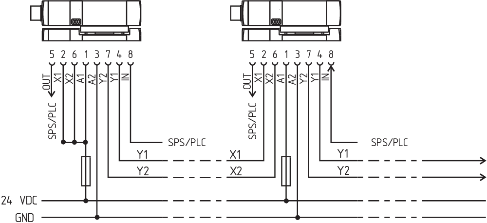
| PIN 1 |
A1 Tension d'alimentation UB |
| PIN 2 |
X1 Entrée de sécurité 1 |
| PIN 3 |
A2 GND |
| PIN 4 |
Y1 Sortie de sécurité 1 |
| PIN 5 |
OUT Sortie diagnostic "OUT" |
| PIN 6 |
X2 Entrée de sécurité 2 |
| PIN 7 |
Y2 Sortie de sécurité 2 |
| PIN 8 |
IN Electro-aimant |
| PIN 9 |
sans fonction |
Scope of delivery
| Scope of delivery |
Actuator must be ordered separately. |
Accessory
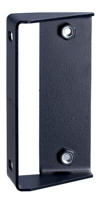
| Recommendation (actuator) |
MZM 100-B1.1 |
Note
| Note (General) |
As long as the actuating unit is applied to the solenoid interlock, the unlocked safety guard can be relocked. In this case, the safety outputs are re-enabled, so that the safety guard must not be opened. |
Filtre de langue
Fiches techniques
Mode d'emploi et déclaration de conformité
Mode d'emploi (annexe/guide raccourci)
Certificat UL
Certificat UKCA
Homologation TÜV
Bibliothèque/Library SISTEMA-VDMA
Télécharger la dernière version d'Adobe Reader
Photo du produit (photo individuelle de catalogue)
Plan d'encombrement composant de base
Plan d'encombrement divers
Type de contact

Exemple de câblage
101204290 MZM 100-B1.1
- actuator free from play
- neutralisation of undesired noises
101210642 MZM 100 TARGET
- for the variable setting of the latching force
- gradually adjustable by steps of approx. 10 N within a range from approx. 30 N to 100 N
101209958 A-K8+1P-M23-S-G-10M-BK-1-X-X-4
- Pre-wired cable
- 8+1-pole
101209959 A-K8+1P-M23-S-G-5M-BK-1-X-X-4
- Pre-wired cable
- 8+1-pole

101209970 S-K8+1P-M23-S-G-X-X-X-X-X-4 (SOLDER)
- Soldering terminal
101209994 S-K8+1P-M23-S-G-X-X-X-X-X-4 (CRIMP)
- with shrink connection

103009970 SRB-E-201LC
- Plug-in screw terminals with coding
- STOP 0 Function
- 1 oder 2-channel control
- Start button / Auto-start
- 2 Safety outputs 2 A
- 1 Signalling output

103007672 SRB-E-301ST
- Plug-in screw terminals with coding
- STOP 0 Function
- 1 oder 2-channel control
- Start button / Auto-start
- 1 Auxiliary contact
- 3 safety contacts

103009973 SRB-E-204ST
- Plug-in screw terminals with coding
- STOP 0 Function
- Monitoring of 4 sensors
- Start button / Auto-start
- 2 Safety outputs
- 4 Signalling outputs
101211066 MZM 100 ST2-1P2PWRE-A
- Guard locking monitored
- Connector M12, 8-pole
- Power to lock
- Automatic latching
- Solenoid interlocks with innovating and unique operating principle
- 40 mm x 179 mm x 40 mm
- Electronic contact-free, coded system
- Thermoplastic enclosure
- Max. length of the sensor chain 200 m
- 3 LEDs to show operating conditions
- Sensor technology permits an offset between actuator and interlock of ± 5 mm vertically and ± 3 mm horizontally
- Intelligent diagnosis
- Self-monitoring series-wiring
- Patented
| UK Declaration of Conformity |  |
| Company: | K.A. Schmersal GmbH & Co. KG Möddinghofe 30 42279 Wuppertal Germany Internet: www.schmersal.com |
| Declaration: | We hereby, under sole responsibility, certify that the hereafter described components both in their basic design and construction conform to the relevant statutory requirements, regulations and designated standards of the United Kingdom. |
| Name of the component: | MZM 100 MZM 100 B |
| Type: | See ordering code |
| Description of the component: | Interlocking device with electromagnetic interlock for safety functions (MZM 100) and safety switch with interlocking functions (MZM 100 B) |
| Relevant legislation: | Supply of Machinery (Safety) Regulations | 2008 |
| Electromagnetic Compatibility Regulations | 2016 | |
| The Restriction of the Use of Certain Hazardous Substances in Electrical and Electronic Equipment Regulations | 2012 |
| Designated standards: | EN 60947-5-3:2013 EN ISO 14119:2013 EN ISO 13849-1:2015 IEC 61508 parts 1-7:2010 |
| Approved body for Type Examination: | TÜV Rheinland UK Ltd. 1011 Stratford Road Solihull, B90 4BN ID: 2571 |
| Type examination certificate: | 01/205U/5778.00/23 |
| UK-Importer / Person authorised for the compilation of the technical documentation: | Schmersal UK Ltd. Paul Kenney Unit 1, Sparrowhawk Close Enigma Business Park Malvern, Worcestershire, WR14 1GL |
| Place and date of issue: | Wuppertal, April 18, 2023 |
 |
| Authorised signature Philip Schmersal Managing Director |
| Déclaration UE de conformité | |
| Original | K.A. Schmersal GmbH & Co. KG Möddinghofe 30 42279 Wuppertal Germany Internet: www.schmersal.com |
| Déclaration: | Par la présente, nous certifions que les composants identifiés ci-après répondent de par leur conception et leur construction aux exigences des Directives Européennes applicables. |
| Désignation du composant: | MZM 100 MZM 100 B |
| Type: | voir exemple de commande |
| Description du composant: | Interverrouillage électromagnétique pour fonctions de sécurité (MZM 100) ou interrupteur de sécurité avec fonction de verrouillage (MZM 100 B) |
| Directives pertinentes: | Directive Machines | 2006/42/CE |
| Directive CEM | 2014/30/EU | |
| Directive RoHS | 2011/65/EU |
| Normes appliquées: | EN 60947-5-3:2013 EN ISO 14119:2013 EN ISO 13849-1:2015 IEC 61508 parties 1-7:2010 |
| Organisme notifié pour l' examen de type: | TÜV Rheinland Industrie Service GmbH Am Grauen Stein, 51105 Köln N° d'ident.: 0035 |
| Certificat d'examen CE de type: | 01/205/5778.00/20 |
| Représentant autorisé à préparer et composer la documentation technique: | Oliver Wacker Möddinghofe 30 42279 Wuppertal |
| Lieu et date de l'émission: | Wuppertal, le 18 novembre 2020 |
|
| Signature à l'effet d'engager la société Philip Schmersal Président Directeur Général |
Schmersal India Pvt. Ltd., Plot No - G-7/1, Ranjangaon MIDC, Tal. - Shirur, Dist.- Pune 412 220
Les données et les valeurs ont été soigneusement vérifiées. Les illustrations peuvent être différentes de l'original. Vous trouverez d'avantage de caractéristiques techniques dans les manuels d’instructions. Sous réserve de modifications techniques et errata.
Généré le: 06/08/2025 03:29