SRB206ST-230V
SRB206ST-230V
Downloads
- 2 safety contacts, STOP 0
- 6 Signalling outputs
- Multi-evaluation of up to 6 safety guards
- Suitable for the signal processing of outputs with contact sensors
Ordering data
| Note (Delivery capacity) |
Nicht mehr lieferbar! |
| Replacement article number |
101177164 |
| Product type description |
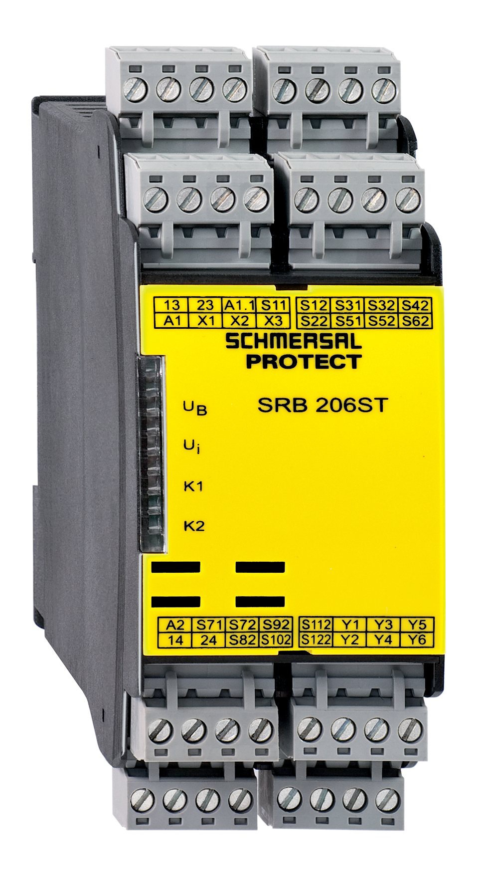
SRB206ST-230V |
| Article number (order number) |
101174014 |
| EAN (European Article Number) |
4250116201860 |
| eCl@ss number, version 12.0 |
27-37-18-19 |
| eCl@ss number, version 11.0 |
27-37-18-19 |
| eCl@ss number, version 9.0 |
27-37-18-19 |
| ETIM number, version 7.0 |
EC001449 |
| ETIM number, version 6.0 |
EC001449 |
Approvals - Standards
| Certificates |
cULus |
General data
| Standards |
EN IEC 62061 EN ISO 13849-1 EN IEC 60947-5-1 EN IEC 60947-5-3 EN IEC 60947-5-5 EN IEC 61508 EN IEC 60204-1 EN IEC 60947-1 |
| Climatic stress |
EN 60068-2-78 |
| Housing material |
Kunststoff, glasfaserverstärkter Thermoplast, belüftet |
| Gross weight |
320 g |
General data - Features
| Electronic Fuse |
Ja |
| Wire breakage detection |
Ja |
| Removable Terminals |
Ja |
| Start input |
Ja |
| Feedback circuit |
Ja |
| Automatic reset function |
Ja |
| Reset edge detection |
Ja |
| Earth connection detection |
Ja |
| Integral system diagnostics, status |
Ja |
| Number of auxiliary contacts |
6 |
| Number of LEDs |
4 |
| Number of normally closed (NC) |
12 |
| Number of safety contacts |
2 |
| Number of signalling outputs |
6 |
| Safety classification |
| Vorschriften |
EN IEC 60947-5-1 EN IEC 61508 |
| Stop-Category |
0 |
| Safety classification - Relay outputs |
| Performance Level, stop 0, up to |
d |
| Category, Stop 0 |
3 |
| Diagnostic Coverage (DC) Level, Stop 0 |
> 60 % |
| PFH value, Stop 0 |
2,00 x 10⁻⁷ /h |
| Safety Integrity Level (SIL), Stop 0, suitable for applications in |
3 |
| Mission time |
20 Year(s) |
| Common Cause Failure (CCF), minimum |
65 |
Mechanical data
| Mechanical life, minimum |
10.000.000 Operations |
| Mounting |
Schnellbefestigung für Normschiene nach DIN EN 60715 |
Mechanical data - Connection technique
| Terminal designations |
IEC/EN 60947-1 |
| Termination |
starr oder flexibel Schraubanschluss M20 x 1.5 |
| Cable section, minimum |
0,25 mm² |
| Cable section, maximum |
2,5 mm² |
| Tightening torque of Clips |
0,6 Nm |
Mechanical data - Dimensions
| Width |
45 mm |
| Height |
100 mm |
| Depth |
121 mm |
Ambient conditions
| Degree of protection of the enclosure |
IP40 |
| Degree of protection of the mounting space |
IP54 |
| Degree of protection of clips or terminals |
IP20 |
| Ambient temperature |
-25 ... +45 °C |
| Storage and transport temperature |
-40 ... +85 °C |
| Resistance to vibrations |
10 ... 55 Hz, Amplitude 0,35 mm, ± 15 % |
| Restistance to shock |
30 g / 11 ms |
Ambient conditions - Insulation values
| Rated impulse withstand voltage Uimp |
4 kV |
| Overvoltage category |
III |
| Degree of pollution |
2 |
Electrical data
| Frequency range |
50 Hz 60 Hz |
| Type of voltage range |
AC |
| Rated operating voltage |
48 ... 240 VAC |
| Operating current |
275 mA |
| Rated AC voltage for controls, 50 Hz, minimum |
48 VAC |
| Rated control voltage at AC 50 Hz, maximum |
240 VAC |
| Rated AC voltage for controls, 60 Hz, minimum |
48 VAC |
| Rated control voltage at AC 60 Hz, maximum |
240 VAC |
| Utilisation category AC-15 |
230 VAC |
| Utilisation category AC-15 |
6 A |
| Utilisation category DC-13 |
24 VDC |
| Utilisation category DC-13 |
6 A |
| Electrical power consumption |
6,8 W |
| Contact resistance, maximum |
0,1 Ω |
| Note (Contact resistance) |
in Neuzustand |
| Drop-out delay in case of "emergency stop", maximum |
30 ms |
| Pull-in delay at RESET, typically |
50 ms |
| Material of the contacts, electrical |
AgCdO, selbstreinigend, zwangsgeführt |
Electrical data - Digital inputs
| Conduction resistance, maximum |
40 Ω |
Electrical data - Electromagnetic compatibility (EMC)
| EMC rating |
EMV-Richtlinie |
Status indication
| Indicated operating states |
Stellung der Relais K2 Stellung der Relais K1 Interne Betriebsspannung Ui |
Other data
| Note (applications) |
Schutzeinrichtung NOT-HALT-Taster Seilzug-Notschalter |
Note
| Note (General) |
Induktive Verbraucher (Schütze, Relais etc.) sind durch eine geeignete Beschaltung zu entstören. |
Wiring example
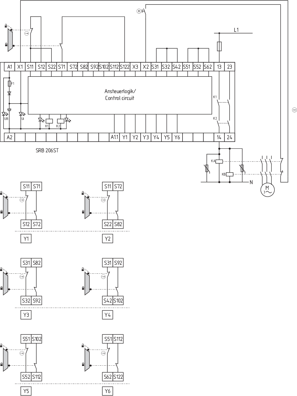
| Note (Wiring diagram) |
Das Schaltungsbeispiel ist bei geschlossenen Schutzeinrichtungen und im spannungslosen Zustand dargestellt. Automatischer Start: Die Programmierung auf automatischen Start erfolgt durch die Einbindung des Rückführkreises an die Klemmen X1/X3. Bei nicht benötigtem Rückführkreis ist dieser durch eine Brücke zu ersetzen. Eingangsebene: 2-kanalige Ansteuerung, dargestellt am Beispiel einer Schutztürüberwachung mit zwei Positionsschaltern, davon einer zwangsöffnend, externem Reset-Taster (R) und Rückführkreis (H2). Die Ansteuerung erkennt Drahtbrüche und Erdschlüsse im Überwachungskreis. Leistungsebene: 2-kanalige Ansteuerung geeignet zur Kontaktverstärkung bzw. Kontaktvervielfältigung durch Schütze oder Relais mit zwangsgeführten Kontakten. Werden mehr Schutztüren überwacht, sind diese gemäß der Anschlusstabelle anzuschließen. Ein einzelner Fehler bei den Sensoren führt nicht zum Verlust der Sicherheit. Wenn der einzelne Fehler auftritt, bleibt die Sicherheitsfunktion immer erhalten. Einige, aber nicht alle Fehler werden erkannt. Eine Anhäufung unerkannter Fehler kann zum Verlust der Sicherheitsfunktion führen. |
Sprachfilter
Datenblatt
Betriebsanleitung und Konformitätserklärung
UL-Zertifikat
Schaltungsbeispiel (elektr. Verdrahtung)
Kraftwegdiagramm
Download der aktuellen Version von Adobe Reader
Produktbild (Katalogeinzelphoto )
Schaltungsbeispiel
Symbol (technischer Standard)

Schmersal India Pvt. Ltd., Plot No - G-7/1, Ranjangaon MIDC, Tal. - Shirur, Dist.- Pune 412 220
Die genannten Daten und Angaben wurden sorgfältig geprüft. Abbildungen können vom Original abweichen. Weitere technische Daten finden Sie in der Betriebsanleitung. Technische Änderungen und Irrtümer vorbehalten.
Generiert am: 22.03.2025, 08:58