SRB219IT-24VAC/DC
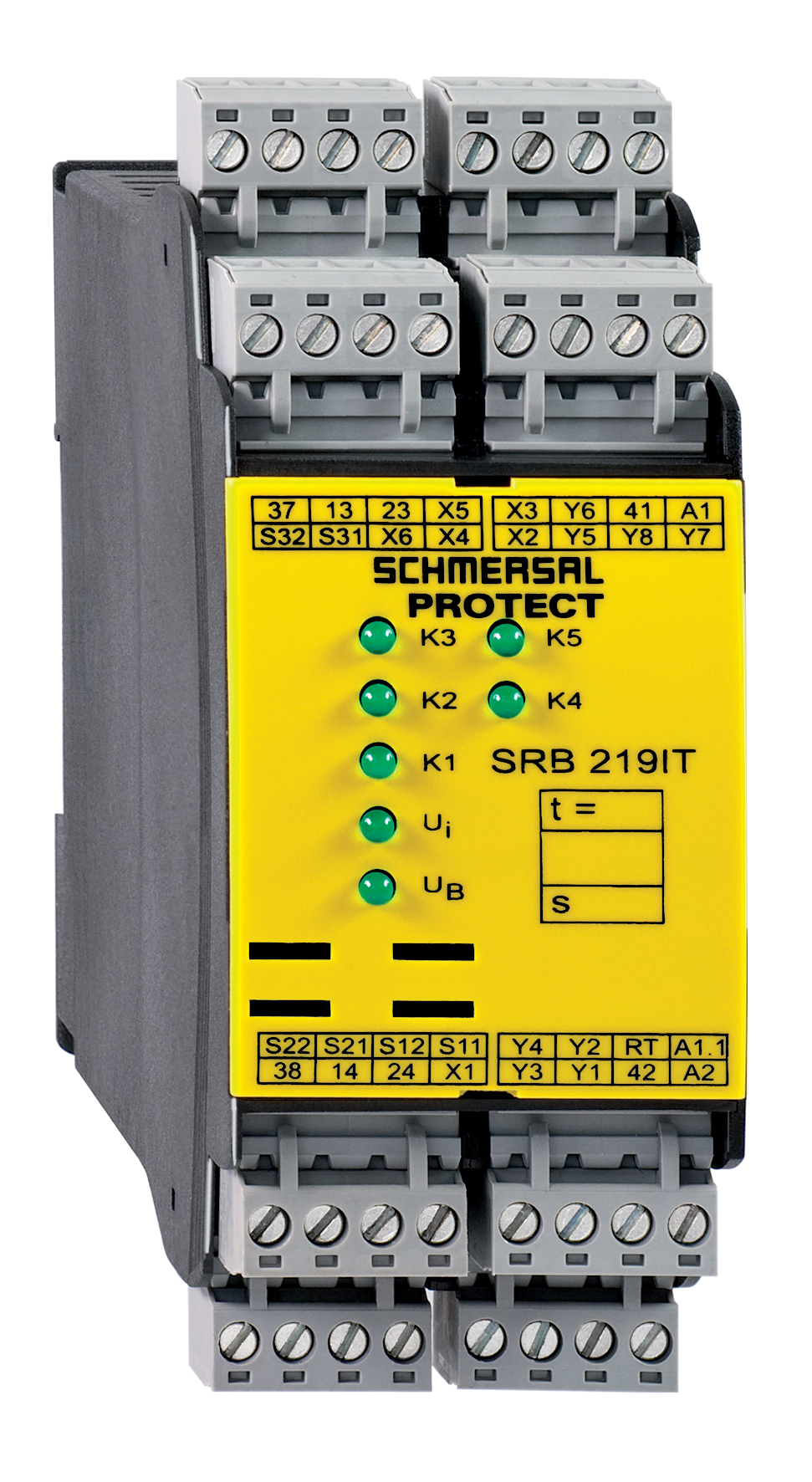
SRB219IT-24VAC/DC
Downloads
- Multifunctional safety relay module for superior diagnostics and visualisation
- Suitable for the signal processing of outputs with contact sensors
- Suitable for the signal processing of outputs with contact sensors
- Suitable for signal processing of outputs connected to potentials (AOPDs), e.g. safety light grids/curtains
- 1 + 8 Signalling outputs
- 2 safety contacts, STOP 0;
1 safety contact, STOP 1 (adjustable 1 … 30 s)
Ordering data
| Note (Delivery capacity) |
Nicht mehr lieferbar! |
| Replacement article number |
101159512 |
| Product type description |
SRB219IT-24VAC/DC |
| Article number (order number) |
101158208 |
| EAN (European Article Number) |
4250116201570 |
| eCl@ss number, version 12.0 |
27-37-18-19 |
| eCl@ss number, version 11.0 |
27-37-18-19 |
| eCl@ss number, version 9.0 |
27-37-18-19 |
| ETIM number, version 7.0 |
EC001449 |
| ETIM number, version 6.0 |
EC001449 |
Approvals - Standards
| Certificates |
cULus |
General data
| Standards |
EN IEC 62061 EN ISO 13849-1 EN IEC 60947-5-1 EN IEC 60947-5-3 EN IEC 60947-5-5 EN IEC 61508 EN IEC 60204-1 EN IEC 60947-1 |
| Climatic stress |
EN 60068-2-78 |
| Housing material |
Kunststoff, glasfaserverstärkter Thermoplast, belüftet |
| Gross weight |
360 g |
General data - Features
| Electronic Fuse |
Ja |
| Wire breakage detection |
Ja |
| Cross-circuit detection |
Ja |
| Removable Terminals |
Ja |
| Start input |
Ja |
| Feedback circuit |
Ja |
| Automatic reset function |
Ja |
| Reset edge detection |
Ja |
| Earth connection detection |
Ja |
| Integral system diagnostics, status |
Ja |
| Number of auxiliary contacts |
1 |
| Number of LEDs |
7 |
| Number of normally closed (NC) |
2 |
| Number of undelayed semi-conductor outputs with signaling function |
7 |
| Number of delayed semi-conductor outputs with signaling function. |
1 |
| Number of safety contacts |
3 |
| Number of signalling outputs |
8 |
| Safety classification |
| Vorschriften |
EN IEC 60947-5-1 EN IEC 61508 |
| Stop-Category |
0 1 |
| Safety classification - Relay outputs |
| Performance Level, stop 0, up to |
e |
| Performance Level, stop 1, up to |
d |
| Category, Stop 0 |
4 |
| Category, Stop 1 |
3 |
| Diagnostic Coverage (DC) Level, Stop 0 |
≥ 99 % |
| Diagnostic Coverage (DC) Level, Stop 1 |
> 60 |
| PFH value, Stop 0 |
2,00 x 10⁻⁸ /h |
| PFH value, Stop 1 |
2,00 x 10⁻⁷ /h |
| Safety Integrity Level (SIL), Stop 0, suitable for applications in |
3 |
| Safety Integrity Level (SIL), Stop 1, suitable for applications in |
2 |
| Mission time |
20 Year(s) |
| Common Cause Failure (CCF), minimum |
65 |
Mechanical data
| Mechanical life, minimum |
10.000.000 Operations |
| Mounting |
Schnellbefestigung für Normschiene nach DIN EN 60715 |
Mechanical data - Connection technique
| Terminal designations |
IEC/EN 60947-1 |
| Termination |
starr oder flexibel Schraubanschluss M20 x 1.5 |
| Cable section, minimum |
0,25 mm² |
| Cable section, maximum |
2,5 mm² |
| Tightening torque of Clips |
0,6 Nm |
Mechanical data - Dimensions
| Width |
45 mm |
| Height |
100 mm |
| Depth |
121 mm |
Ambient conditions
| Degree of protection of the enclosure |
IP40 |
| Degree of protection of the mounting space |
IP54 |
| Degree of protection of clips or terminals |
IP20 |
| Ambient temperature |
-25 ... +45 °C |
| Storage and transport temperature |
-40 ... +85 °C |
| Resistance to vibrations |
10 ... 55 Hz, Amplitude 0,35 mm, ± 15 % |
| Restistance to shock |
30 g / 11 ms |
Ambient conditions - Insulation values
| Rated impulse withstand voltage Uimp |
4 kV |
| Overvoltage category |
III |
| Degree of pollution |
2 |
Electrical data
| Frequency range |
50 Hz 60 Hz |
| Operating voltage |
24 VAC -15 % / +10 % |
| Ripple voltage |
10 % |
| Rated operating voltage |
24 VAC |
| Rated operating voltage |
24 VDC |
| Operating current |
200 mA |
| Rated AC voltage for controls, 50 Hz, minimum |
20,4 VAC |
| Rated control voltage at AC 50 Hz, maximum |
26,4 VAC |
| Rated AC voltage for controls, 60 Hz, minimum |
20,4 VAC |
| Rated control voltage at AC 60 Hz, maximum |
26,4 VAC |
| Rated AC voltage for controls at DC minimum |
20,4 VDC |
| Rated control voltage at DC, maximum |
28,8 VDC |
| Electrical power consumption |
4,4 W |
| Electrical power consumption |
5,2 VA |
| Contact resistance, maximum |
0,1 Ω |
| Note (Contact resistance) |
in Neuzustand |
| Drop-out delay in case of "emergency stop", maximum |
15 ms |
| Pull-in delay at automatic start, maximum, typically |
60 ms |
| Pull-in delay at RESET, typically |
200 ms |
| Material of the contacts, electrical |
AgSnO, selbstreinigend, zwangsgeführt |
Electrical data - Digital inputs
| Conduction resistance, maximum |
40 Ω |
Electrical data - Electromagnetic compatibility (EMC)
| EMC rating |
EMV-Richtlinie |
Status indication
| Indicated operating states |
Stellung der Relais K2 Stellung der Relais K1 Interne Betriebsspannung Ui Stellung der Relais K3 Stellung der Relais K5 |
Other data
| Note (applications) |
Sicherheits-Sensor Schutzeinrichtung NOT-HALT-Taster Seilzug-Notschalter Sicherheits-Lichtvorhang |
Note
| Note (General) |
Induktive Verbraucher (Schütze, Relais etc.) sind durch eine geeignete Beschaltung zu entstören. |
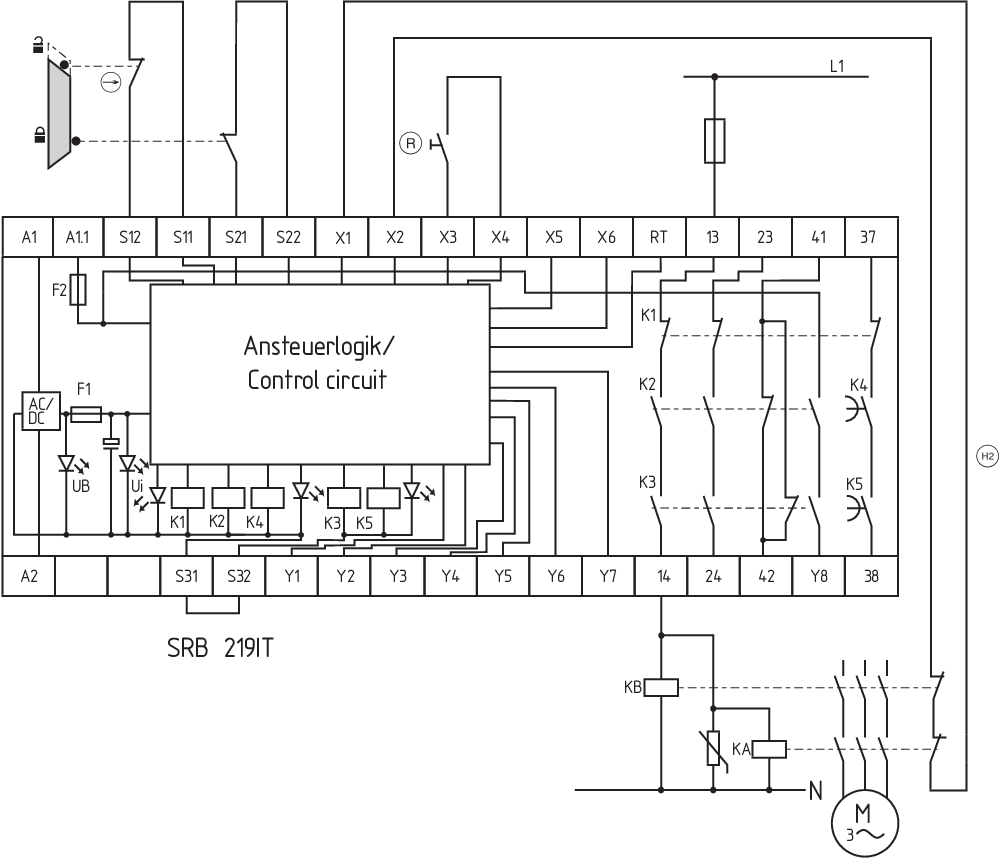
Wiring example
| Note (Wiring diagram) |
Das Schaltungsbeispiel ist bei geschlossenen Schutzeinrichtungen und im spannungslosen Zustand dargestellt. Die ISD-Tabellen (Integrierte System-Diagnose) zur Analyse der Fehlermeldungen und ihrer Ursachen sind im Anhang aufgeführt. Die Ansteuerung erkennt Drahtbrüche und Erdschlüsse im Überwachungskreis. Leistungsebene: 2-kanalige Ansteuerung geeignet zur Kontaktverstärkung bzw. Kontaktvervielfältigung durch Schütze oder Relais mit zwangsgeführten Kontakten. Potenzialbehaftete Ausgänge von Lichtgittern/-vorhängen (p-schaltend) an S12/S22 anschließen. Die Geräte müssen auf gleichem Bezugspotenzial liegen. Zeitverzögerung: Die zeitverzögerte Sicherheitsfreigabe 37/38 ist von 1 bis 30 Sekunden abfallverzögert einstellbar (siehe Einstellanweisung). Die Einstellung der Abfallverzögerungszeit erfolgt durch ein Potentiometer unter dem Deckel der Gehäusefront. Bei 2-kanalige Ansteuerung mit Querschlusserkennung die Öffnerkontakte S11/S12 und S31/S32 anschließen und S21/S22 brücken Startfunktion / Reset-Taster: Die Programmierung der Funktion" Abfallende Flanke" erfolgt durch den Schalter "AF" unter dem Gehäusedeckel (Schalterstellung = 1). Die Programmierung auf automatischen Start erfolgt durch Brücken der Klemmen X3/X5 und Schalten des Schalters "AF" auf 0. Der Zeitversatz zwischen den Kanälen beträgt ca. 100 ms. Die Programmierung auf unendlichen Zeitversatz zwischen den Kanälen 1 und 2 erfolgt durch Brücken der Klemmen X3/X6. Eingangsebene: 2-kanalige Ansteuerung, dargestellt am Beispiel einer Schutztürüberwachung mit zwei Positionsschaltern, davon einer zwangsöffnend, externem Reset-Taster (R) und Rückführkreis (H2). (Beispiel ohne Querschlusserkennung) Bei 1-kanaliger Ansteuerung den Öffnerkontakt S11/S12 anschließen und S21/S22 + S31/S32 brücken Vorzeitige Abschaltung der Zeitverzögerung: Über den Eingang RT kann die Abfallverzögerungszeit vorzeitig beendet werden. Der Eingang RT ermöglicht die zeitverzögerte Freigabe 37/38 vor Ablauf der eingestellten Zeit „abzuschalten”. F1 = Hybridsicherung F2 = Absicherung Meldeausgänge |
Sprachfilter
Datenblatt
Betriebsanleitung und Konformitätserklärung
UL-Zertifikat
Schaltungsbeispiel (elektr. Verdrahtung)
Kraftwegdiagramm
Download der aktuellen Version von Adobe Reader
Produktbild (Katalogeinzelphoto )
Schaltungsbeispiel
Symbol (technischer Standard)

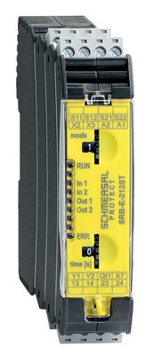
103007222 SRB-E-212ST
- Plug-in screw terminals with coding
- STOP 0 / 1 Function
- 1 oder 2-channel control
- 2 safety contacts STOP 0
- 1 Safety output STOP 1
- Drop-out delay 0 … 30
Schmersal India Pvt. Ltd., Plot No - G-7/1, Ranjangaon MIDC, Tal. - Shirur, Dist.- Pune 412 220
Die genannten Daten und Angaben wurden sorgfältig geprüft. Abbildungen können vom Original abweichen. Weitere technische Daten finden Sie in der Betriebsanleitung. Technische Änderungen und Irrtümer vorbehalten.
Generiert am: 28.03.2025, 09:03
