SRB302X3-24/115V
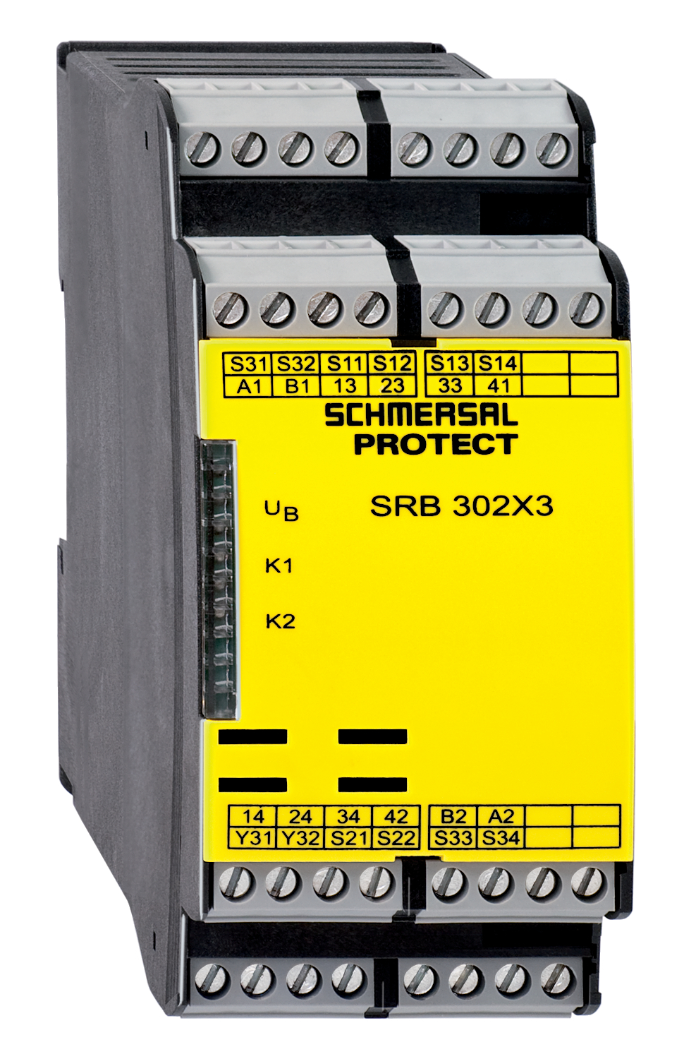
SRB302X3-24/115V
Downloads
- Suitable for the signal processing of outputs with contact sensors
- Suitable for signal processing of outputs connected to potentials (AOPDs), e.g. safety light grids/curtains
- 3 safety contacts, STOP 0
- 2 Signalling outputs
Ordering data
| Note (Delivery capacity) |
Ej tillgänglig! |
| Product type description |
SRB302X3-24/115V |
| Article number (order number) |
101183197 |
| EAN (European Article Number) |
4250116202157 |
| eCl@ss number, version 12.0 |
27-37-18-19 |
| eCl@ss number, version 11.0 |
27-37-18-19 |
| eCl@ss number, version 9.0 |
27-37-18-19 |
| ETIM number, version 7.0 |
EC001449 |
| ETIM number, version 6.0 |
EC001449 |
Approvals - Standards
| Certificates |
cULus |
General data
| Standards |
EN IEC 62061 EN ISO 13849-1 EN IEC 60947-5-1 EN IEC 60947-5-3 EN IEC 60947-5-5 EN IEC 61508 EN IEC 60204-1 EN IEC 60947-1 |
| Climatic stress |
EN 60068-2-78 |
| Housing material |
Plast, glasfiberarmerad termoplast, ventilerad |
| Gross weight |
520 g |
General data - Features
| Electronic Fuse |
Ja |
| Wire breakage detection |
Ja |
| Cross-circuit detection |
Ja |
| Start input |
Ja |
| Feedback circuit |
Ja |
| Automatic reset function |
Ja |
| Reset edge detection |
Ja |
| Earth connection detection |
Ja |
| Integral system diagnostics, status |
Ja |
| Number of auxiliary contacts |
2 |
| Number of LEDs |
3 |
| Number of normally closed (NC) |
2 |
| Number of safety contacts |
3 |
| Safety classification |
| Vorschriften |
EN IEC 60947-5-1 EN IEC 61508 |
| Stop-Category |
0 |
| Safety classification - Relay outputs |
| Performance Level, up to |
e |
| Category |
4 |
| Diagnostic Coverage (DC) Level |
> 99 % |
| PFH value |
2,00 x 10⁻⁸ /h |
| Safety Integrity Level (SIL), suitable for applications in |
3 |
| Mission time |
20 Year(s) |
| Common Cause Failure (CCF), minimum |
65 |
Mechanical data
| Mechanical life, minimum |
10 000 000 Operations |
| Mounting |
snäpps på standard-DIN-skena enligt EN 60715 |
Mechanical data - Connection technique
| Terminal designations |
IEC/EN 60947-1 |
| Termination |
styv eller flexibel Skruvkoppling M20 x 1,5 |
| Cable section, minimum |
0,25 mm² |
| Cable section, maximum |
2,5 mm² |
| Tightening torque of Clips |
0,6 Nm |
Mechanical data - Dimensions
| Width |
45 mm |
| Height |
100 mm |
| Depth |
121 mm |
Ambient conditions
| Degree of protection of the enclosure |
IP40 |
| Degree of protection of the mounting space |
IP54 |
| Degree of protection of clips or terminals |
IP20 |
| Ambient temperature |
-25 ... +60 °C |
| Storage and transport temperature |
-40 ... +85 °C |
| Resistance to vibrations |
10 ... 55 Hz, amplitud 0,35 mm |
| Restistance to shock |
30 g / 11 ms |
Ambient conditions - Insulation values
| Rated impulse withstand voltage Uimp |
4 kV |
| Overvoltage category |
III |
| Degree of pollution |
2 |
Electrical data
| Frequency range |
50 Hz 60 Hz |
| Operating voltage |
24 VDC -10 % / +20 % |
| Operating voltage |
24 ... 230 VAC -15 % / +10 % |
| Ripple voltage |
10 % |
| Type of voltage range |
AC |
| Rated operating voltage |
24 VDC |
| Rated operating voltage |
24 ... 230 VAC |
| Rated AC voltage for controls, 50 Hz, minimum |
20,4 VAC 26,4 VAC |
| Rated AC voltage for controls at DC minimum |
20,4 VDC |
| Rated control voltage at DC, maximum |
28,8 VDC |
| Utilisation category AC-15 |
230 VAC |
| Utilisation category AC-15 |
6 A |
| Utilisation category DC-13 |
24 VDC |
| Utilisation category DC-13 |
6 A |
| Electrical power consumption |
2,5 W |
| Electrical power consumption |
5 VA |
| Contact resistance, maximum |
0,1 Ω |
| Note (Contact resistance) |
i nyskick |
| Drop-out delay in case of power failure, typically |
60 ms |
| Drop-out delay in case of "emergency stop", maximum |
20 ms |
| Pull-in delay at RESET, typically |
20 ms |
| Material of the contacts, electrical |
AgSn0. självrengörande, tvångsstyrd |
Electrical data - Digital inputs
| Conduction resistance, maximum |
40 Ω |
Electrical data - Electromagnetic compatibility (EMC)
| EMC rating |
EMC-Directive |
Status indication
| Indicated operating states |
Positionsrelä K2 Positionsrelä K1 |
Other data
| Note (applications) |
Skyddsanordning Nödstoppsknapp Linnödstopp Säkerhetsljusridå |
Note
| Note (General) |
Induktiva laster (t.ex. kontaktorer, reläer etc.) måste dämpas med hjälp av en lämplig krets. |
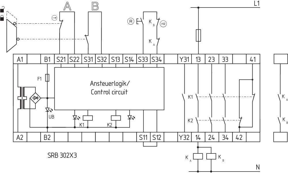
Wiring example
| Note (Wiring diagram) |
Kopplingsdiagrammet visas med skyddsdörrarna stängda och i strömlöst tillstånd. Reläutgångar: Lämpliga för 2 kanalstyrning, för utökning av antalet kontakter med hjälp av kontaktorer eller reläer med positivt styrda kontakter. Styrenheten identifierar kortslutning, kabelbrott och jordfel i övervakningskretsen. Tvåkanalig övervakning för en skyddsdörr med två brytare varav minst en kontakt har tvångsbrytning, med extern reset (R). (H2) = återkopplingskrets |
Språk filter
Datablad
Driftsinstruktion och EU-försäkran om överensstämmelse
UL-certifikat
Kopplingsexempel (elektr. trådning)
Ladda ned senaste versionen av Adobe reader
Produktbild (singelfoto i katalog)
Kopplingsexempel
Symbol (teknisk standard)


103007672 SRB-E-301ST
- Plug-in screw terminals with coding
- STOP 0 Function
- 1 oder 2-channel control
- Start button / Auto-start
- 1 Auxiliary contact
- 3 safety contacts
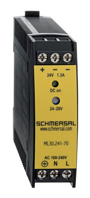
103015923 ML30.241-70
- 1-phase DIN rail power supplies
- AC 100-240V Wide-range input
- DC Output 24-28VDC / 1,3-1,1A / 30W
- Efficiency up to 89,4%
- Width only 22,5mm
Schmersal India Pvt. Ltd., Plot No - G-7/1, Ranjangaon MIDC, Tal. - Shirur, Dist.- Pune 412 220
Alla data och värden har kontrollerats noga. Bilder kan avvika från originalet. Ytterligare tekniska data finns i manualen. Tekniska ändringar och fel förbehålles.
Genererat den 2025-03-23 10:55