SRB401EM115V
SRB401EM115V
Downloads
- Expander module for contact expansion
- 4 safety contacts, STOP 0
- 1 Signalling output
Ordering data
| Note (Delivery capacity) |
Not available! |
| Replacement article number |
101195652 |
| Product type description |
SRB401EM115V |
| Article number (order number) |
101183481 |
| EAN (European Article Number) |
4250116202461 |
| eCl@ss number, version 12.0 |
27-37-18-19 |
| eCl@ss number, version 11.0 |
27-37-18-19 |
| eCl@ss number, version 9.0 |
27-37-18-19 |
| ETIM number, version 7.0 |
EC001449 |
| ETIM number, version 6.0 |
EC001449 |
General data
| Standards |
EN IEC 62061 EN ISO 13849-1 EN IEC 60947-5-1 EN IEC 60947-5-3 EN IEC 60947-5-5 EN IEC 61508 EN IEC 60204-1 EN IEC 60947-1 |
| Climatic stress |
EN 60068-2-78 |
| Housing material |
グラスファイバー強化熱可塑性樹脂、換気口付き |
| Gross weight |
260 g |
General data - Features
| Wire breakage detection |
Yes |
| Removable Terminals |
Yes |
| Feedback circuit |
Yes |
| Automatic reset function |
Yes |
| Earth connection detection |
Yes |
| Integral system diagnostics, status |
Yes |
| Number of auxiliary contacts |
1 |
| Number of LEDs |
1 |
| Number of normally closed (NC) |
1 |
| Number of safety contacts |
4 |
| Safety classification |
| Vorschriften |
EN IEC 60947-5-1 EN IEC 61508 |
| Stop-Category |
0 |
| Safety classification - Relay outputs |
| Performance Level, stop 0, up to |
e |
| Category, Stop 0 |
4 |
| Diagnostic Coverage (DC) Level, Stop 0 |
≥ 99 % |
| PFH value, Stop 0 |
2.00 x 10⁻⁸ /h |
| Safety Integrity Level (SIL), Stop 0, suitable for applications in |
3 |
| Mission time |
20 Year(s) |
| Common Cause Failure (CCF), minimum |
65 |
Mechanical data
| Mechanical life, minimum |
10,000,000 Operations |
| Mounting |
EN 60715に基づくDINレールにワンタッチ取り付け |
Mechanical data - Connection technique
| Terminal designations |
IEC/EN 60947-1 |
| Termination |
単線 / 撚線 ネジ端子 M20 x 1.5 |
| Cable section, minimum |
0.25 mm² |
| Cable section, maximum |
2.5 mm² |
| Tightening torque of Clips |
0.6 Nm |
Mechanical data - Dimensions
| Width |
22.5 mm |
| Height |
100 mm |
| Depth |
121 mm |
Ambient conditions
| Degree of protection of the enclosure |
IP40 |
| Degree of protection of the mounting space |
IP54 |
| Degree of protection of clips or terminals |
IP20 |
| Ambient temperature |
-25 ... +50 °C |
| Storage and transport temperature |
-40 ... +85 °C |
| Resistance to vibrations |
10 ~ 55 Hz、振幅 0.35 mm、± 15 % |
| Restistance to shock |
30 g / 11 ms |
Ambient conditions - Insulation values
| Rated impulse withstand voltage Uimp |
4 kV |
| Overvoltage category |
III |
| Degree of pollution |
2 |
Electrical data
| Frequency range |
50 Hz 60 Hz |
| Operating voltage |
115 VAC -15 % / +6 % |
| Rated operating voltage |
115 VAC |
| Operating current |
50 mA |
| Rated AC voltage for controls, 50 Hz, minimum |
97.8 VAC |
| Rated control voltage at AC 50 Hz, maximum |
121.9 VAC |
| Rated AC voltage for controls, 60 Hz, minimum |
97.8 VAC |
| Rated control voltage at AC 60 Hz, maximum |
121.9 VAC |
| Electrical power consumption |
1 W |
| Electrical power consumption |
1 VA |
| Contact resistance, maximum |
0.1 Ω |
| Note (Contact resistance) |
新しい状態で |
| Drop-out delay in case of "emergency stop", maximum |
35 ms |
| Pull-in delay at automatic start, maximum, typically |
30 ms |
| Material of the contacts, electrical |
AgSn0. セルフクリーニング, 強制ガイド式 |
Electrical data - Digital inputs
| Conduction resistance, maximum |
40 Ω |
Electrical data - Electromagnetic compatibility (EMC)
| EMC rating |
EMC-Directive |
Status indication
| Indicated operating states |
Position relay K1/K2 |
Note
| Note (General) |
Inductive loads (e.g. contactors, relays, etc.) are to be suppressed by means of a suitable circuit. |
Wiring example
| Note (Wiring diagram) |
Relay outputs: 1-channel control of the expander module is suitable for contact reinforcement or multiplication of the connected safety relay module. Terminals X1 and X2 of the expander module must be connected to the feedback circuit or reset circuit of the safety relay module. The wiring diagram shows the control of the expander module by a SRB... safety relay module with the guard doors closed and in de-energised condition. |
言語フィルター
データシート
Operating instructions and Declaration of conformity
Wiring example (electr. wiring)
Adobe Readerの最新版をダウンロードしてください
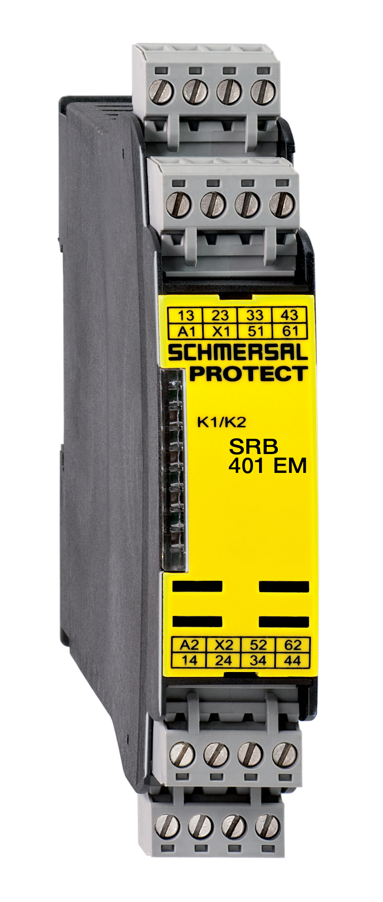
Product picture (catalogue individual photo)
Wiring example

Symbol (technical standard)

Schmersal India Pvt. Ltd., Plot No - G-7/1, Ranjangaon MIDC, Tal. - Shirur, Dist.- Pune 412 220
データと詳細は完全にチェックされました。画像は元の画像と異なる場合があります。技術的なデータはマニュアルで見られます。技術的に変更されたり、エラーの可能性があります。
Generated on 2025/04/09 18:19
最近見た製品