AES 1165-2196

AES 1165-2196
- Monitoring of BNS range magnetic safety sensors
- 1 safety contact, STOP 0
Ordering data
| Note (Delivery capacity) |
Non più disponibile! |
| Product type description |
AES 1165-2196 |
| Article number (order number) |
101170047 |
| EAN (European Article Number) |
4030661297057 |
| eCl@ss number, version 12.0 |
27-37-18-19 |
| eCl@ss number, version 11.0 |
27-37-18-19 |
| eCl@ss number, version 9.0 |
27-37-18-19 |
| ETIM number, version 7.0 |
EC001449 |
| ETIM number, version 6.0 |
EC001449 |
| Notice |
Discontinued product |
Approvals - Standards
| Certificates |
cULus |
General data
| Standards |
BG-GS-ET-14 BG-GS-ET-20 EN IEC 62061 EN ISO 13849-1 EN IEC 60947-5-1 EN IEC 60947-5-3 EN IEC 60947-5-5 EN IEC 60204-1 EN IEC 60947-1 |
| Climatic stress |
BG-GS-ET-14 IEC 60947-5-3 |
| Housing material |
materiale sintetico, termoplastica rinforzata con fibra di vetro, ventilata |
| Gross weight |
200 g |
General data - Features
| Wire breakage detection |
Sì |
| Cross-circuit detection |
Sì |
| Automatic reset function |
Sì |
| Reset after disconnection of supply voltage |
Sì |
| Earth connection detection |
Sì |
| Integral system diagnostics, status |
Sì |
| Number of inputs for NC |
2 |
| Number of inputs for NO |
1 |
| Number of LEDs |
1 |
| Number of safety contacts |
1 |
| Number of signalling outputs |
2 |
| Safety classification |
| Vorschriften |
EN ISO 13849-1 EN IEC 61508 |
| Stop-Category |
0 |
| Safety classification - Relay outputs |
| Performance Level, up to |
d |
| Category |
3 |
| PFH value |
1,00 x 10⁻⁷ /h |
| Notice |
valido per applicazioni fino a max. 50.000 cicli di commutazione / anno e con max. 80 % di carico del contatto |
| Safety Integrity Level (SIL), suitable for applications in |
2 |
| Mission time |
20 Year(s) |
Mechanical data
| Mechanical lifetime, minimum |
20.000.000 Operations |
| Mounting |
fissaggio rapido per guide DIN secondo DIN EN 60715 |
Mechanical data - Connection technique
| Terminal designations |
IEC/EN 60947-1 |
| Cable section, minimum |
0,25 mm² |
| Cable section, maximum |
2,5 mm² |
| Tightening torque of Clips |
0,6 Nm |
| Allowed type of cable |
solid single-wire flexible |
| Terminal (mechanical) |
1000075113 |
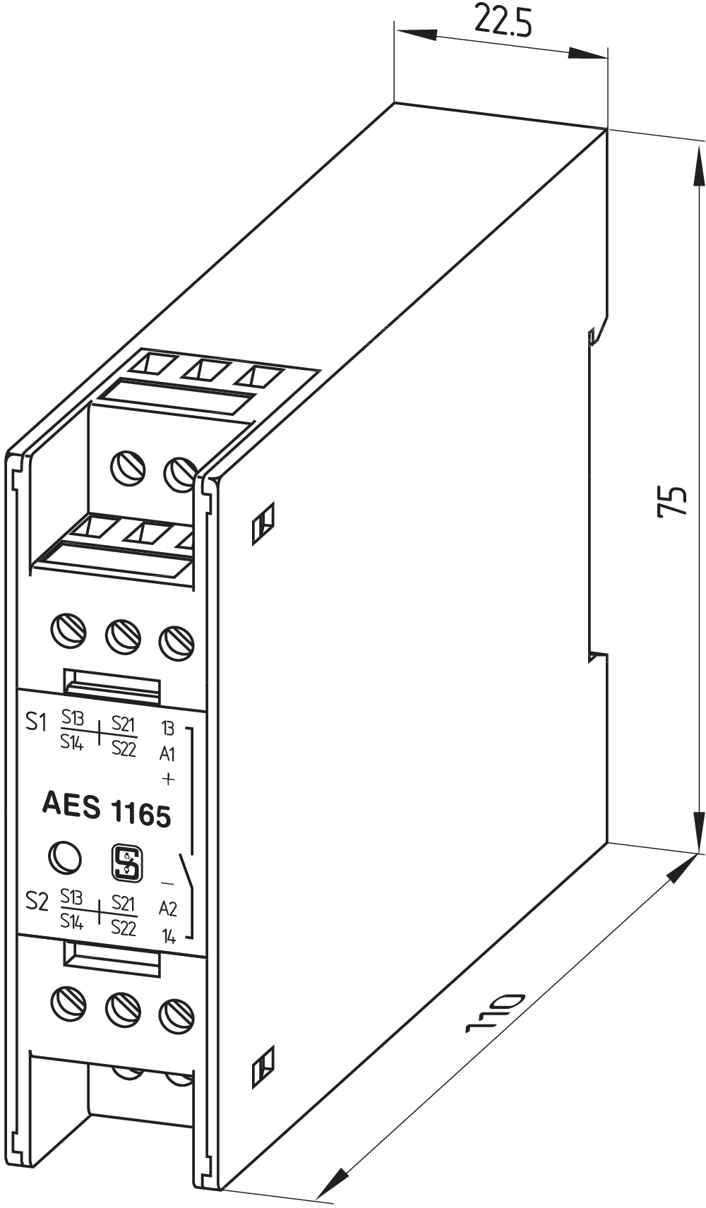
Mechanical data - Dimensions
| Width |
22,5 mm |
| Height |
100 mm |
| Depth |
121 mm |
Ambient conditions
| Degree of protection of the enclosure |
IP40 |
| Degree of protection of the installation space |
IP54 |
| Degree of protection of clips or terminals |
IP20 |
| Ambient temperature |
+0 ... +55 °C |
| Storage and transport temperature |
-25 ... +70 °C |
| Resistance to vibrations |
10...55 Hz, ampiezza 0,35 mm, ± 15 % |
| Restistance to shock |
30 g / 11 ms |
Ambient conditions - Insulation values
| Rated impulse withstand voltage Uimp |
4 kV |
| Overvoltage category |
III |
| Degree of pollution |
2 |
Electrical data
| Frequency range |
50 Hz 60 Hz |
| Operating voltage |
24 VAC -15 % / +10 % |
| Ripple voltage |
10 % |
| Thermal test current |
6 A |
| Rated operating voltage |
24 VAC |
| Rated operating voltage |
24 VDC |
| Rated AC voltage for controls, 50 Hz, minimum |
20.4 VAC |
| Rated control voltage at AC 50 Hz, maximum |
26.4 VAC |
| Rated AC voltage for controls, 60 Hz, minimum |
20.4 VAC |
| Rated control voltage at AC 60 Hz, maximum |
26.4 VAC |
| Rated AC voltage for controls at DC minimum |
20,4 VDC |
| Rated control voltage at DC, maximum |
28,8 VDC |
| Electrical power consumption |
5 W |
| Contact resistance, maximum |
0,1 Ω |
| Note (Contact resistance) |
in perfette condizioni |
| Drop-out delay in case of power failure, typically |
80 ms |
| Drop-out delay in case of emergency, typically |
20 ms |
| Pull-in delay at automatic start, maximum, typically |
100 ms |
| Pull-in delay at RESET, typically |
20 ms |
| Material of the contacts, electrical |
Ag-Ni 10 e 0,2 µm dorato |
Electrical data - Safe relay outputs
| Voltage, Utilisation category AC-15 |
230 VAC |
| Current, Utilisation category AC-15 |
6 A |
| Voltage, Utilisation category DC-13 |
24 VDC |
| Current, Utilisation category DC-13 |
6 A |
| Switching capacity, minimum |
10 VDC |
| Switching capacity, minimum |
10 mA |
| Switching capacity, maximum |
250 VAC |
| Switching capacity, maximum |
8 A |
Electrical data - Digital inputs
| Input signal, HIGH Signal "1" |
10 … 30 VDC |
| Input signal, LOW Signal "0" |
0 … 2 VDC |
| Conduction resistance, maximum |
40 Ω |
Electrical data - Digital Output
| Voltage, Utilisation category DC-12 |
24 VDC |
| Current, Utilisation category DC-12 |
0,1 A |
Electrical data - Relay outputs (auxiliary contacts)
| Switching capacity, maximum |
24 VDC |
| Switching capacity, maximum |
2 A |
Electrical data - Electromagnetic compatibility (EMC)
| EMC rating |
Direttiva EMC |
Integral system diagnosis (ISD)
| Note (ISD -Faults) |
I seguenti guasti vengono riconosciuti dal modulo di sicurezza e segnalati mediante ISD. |
| Faults |
Mancata eccitazione o diseccitazione del relè di sicurezza Mancata apertura o chiusura dei contatti porta Cortocircuiti o contatti trasversali nei conduttori degli interruttori Interruzione dei conduttori degli interruttori Guasti a circuiti d'ingresso oppure sui relè del modulo di sicurezza |
Other data
| Note (applications) |
Sensore di sicurezza Dispositivo di protezione |
Note
| Note (General) |
Soppresori induttivi (contattore, relè ecc.) vanno ripristinati con una commutazione idonea. |
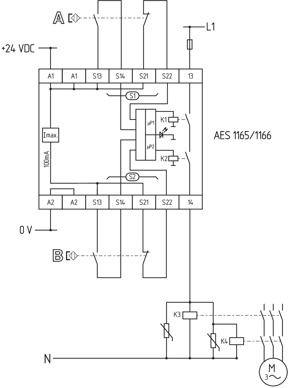
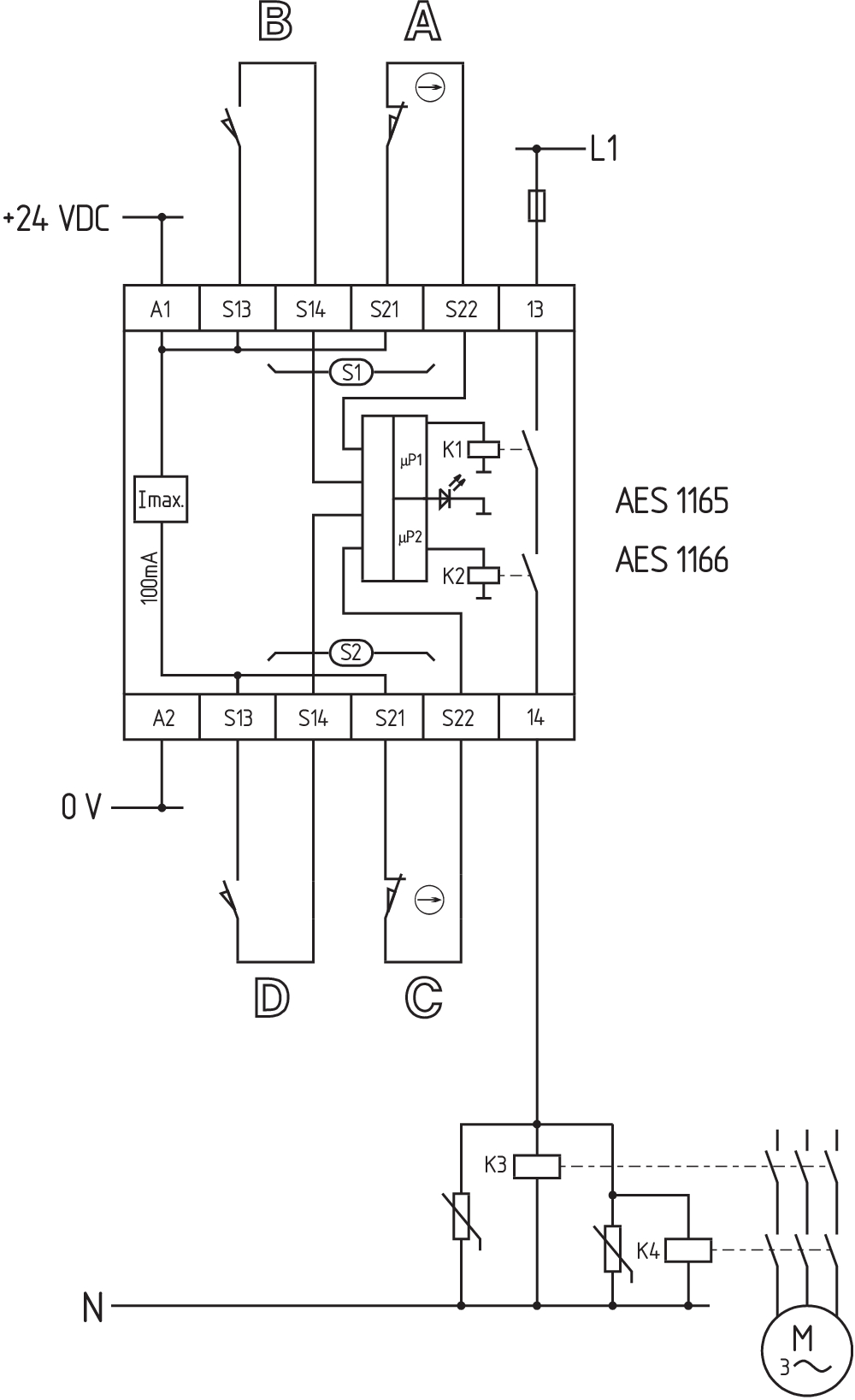
Wiring example
| Note (Wiring diagram) |
L'esempio di commutazione è rappresentato con dispositivi di sicurezza chiusi e in condizione senza tensione. Controllo di 2 dispositivo(i) di sicurezza con un sensore di sicurezza magnetico della serie BNS Se vengono utilizzati uno oppure due relè o contattori esterni per la commutazione del carico, il sistema può essere classificato nella categoria 3 sec. ISO 13849-1, se l'esclusione dell'errore "guasto dei/dei contattore/i esterno/i“ può venire motivato e documentato, per es. mediante l'impiego di contattori affidabili e sovradimensionati. Con un secondo contattore si raggiunge una maggiore sicurezza mediante la disattivazione ridondante del carico. Le tabelle ISD (diagnosi integrata nel sistema) per l'analisi delle segnalazioni di errore e le loro cause, sono riportate nell'appendice. Estensione del tempo di ritardo di sblocco: mediante lo spostamento di un ponticello sotto il coperchio della custodia è possibile impostare il tempo di ritardo di sblocco da 0,1 sec. a 1 sec.. Per la protezione di 2 ispositivi di sicurezza fino a PL 02 e categoria 03 |
Filtro lingua
Scheda Tecnica
Manuale d'istruzioni e dichiarazione UE di conformità
Certificazione UL
Esempio di collegamento (cablaggio elettrico)
Informazioni
Libreria SISTEMA-VDMA
Download dell'ultima versione di Adobe Reader
Immagine del prodotto (foto singola per catalogo)
Disegno quotato disp. di base
Esempio di azionamento
Esempio di azionamento
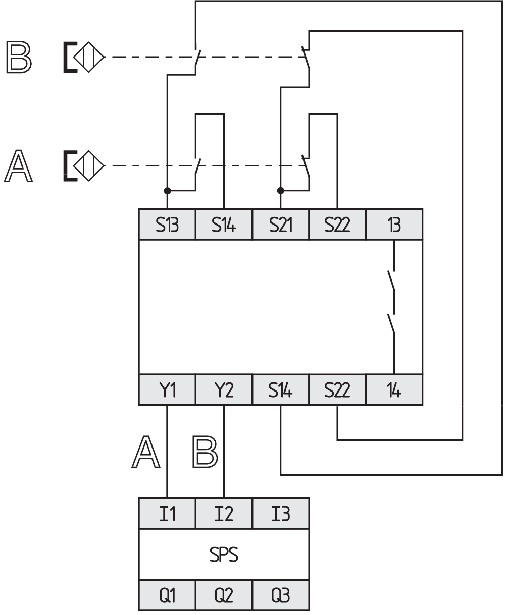
Esempio di azionamento
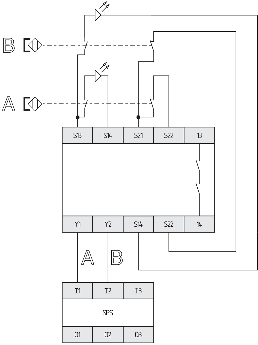
Esempio di azionamento
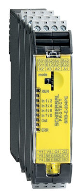
103008070 SRB-E-204PE
- Plug-in screw terminals with coding
- Input expander module
- 1 oder 2-channel control
- Monitoring of 4 sensors
- 2 Safety outputs
- 4 Signalling outputs

103009973 SRB-E-204ST
- Plug-in screw terminals with coding
- STOP 0 Function
- Monitoring of 4 sensors
- Start button / Auto-start
- 2 Safety outputs
- 4 Signalling outputs
| EU Declaration of Conformity |  |
| Original | K.A. Schmersal GmbH & Co. KG Möddinghofe 30 42279 Wuppertal Germany Internet: www.schmersal.com |
| Declaration: | We hereby certify that the hereafter described components both in their basic design and construction conform to the applicable European Directives. |
| Name of the component: | AES 1135/1136 AES 1165/1165-2250 AES 1235/1236 AES 1265/1265-2250 AES 2135 AES 2335/2365 AES 2535 |
| Type: | See ordering code |
| Description of the component: | Safety-monitoring module |
| Relevant Directives: | Machinery Directive | 2006/42/EC |
| EMC-Directive | 2014/30/EU | |
| RoHS-Directive | 2011/65/EU |
| Applied standards: | DIN EN 60947-5-1:2018 DIN EN ISO 13849-1:2016 DIN EN ISO 13849-2:2013 |
| Notified body, which approved the full quality assurance system, referred to in Appendix X, 2006/42/EC: | TÜV Rheinland Industrie Service GmbH Am Grauen Stein, 51105 Köln ID n°: 0035 |
| Person authorised for the compilation of the technical documentation: | Oliver Wacker Möddinghofe 30 42279 Wuppertal |
| Place and date of issue: | Wuppertal, January 31, 2024 |
 |
| Authorised signature Philip Schmersal Managing Director |
Schmersal India Pvt. Ltd., Plot No - G-7/1, Ranjangaon MIDC, Tal. - Shirur, Dist.- Pune 412 220
I dettagli e i dati qui riportati sono stati attentamente verificati. Le immagini possono differire dagli originali. Altri dati tecnici possono essere trovati nei manuali. Salvo modifiche tecniche o errori.
Generato il 27/08/2025, 09:07