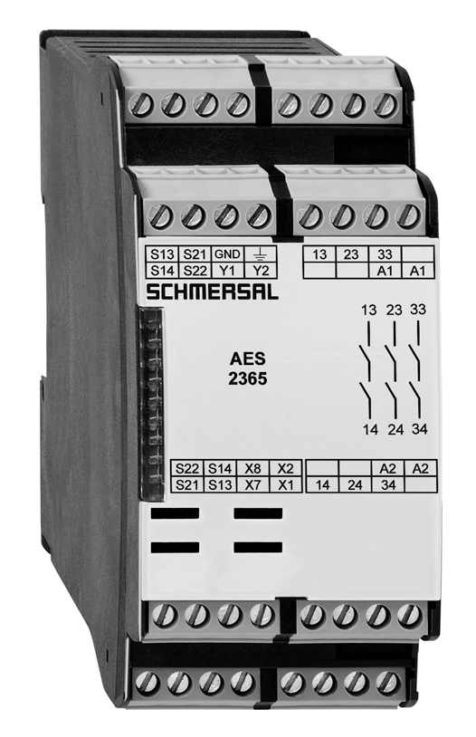
AES 2365 UE: 24...230V AC/DC

AES 2365 UE: 24...230V AC/DC
| Codice: AES 2(1)6(2) |
| (1) | |
| 3 | 3 circuiti di abilitazione |
| 215 | 5 circuiti di abilitazione |
| (2) | |
| 215 | senza test di avvio |
| 6 | con test di avvio |
- Monitoring of BNS range magnetic safety sensors
- 3 safety contacts, STOP 0
- 2 Signalling outputs
Ordering data
| Note (Delivery capacity) |
Prodotto fuori produzione |
| Product type description |
AES 2365 UE: 24...230V AC/DC |
| Article number (order number) |
101181686 |
| EAN (European Article Number) |
4030661323169 |
| eCl@ss number, version 12.0 |
27-37-18-19 |
| eCl@ss number, version 11.0 |
27-37-18-19 |
| eCl@ss number, version 9.0 |
27-37-18-19 |
| ETIM number, version 7.0 |
EC001449 |
| ETIM number, version 6.0 |
EC001449 |
| Notice |
Discontinued product |
Approvals - Standards
| Certificates |
cULus |
General data
| Standards |
BG-GS-ET-14 BG-GS-ET-20 EN IEC 62061 EN IEC 60947-5-1 EN IEC 60947-5-3 EN IEC 60947-5-5 EN IEC 61508 EN IEC 60204-1 EN IEC 60947-1 |
| Climatic stress |
EN 60068-2-3 BG-GS-ET-14 |
| Housing material |
materiale sintetico, termoplastica rinforzata con fibra di vetro |
| Gross weight |
310 g |
General data - Features
| Wire breakage detection |
Sì |
| Cross-circuit detection |
Sì |
| Feedback circuit |
Sì |
| Automatic reset function |
Sì |
| Reset after disconnection of supply voltage |
Sì |
| Integral system diagnostics, status |
Sì |
| Number of LEDs |
1 |
| Number of normally closed (NC) |
2 |
| Number of normally open (NO) |
2 |
| Number of undelayed semi-conductor outputs with signaling function |
2 |
| Number of safety contacts |
3 |
| Number of signalling outputs |
2 |
| Safety classification |
| Vorschriften |
EN ISO 13849-1 EN IEC 61508 |
| Stop-Category |
0 |
| Safety classification - Relay outputs |
| Performance Level, up to |
d |
| Category |
3 |
| PFH value |
1,00 x 10⁻⁷ /h |
| Notice |
valido per applicazioni fino a max. 50.000 cicli di commutazione / anno e con max. 80 % di carico del contatto |
| Safety Integrity Level (SIL), suitable for applications in |
2 |
| Mission time |
20 Year(s) |
Mechanical data
| Mechanical lifetime, minimum |
20.000.000 Operations |
| Mounting |
fissaggio rapido per guide DIN secondo DIN EN 60715 |
Mechanical data - Connection technique
| Terminal designations |
IEC/EN 60947-1 |
| Cable section, minimum |
0,25 mm² |
| Cable section, maximum |
2,5 mm² |
| Tightening torque of Clips |
0,6 Nm |
| Allowed type of cable |
solid single-wire flexible |
| Terminal (mechanical) |
1000075113 |
Mechanical data - Dimensions
| Width |
45 mm |
| Height |
100 mm |
| Depth |
121 mm |
Ambient conditions
| Degree of protection of the enclosure |
IP40 |
| Degree of protection of the installation space |
IP54 |
| Degree of protection of clips or terminals |
IP20 |
| Ambient temperature |
+0 ... +55 °C |
| Storage and transport temperature |
-25 ... +70 °C |
| Resistance to vibrations |
10...55 Hz, ampiezza 0,35 mm, ± 15 % |
| Restistance to shock |
30 g / 11 ms |
Ambient conditions - Insulation values
| Rated impulse withstand voltage Uimp |
4 kV |
| Overvoltage category |
III |
| Degree of pollution |
2 |
Electrical data
| Frequency range |
50 Hz 60 Hz |
| Type of voltage range |
AC DC |
| Thermal test current |
6 A |
| Rated operating voltage |
24 ... 230 VAC |
| Rated AC voltage for controls, 50 Hz, minimum |
20.4 VAC |
| Rated control voltage at AC 50 Hz, maximum |
253 VAC |
| Rated AC voltage for controls, 60 Hz, minimum |
20.4 VAC |
| Rated control voltage at AC 60 Hz, maximum |
253 VAC |
| Rated AC voltage for controls at DC minimum |
20,4 VDC |
| Rated control voltage at DC, maximum |
253 VDC |
| Electrical power consumption |
5 W |
| Contact resistance, maximum |
0,1 Ω |
| Note (Contact resistance) |
in perfette condizioni |
| Drop-out delay in case of power failure, typically |
80 ms |
| Drop-out delay in case of emergency, typically |
20 ms |
| Pull-in delay at automatic start, maximum, typically |
100 ms |
| Pull-in delay at RESET, typically |
20 ms |
| Material of the contacts, electrical |
Ag-Ni 10 e 0,2 µm dorato |
Electrical data - Safe relay outputs
| Voltage, Utilisation category AC-15 |
230 VAC |
| Current, Utilisation category AC-15 |
3 A |
| Voltage, Utilisation category DC-13 |
24 VDC |
| Current, Utilisation category DC-13 |
2 A |
| Switching capacity, minimum |
10 VDC |
| Switching capacity, minimum |
10 mA |
| Switching capacity, maximum |
250 VAC |
| Switching capacity, maximum |
8 A |
Electrical data - Digital inputs
| Input signal, HIGH Signal "1" |
10 … 30 VDC |
| Input signal, LOW Signal "0" |
0 … 2 VDC |
| Conduction resistance, maximum |
40 Ω |
Electrical data - Digital Output
| Voltage, Utilisation category DC-12 |
24 VDC |
| Current, Utilisation category DC-12 |
0,1 A |
Electrical data - Relay outputs (auxiliary contacts)
| Switching capacity, maximum |
24 VDC |
| Switching capacity, maximum |
2 A |
Electrical data - Electromagnetic compatibility (EMC)
| EMC rating |
Direttiva EMC |
Integral system diagnosis (ISD)
| Note (ISD -Faults) |
I seguenti guasti vengono riconosciuti dal modulo di sicurezza e segnalati mediante ISD. |
| Faults |
Mancata eccitazione o diseccitazione del relè di sicurezza Mancata apertura o chiusura dei contatti porta Cortocircuiti o contatti trasversali nei conduttori degli interruttori Interruzione dei conduttori degli interruttori Guasti a circuiti d'ingresso oppure sui relè del modulo di sicurezza |
Other data
| Note (applications) |
Sensore di sicurezza Dispositivo di protezione |
Note
| Note (General) |
Soppresori induttivi (contattore, relè ecc.) vanno ripristinati con una commutazione idonea. |
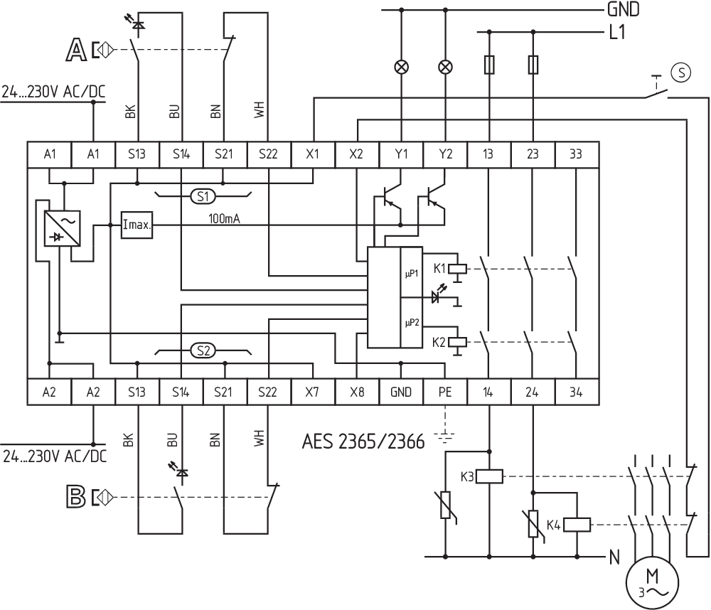
Wiring example
| Note (Wiring diagram) |
L'esempio di commutazione è rappresentato con dispositivi di sicurezza chiusi e in condizione senza tensione. Controllo di 2 dispositivo(i) di sicurezza con un sensore di sicurezza magnetico della serie BNS Per la messa in sicurezza di un dispositivo di protezione fino a PL "d" e Categoria 3 Le tabelle ISD (diagnosi integrata nel sistema) per l'analisi delle segnalazioni di errore e le loro cause, sono riportate nell'appendice. Pulsante di Start (S): Volendo, è possibile collegare al circuito di ripristino un pulsante di Start (NA). Con dispositivo di protezione chiuso, i contatti di sicurezza si chiudono solo dopo che è stato azionato il pulsante di Start. Prolungamento del ritardo di abilitazione: mediante un ponticello tra X7 e X8 è possibile modificare l'impostazione del ritardo di abilitazione da 0,1 s a 1 sec. Nel caso non venga collegato né un pulsante Start né un circuito di ritorno, è necessario inserire un ponticello tra X1 e X2. |
Filtro lingua
Scheda Tecnica
Manuale d'istruzioni e dichiarazione UE di conformità
Certificazione UL
Esempio di collegamento (cablaggio elettrico)
Diagramma della corsa di forza
Libreria SISTEMA-VDMA
Download dell'ultima versione di Adobe Reader
Immagine del prodotto (foto singola per catalogo)
Immagine del prodotto (foto singola per catalogo)
Esempio di azionamento

103009973 SRB-E-204ST
- Plug-in screw terminals with coding
- STOP 0 Function
- Monitoring of 4 sensors
- Start button / Auto-start
- 2 Safety outputs
- 4 Signalling outputs
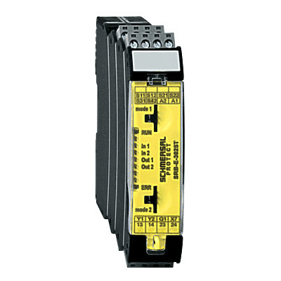
103041495 SRB-E-302ST
- Monitoring of 2 sensors STOP 0
- 1 oder 2-channel control
- Start button / Auto-start
- 2 Safety contacts, 1 Safety Output
- 2 Signalling outputs
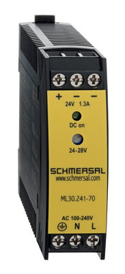
103015923 ML30.241-70
- 1-phase DIN rail power supplies
- AC 100-240V Wide-range input
- DC Output 24-28VDC / 1,3-1,1A / 30W
- Efficiency up to 89,4%
- Width only 22,5mm
| EU Declaration of Conformity |  |
| Original | K.A. Schmersal GmbH & Co. KG Möddinghofe 30 42279 Wuppertal Germany Internet: www.schmersal.com |
| Declaration: | We hereby certify that the hereafter described components both in their basic design and construction conform to the applicable European Directives. |
| Name of the component: | AES 1135/1136 AES 1165/1165-2250 AES 1235/1236 AES 1265/1265-2250 AES 2135 AES 2335/2365 AES 2535 |
| Type: | See ordering code |
| Description of the component: | Safety-monitoring module |
| Relevant Directives: | Machinery Directive | 2006/42/EC |
| EMC-Directive | 2014/30/EU | |
| RoHS-Directive | 2011/65/EU |
| Applied standards: | DIN EN 60947-5-1:2018 DIN EN ISO 13849-1:2016 DIN EN ISO 13849-2:2013 |
| Notified body, which approved the full quality assurance system, referred to in Appendix X, 2006/42/EC: | TÜV Rheinland Industrie Service GmbH Am Grauen Stein, 51105 Köln ID n°: 0035 |
| Person authorised for the compilation of the technical documentation: | Oliver Wacker Möddinghofe 30 42279 Wuppertal |
| Place and date of issue: | Wuppertal, January 31, 2024 |
 |
| Authorised signature Philip Schmersal Managing Director |
Schmersal India Pvt. Ltd., Plot No - G-7/1, Ranjangaon MIDC, Tal. - Shirur, Dist.- Pune 412 220
I dettagli e i dati qui riportati sono stati attentamente verificati. Le immagini possono differire dagli originali. Altri dati tecnici possono essere trovati nei manuali. Salvo modifiche tecniche o errori.
Generato il 01/09/2025, 18:41