CSP 11-34F2-D-M-ST
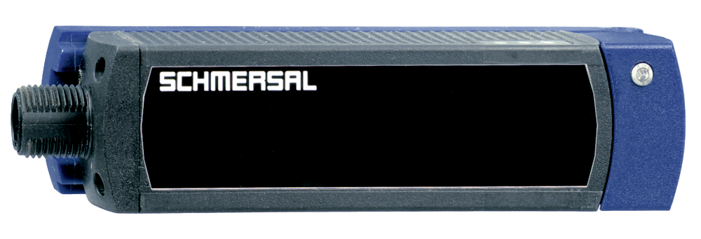
CSP 11-34F2-D-M-ST
- 1 x connector plug M12, 8-pole
- Actuation from side
- with On-site acknowledgment
- NOTICE: Not available! (Replacement: RSS 36 I)
- Thermoplastic enclosure
- Electronic contact-free, coded system
- Tampering protection by paired coding of sensor and actuator
- Misaligned actuation possible
- High repeat accuracy of the switching points
- Max. length of the sensor chain 200 m
- 2 short-circuit proof PNP safety outputs
- Integral cross-short, wire-breakage and external voltage monitoring of the safety cables up to the control cabinet
Ordering data
| Note (Delivery capacity) |
Non più disponibile! |
| Product type description |
CSP 11-34F2-D-M-ST |
| Article number (order number) |
101208005 |
| EAN (European Article Number) |
4030661382029 |
| eCl@ss number, version 12.0 |
27-27-26-06 |
| eCl@ss number, version 11.0 |
27-27-24-04 |
| eCl@ss number, version 9.0 |
27-27-24-04 |
| ETIM number, version 7.0 |
EC001487 |
| ETIM number, version 6.0 |
EC001487 |
Approvals - Standards
| Certificates |
cULus |
General data
| Standards |
EN ISO 13849-1 EN IEC 60947-5-3 EN IEC 61508 |
| Working principle |
induttivo |
| Housing construction form |
parallelepipedo |
| Installation conditions (mechanical) |
non allineato |
| Sensor topology |
Sensore per azionamento in serie |
| Housing material |
materiale sintetico, termoplastica rinforzata con fibra di vetro |
| Active area |
materiale sintetico, termoplastica rinforzata con fibra di vetro |
| Reaction time, maximum |
30 ms |
| Duration of risk, maximum |
60 ms |
| Gross weight |
140 g |
General data - Features
| Diagnostic output |
Sì |
| Short circuit detection |
Sì |
| Cross-circuit detection |
Sì |
| Safety functions |
Sì |
| Cascadable |
Sì |
| Input for reset pushbutton, with edge monitoring |
Sì |
| Input for enabling pushbutton, suitable for automatic start |
Sì |
| On-site acknowledgment |
Sì |
| Integral system diagnostics, status |
Sì |
| Number of LEDs |
3 |
| Number of semi-conductor outputs with signaling function |
1 |
| Number of fail-safe digital outputs |
2 |
| Number of series-wiring of sensors |
31 |
| Safety classification |
| Vorschriften |
EN IEC 60947-5-3 EN IEC 61508 |
| Performance Level, up to |
e |
| Category |
4 |
| PFH value |
3,60 x 10⁻⁹ /h |
| Safety Integrity Level (SIL), suitable for applications in |
3 |
| Mission time |
20 Year(s) |
Mechanical data
| Actuating panels |
lateralmente |
| Active area |
lateralmente |
Mechanical data - Switching distances
| Switch distance, typical |
11 mm |
| Assured switching distance "ON" Sao |
8 mm |
| Assured switching distance "OFF" Sar |
15 mm |
| Note (switching distance) |
All switching distances in accordance EN IEC 60947-5-3 |
| Hysteresis (Switching distance), maximum |
1,5 mm |
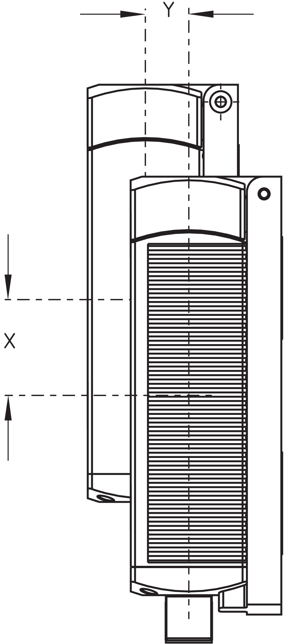
| Repeat accuracy R |
0,5 mm |
| Note (Repeat accuracy R) |
Spostamento assiale laterale: La superficie laterale lunga permette un disallineamento in altezza massimo (x) tra sensore ed azionatore di 30 mm (ad es. tolleranza di montaggio o per abbassamento della porta di sicurezza). Lo scostamento trasversale (Y) è max. ± 8 mm. |
Mechanical data - Connection technique
| Note (length of the sensor chain) |
Cable length and cross-section change the voltage drop dependiing on the output current |
| Termination |
Connettore maschio incorporato M12, 8 poli |
Mechanical data - Dimensions
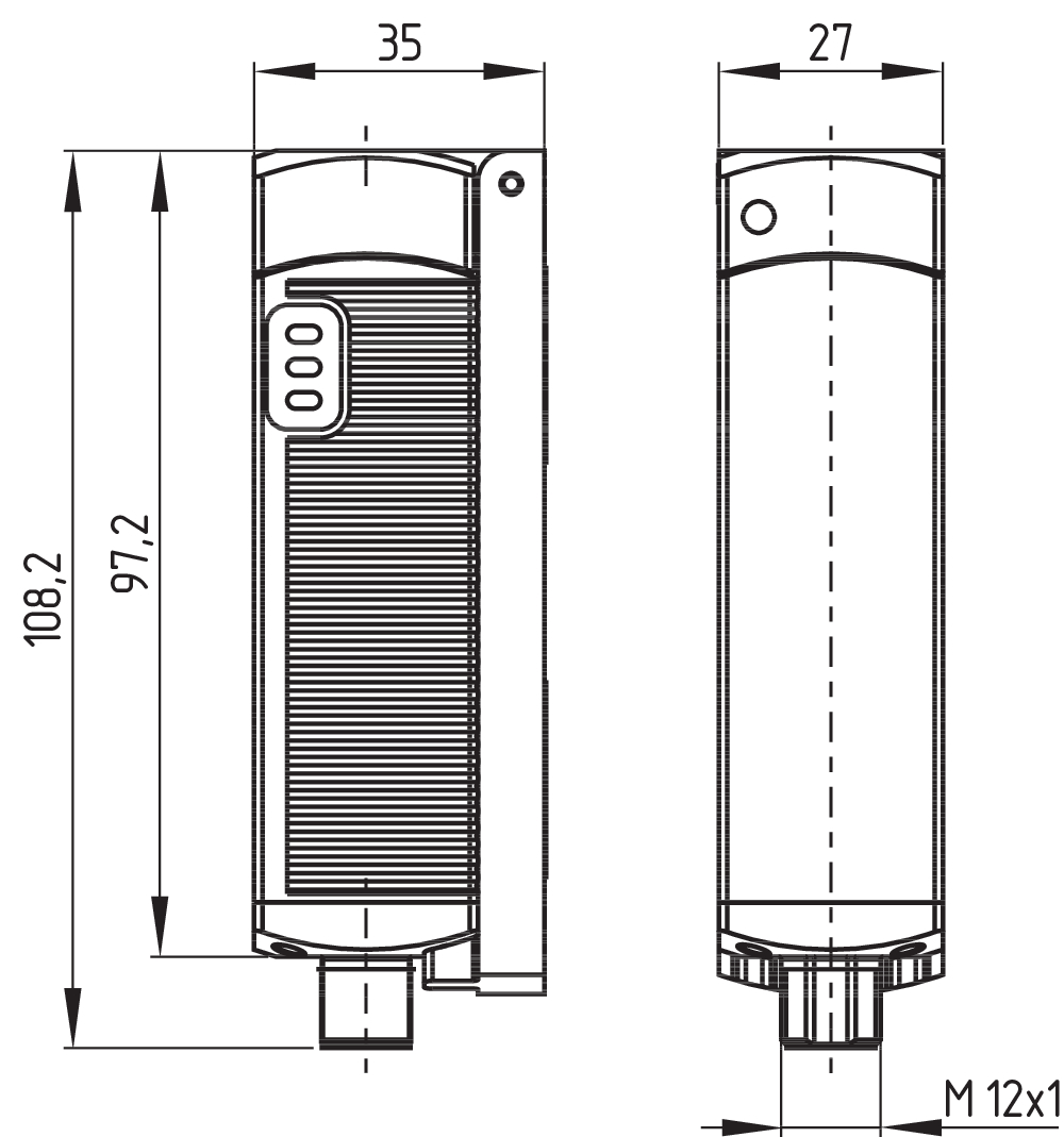
| Length of sensor |
27 mm |
| Width of sensor |
35 mm |
| Height of sensor |
108,2 mm |
Ambient conditions
| Degree of protection |
IP65 IP67 |
| Ambient temperature |
-25 ... +70 °C |
| Storage and transport temperature |
-25 ... +85 °C |
| Resistance to vibrations |
10…55 Hz, ampiezza 1 mm |
| Restistance to shock |
30 g / 11 ms |
| Protection class |
II |
Ambient conditions - Insulation values
| Rated insulation voltage Ui |
32 VAC/DC |
| Rated impulse withstand voltage Uimp |
0,8 kV |
| Overvoltage category |
III |
| Degree of pollution |
3 |
Electrical data
| Operating voltage |
24 VDC -15 % / +10 % |
| No-load supply current I0, typical |
100 mA |
| Rated operating voltage |
24 VDC |
| Operating current |
600 mA |
| Required rated short-circuit current |
100 A |
| Utilisation category DC-12 |
24 VDC |
| Utilisation category DC-12 |
0,05 A |
| Utilisation category DC-13 |
24 VDC |
| Utilisation category DC-13 |
0,05 A |
| Note (Electrical data, Fuse rating) |
(Interruttore) |
| Switching frequency, approx. |
3 Hz |
| Utilisation category DC-12 |
24 VDC / 0,05 A |
| Electrical fuse rating, maximum |
2 A |
Electrical data - Safety digital outputs
| Rated operating current (safety outputs) |
250 mA |
| Output current, (fail-safe output), maximum |
0,25 A |
| Design of control elements |
con commutazione p |
| Voltage drop Ud, maximum |
0,5 V |
| Leakage current Ir, maximum |
0,5 mA |
| Voltage, Utilisation category DC-12 |
24 VDC |
| Current, Utilisation category DC-12 |
0,25 A |
| Voltage, Utilisation category DC-13 |
24 VDC |
| Current, Utilisation category DC-13 |
0,25 A |
Electrical data - Digital Output
| Design of control elements |
commutazione p |
Electrical data - Diagnostic outputs
| Operating current |
50 mA |
| Voltage drop Ud, maximum |
5 V |
| Voltage, Utilisation category DC-12 |
24 VDC |
| Current, Utilisation category DC-12 |
0,05 A |
Electrical data - Electromagnetic compatibility (EMC)
| Interfering radiation |
IEC 61000-6-4 |
| EMC rating |
IEC 61000-6-2 |
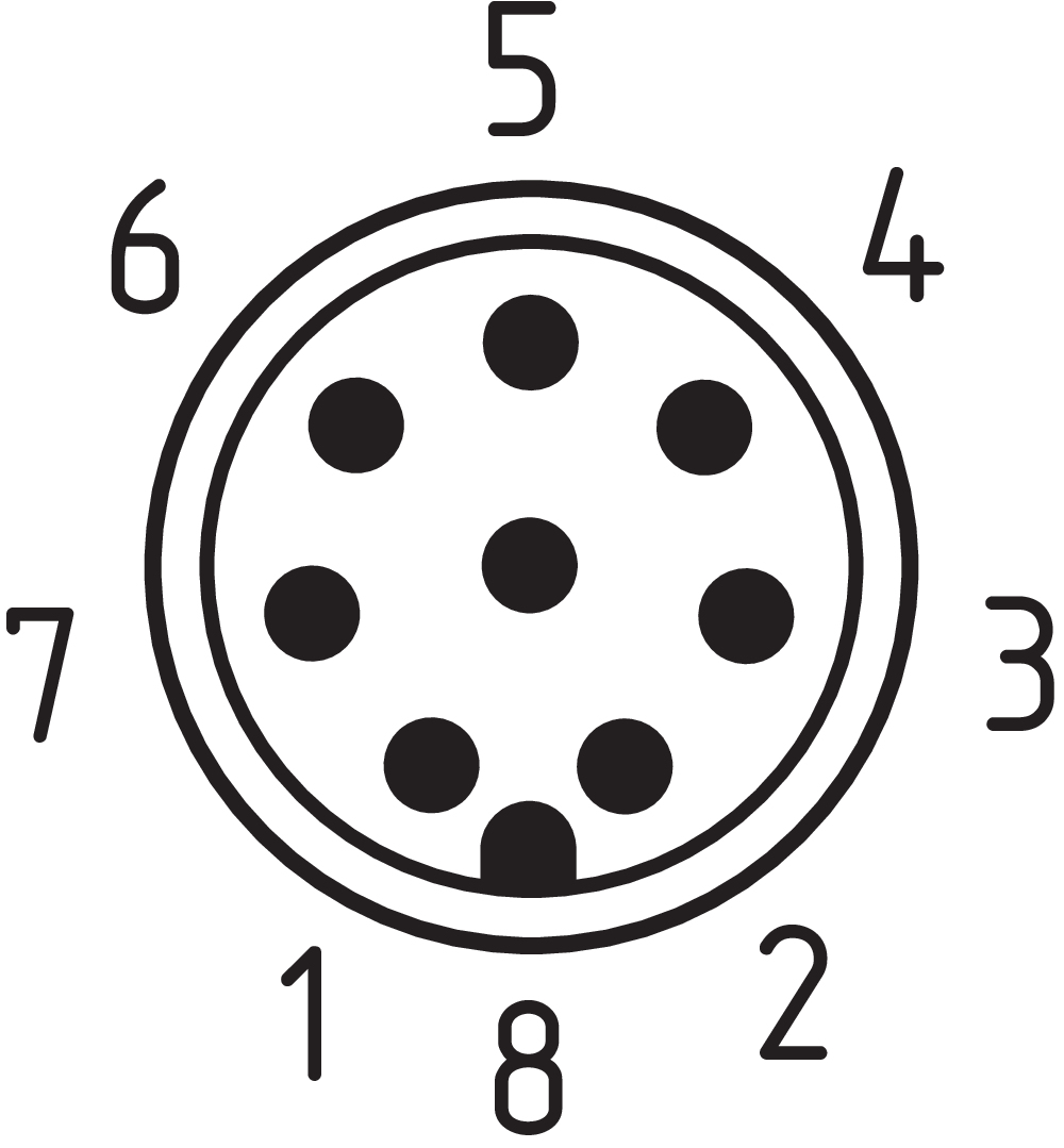
Pin assignment
| PIN 1 |
1A1 Ue: (1) |
| PIN 2 |
X1 Entrata di sicurezza 1 |
| PIN 3 |
A2 GND |
| PIN 4 |
Y1 Uscita di sicurezza 1 |
| PIN 5 |
OUT Uscita di diagnosi OUT |
| PIN 6 |
X2 Entrata di sicurezza 2 |
| PIN 7 |
Y2 Uscita di sicurezza 2 |
| PIN 8 |
IN Conferma in loco |
Scope of delivery
| Scope of delivery |
Actuator must be ordered separately. |
Accessory
| Recommendation (actuator) |
CSP 34-S-1 |
| Recommended safety switchgear |
PROTECT PSC1 SRB-E-301ST SRB-E-201LC |
Note
| Note (General) |
In caso di sorveglianza della porta di protezione mediante un sensore di sicurezza CSP 34F2, è necessario collocare ad esempio un pulsante di reset/conferma sulla porta di protezione, in modo tale da garantire la visibilità dell'area di pericolo. Con il pulsante si genera un segnale da 24 VDC sull'ingresso di conferma del CSP 34F2. Con la porta chiusa, le uscite di sicurezza vengono abilitate con un fronte del segnale negativo. In seguito all'apertura della porta è richiesta una nuova conferma prima della successiva abilitazione. Conferma in loco |
Filtro lingua
Scheda Tecnica
Manuale d'istruzioni e dichiarazione UE di conformità
Certificazione UL
Esempio di collegamento (cablaggio elettrico)
Brochure
Libreria SISTEMA-VDMA
Download dell'ultima versione di Adobe Reader
Immagine del prodotto (foto singola per catalogo)
Disegno quotato disp. di base
Funzioni
Clipart
Diagramma curve caratteristiche

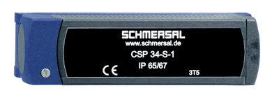
101208465 CSP 34-S-1-02
- Actuation from side
- actuator code 2
- 20 different actuator codes available
101208466 CSP 34-S-1-03
- Actuation from side
- actuator code 3
- 20 different actuator codes available
101208467 CSP 34-S-1-04
- Actuation from side
- actuator code 4
- 20 different actuator codes available
101208468 CSP 34-S-1-05
- Actuation from side
- actuator code 5
- 20 different actuator codes available
101208469 CSP 34-S-1-06
- Actuation from side
- actuator code 6
- 20 different actuator codes available
101208470 CSP 34-S-1-07
- Actuation from side
- actuator code 7
- 20 different actuator codes available
101208471 CSP 34-S-1-08
- Actuation from side
- actuator code 8
- 20 different actuator codes available
101208472 CSP 34-S-1-09
- Actuation from side
- actuator code 9
- 20 different actuator codes available
101208473 CSP 34-S-1-10
- Actuation from side
- actuator code 10
- 20 different actuator codes available
101208474 CSP 34-S-1-11
- Actuation from side
- actuator code 11
- 20 different actuator codes available
101208475 CSP 34-S-1-12
- Actuation from side
- actuator code 12
- 20 different actuator codes available
101208476 CSP 34-S-1-13
- Actuation from side
- actuator code 13
- 20 different actuator codes available
101208477 CSP 34-S-1-14
- Actuation from side
- actuator code 14
- 20 different actuator codes available
101208478 CSP 34-S-1-15
- Actuation from side
- actuator code 15
- 20 different actuator codes available
101208479 CSP 34-S-1-16
- Actuation from side
- actuator code 16
- 20 different actuator codes available
101208480 CSP 34-S-1-17
- Actuation from side
- actuator code 17
- 20 different actuator codes available
101208481 CSP 34-S-1-18
- Actuation from side
- actuator code 18
- 20 different actuator codes available
101208464 CSP 34-S-1-01
- Actuation from side
- actuator code 1
- Sensor and actuator must be ordered separately.

103009970 SRB-E-201LC
- Plug-in screw terminals with coding
- STOP 0 Function
- 1 oder 2-channel control
- Start button / Auto-start
- 2 Safety outputs 2 A
- 1 Signalling output

103009973 SRB-E-204ST
- Plug-in screw terminals with coding
- STOP 0 Function
- Monitoring of 4 sensors
- Start button / Auto-start
- 2 Safety outputs
- 4 Signalling outputs

103007672 SRB-E-301ST
- Plug-in screw terminals with coding
- STOP 0 Function
- 1 oder 2-channel control
- Start button / Auto-start
- 1 Auxiliary contact
- 3 safety contacts
Schmersal India Pvt. Ltd., Plot No - G-7/1, Ranjangaon MIDC, Tal. - Shirur, Dist.- Pune 412 220
I dettagli e i dati qui riportati sono stati attentamente verificati. Le immagini possono differire dagli originali. Altri dati tecnici possono essere trovati nei manuali. Salvo modifiche tecniche o errori.
Generato il 20/07/2025, 15:20