AZ201-I2-SK-T-1P2P
AZ201-I2-SK-T-1P2P
| Codice: AZ201(1)-T-(2) |
| (1) | |
| SK | morsetti a vite |
| CC | morsetti a molla |
| ST1 | connettore M23, x 1, 8+1 poli |
| ST2 | connettore M12, x 1, 8 poli |
| (2) | |
| 1P2P | 1 uscita di diagnosi e 2 uscite di sicurezza, commutazione p |
| SD2P | Uscita di diagnosi seriale e 2 uscite di sicurezza, a commutazione p |
- Codifica ripetibile individuale con tecnologia RFID
- Livello di codifica ALTO secondo ISO 14119
- Custodia in plastica
- Protezione da manomissione con la tecnologia RFID in base alle necessità
- Max. lunghezza della catena di sensori 200 m
- Collegamento in serie autocontrollato
- 3 LEDs per l'indicazione delle condizioni d'esercizio
- La tecnica sensoriale permette lo spostamento di azionatore e ritenuta in verticale di ± 5 mm ed in orizzontale di ± 3 mm
- Adatto per porte scorrevoli e ruotabili
- Diagnosi intelligente
Dati per l'ordine
| Codice |
AZ201-I2-SK-T-1P2P |
| Codice articolo (codice d'ordine) |
103015818 |
| EAN (European Article Number) |
4030661504322 |
| eCl@ss number, version 12.0 |
27-27-26-02 |
| eCl@ss number, version 11.0 |
27-27-26-02 |
| Numero eCl@ss, versione 9.0 |
27-27-26-02 |
| ETIM number, version 7.0 |
EC002592 |
| ETIM number, version 6.0 |
EC002592 |
Omologazioni - Prescrizioni
| Certificazioni |
TÜV cULus FCC IC ANATEL |
Dati generali
| Prescrizioni |
EN ISO 13849-1 EN ISO 14119 EN IEC 60947-5-3 EN IEC 61508 |
|
| informazioni generali |
Codifica individuale, Teach-in ripetibile |
|
| Livello di codifica secondo EN ISO 14119 |
alto |
|
| principio d'azione |
RFID, 125 kHz |
|
| Transmitter output RFID, maximum |
-6 dB/m |
|
| Materiale della custodia |
materiale sintetico, termoplastica rinforzata con fibra di vetro |
|
| Tempo di rischio, massimo |
200 ms |
|
|
100 ms |
|
|
0,5 ms |
|
| Peso lordo |
403 g |
Dati generali - Caratteristiche
| Riconoscimento cortocircuiti |
Sì |
| Riconoscimento di corto circuito |
Sì |
| Azionamento in serie |
Sì |
| Funzioni di sicurezza |
Sì |
| Display integrato, stato |
Sì |
| quantità di contatti di sicurezza |
2 |
Osservazioni per la sicurezza
| Norma, Prescrizioni |
EN ISO 13849-1 EN IEC 61508 |
| Performance Level, fino a |
e |
| Categoria secondo EN ISO 13849 |
4 |
| Valore PFH |
1,90 x 10⁻⁹ /h |
| Valore PFD |
1,60 x 10⁻⁴ |
Safety Integrity Level (SIL), idoneo per applicazioni in |
3 |
| Durata di utilizzo |
20 Anno(i) |
Dati meccanici
| Durata meccanica, minimo |
1.000.000 manovre |
| Forza di ritenuta |
30 N |
| Velocità di azionamento, massima |
0,2 m/s |
| Versione delle viti di fissaggio |
2x M6 |
| Tightening torque of the fastening screws for the housing cover, minimum |
0,7 Nm |
| Tightening torque of the fastening screws for the housing cover, maximum |
1 Nm |
| Note |
Torx T10 |
Dati meccanici - Distanze di commutazione secondo EN IEC 60947-5-3
| Campo, distanza di commutazione sicura "ON" |
4 mm |
| Distanza di commutazione sicura "OFF" |
30 mm |
| Isteresi (Distanza di commutazion), massimo |
1,5 mm |
| Precisione di ripetizione R |
0,5 mm |
Dati meccanici - Tecnologia di collegamento
| Length of sensor chain, maximum |
200 m |
| Note (length of the sensor chain) |
Cable length and cross-section change the voltage drop dependiing on the output current |
| Note (series-wiring) |
Unlimited number of devices, oberserve external line fusing, max. 31 devices in case of serial diagnostic SD |
| Connettore di collegamento |
Collegamento a vite M20 x 1.5 |
| Sezione di collegamento, minima |
0,25 mm² |
| Sezione di collegamento, massimo |
1,5 mm² |
| Osservazioni (Sezione di collegamento) |
Tutte le indicazioni sulla sezione del cavo includono le bussole del conduttore. |
| Sezione conduttore, minimo |
23 AWG |
| Sezione conduttore, massimo |
15 AWG |
| Wire cross-section |
23 ... 15 AWG |
| Allowed type of cable |
solid single-wire solid multi-wire flexible |
Dati meccanici - Dimensioni
| lunghezza del sensore |
50 mm |
| larghezza del sensore |
40 mm |
| altezza del sensore |
220 mm |
Condizioni ambientali
| Grado di protezione |
IP67 IP66 |
| Ambient temperature |
-25 ... +70 °C |
| Storage and transport temperature |
-25 ... +85 °C |
| Umidità relativa, massima |
93 % |
| Osservazioni (umidità relativa) |
non condensante non gela |
| Resistenza alle vibrazioni secondo EN 60068-2-6 |
10 … 150 Hz, ampiezza 0,35 mm |
| resistenza a urti |
30 g / 11 ms |
| Classe di protezione |
III |
| Altitudine di installazione ammissibile s.l.m., massima |
2.000 m |
Condizioni ambientali - Valori di isolamento
| Tensione d'isolamento nominale |
32 VDC |
| Resistenza alla tensione impulsiva nominale |
0,8 kV |
| Categoria di sovratensione |
III |
| Grado di inquinamento secondo VDE 0100 |
3 |
Dati elettrici
| Operating voltage |
24 VDC -15 % / +10 % |
| No-load supply current I0, typical |
50 mA |
| Rated operating voltage |
24 VDC |
| Corrente di funzionamento |
700 mA |
| Corrente nominale di cortocircuito condizionata secondo EN 60947-5-1 |
100 A |
| External wire and device fuse rating |
4A gG |
| Ritardo di disponibilità, massimo |
4.000 ms |
| Frequenza di commutaz, massimo |
1 Hz |
Dati elettrici - Ingressi digitali sicuri
| Denominazione, Ingressi di sicurezza |
X1 and X2 |
| Soglie di commutazione |
−3 V … 5 V (Low) 15 V … 30 V (High) |
| Assorbimento di corrente a 24 V |
5 mA |
| Test pulse duration, maximum |
1 ms |
| Test pulse interval, minimum |
100 ms |
| Classificazione ZVEI CB24I, Sink |
C1 |
| Classificazione ZVEI CB24I, Fonte |
C1 C2 C3 |
Dati elettrici - Uscite digitali sicure
| Denominazione, Uscite di sicurezza |
Y1 e Y2 |
| Corrente d'esercizio nominale (uscite di sicurezza) |
250 mA |
| Versione |
resistente a cortocircuito, con commutazione p |
| Caduta di tensione Ud, massimo |
4 V |
| corrente residua |
0,5 mA |
| Tensione, Categoria d'utilizzo DC-13 |
24 VDC |
| Corrente, categoria d'utilizzo DC-13 |
0,25 A |
| Test pulse interval, typical |
1000 ms |
| Test pulse duration, maximum |
0,5 ms |
| Classificazione ZVEI CB24I, Fonte |
C2 |
| Classificazione ZVEI CB24I, Sink |
C1 C2 |
Dati elettrici - Uscita di diagnosi
| Designazione, Uscite diagnostiche |
OUT |
| Corrente di funzionamento |
50 mA |
| Versione |
resistente a cortocircuito, con commutazione p |
| Caduta di tensione Ud, massimo |
4 V |
| Tensione, Categoria d'utilizzo DC-13 |
24 VDC |
| Corrente, categoria d'utilizzo DC-13 |
0,05 A |
Segnalazione di stato
| Osservazioni (Indicatori di stato a LED) |
Stato operativo: LED giallo Errore malfunzionamento: LED rosso Tensione di alimentazione UB: LED verde |
Fornitura
| Fornitura |
Actuator must be ordered separately. |
Accessori
| Raccomandazione, (Azionatore) |
AZ/AZM201-B1 AZ/AZM201-B30 |
Filtro lingua
Scheda Tecnica
Manuale d'istruzioni e dichiarazione UE di conformità
Certificazione TÜV
Certificazione UL
Dichiarazione di conformità UE
ANATEL certification
Libreria SISTEMA-VDMA
Download dell'ultima versione di Adobe Reader
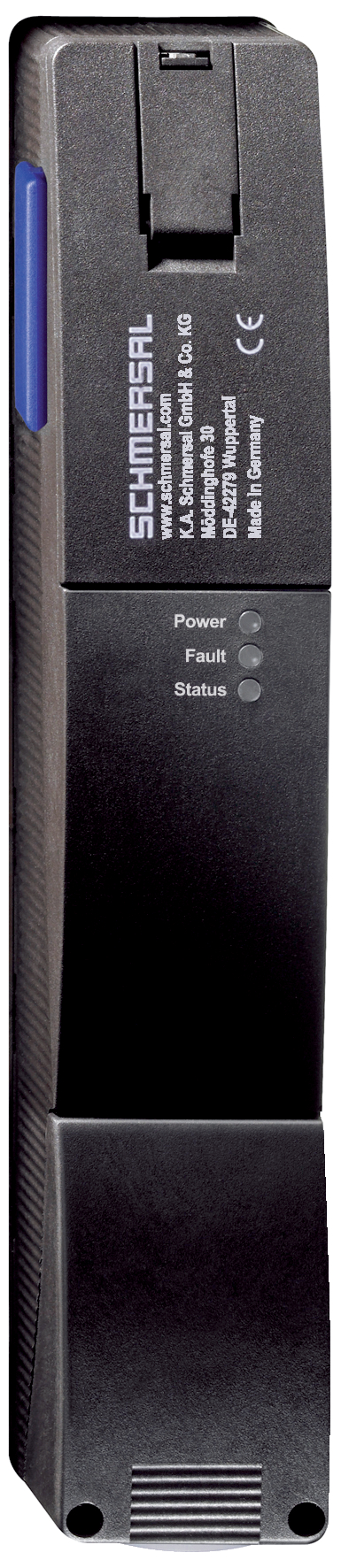
Immagine del prodotto (foto singola per catalogo)
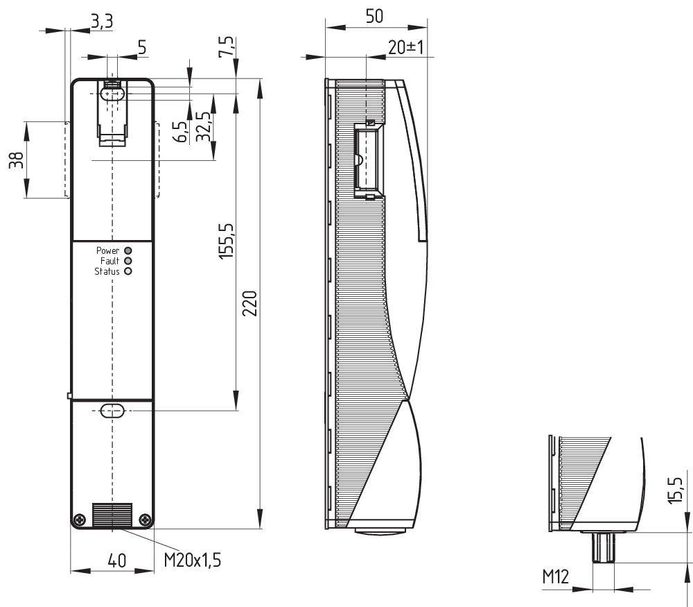
Disegno quotato disp. di base
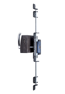
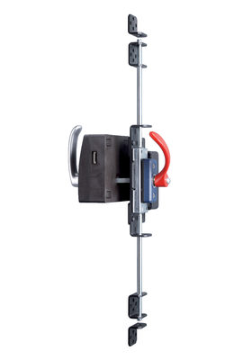
Esempio di montaggio

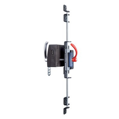
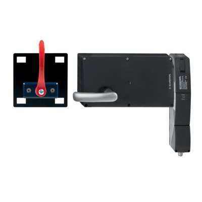
103015820 AZ/AZM201-B30-LTAG1P30
- per cerniera porta a sinistra
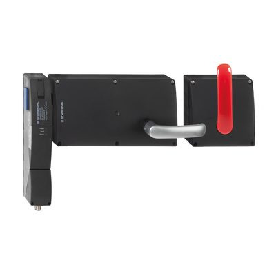
- con Maniglia
- Azionatore per dispositivo di protezione girevole
- Azionamento semplice ed intuitivo
- Nessun pericolo di infortunio con l' azionatore sporgente
- Risparmio su ulteriori maniglie
- non entra nello spazio tra porta e stipite
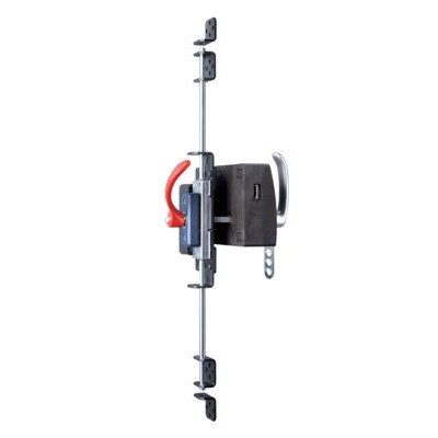
103015821 AZ/AZM201-B30-LTAG1P31
- per cerniera porta a sinistra
- con maniglia della porta e maniglia per l'uscita di emergenza
- Azionatore per dispositivo di protezione girevole
- Azionamento semplice ed intuitivo
- Nessun pericolo di infortunio con l' azionatore sporgente
- Risparmio su ulteriori maniglie
- non entra nello spazio tra porta e stipite
103015822 AZ/AZM201-B30-LTAG1P31-SZ
- per cerniera porta a sinistra
- con maniglia della porta e maniglia per l'uscita di emergenza
- Con pinza di bloccaggio integrata
- Azionatore per dispositivo di protezione girevole
- Azionamento semplice ed intuitivo
- Nessun pericolo di infortunio con l' azionatore sporgente
- Risparmio su ulteriori maniglie
- non entra nello spazio tra porta e stipite
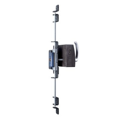
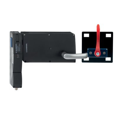
103015823 AZ/AZM201-B30-RTAG1P30
- per cerniera porta a destra
- con Maniglia
- Azionatore per dispositivo di protezione girevole
- Azionamento semplice ed intuitivo
- Nessun pericolo di infortunio con l' azionatore sporgente
- Risparmio su ulteriori maniglie
- non entra nello spazio tra porta e stipite

103015824 AZ/AZM201-B30-RTAG1P31
- per cerniera porta a destra
- con maniglia della porta e maniglia per l'uscita di emergenza
- Azionatore per dispositivo di protezione girevole
- Azionamento semplice ed intuitivo
- Nessun pericolo di infortunio con l' azionatore sporgente
- Risparmio su ulteriori maniglie
- non entra nello spazio tra porta e stipite
103015825 AZ/AZM201-B30-RTAG1P31-SZ
- per cerniera porta a destra
- con maniglia della porta e maniglia per l'uscita di emergenza
- Con pinza di bloccaggio integrata
- Azionatore per dispositivo di protezione girevole
- Azionamento semplice ed intuitivo
- Nessun pericolo di infortunio con l' azionatore sporgente
- Risparmio su ulteriori maniglie
- non entra nello spazio tra porta e stipite

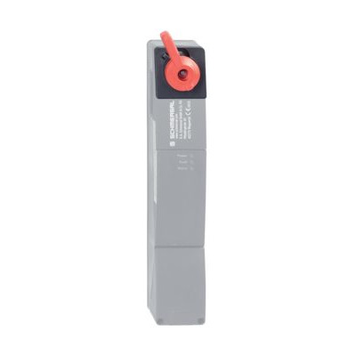
103004966 RF-AZM200/201-T
- Successiva estensione delle funzioni dell'elettroserratura AZM200 / AZM201
- Kit di retrofitting sblocco di fuga
103003543 RF-AZM200/201-N
- Kit di retrofitting sblocco di emergenza
- Successiva estensione delle funzioni dell'elettroserratura AZM200 / AZM201
- Sigillatura opzionale possibile
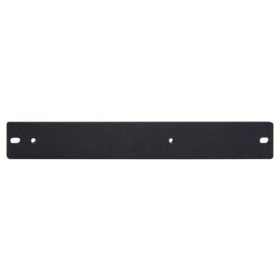
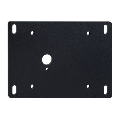
101188600 PIASTRA DI MONTAGGIO AZ/AZM200
- Piastra di montaggio per un'installazione facile e veloce
- Metallo, verniciato a polvere
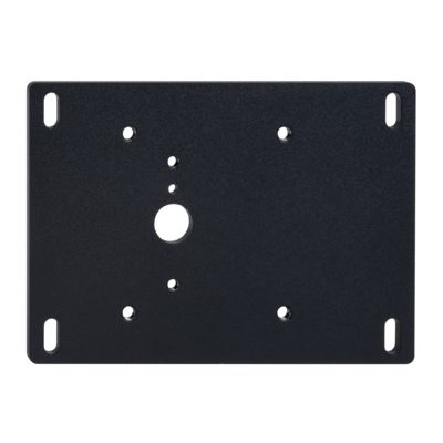
101194218 PIASTRA DI MONTAGGIO MP AZ/AZM200-B30
- Piastra di montaggio per un'installazione facile e veloce
- Metallo, verniciato a polvere
- Adatto per porte con cerniera a destra e a sinistra
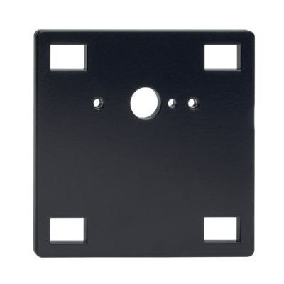
101194224 PIASTRA DI MONTAGGIO MP AZ/AZM200-P1
- Piastra di montaggio per un'installazione facile e veloce
- Metallo, verniciato a polvere
- Adatto per porte con cerniera a destra e a sinistra
101185694 PIASTRA DI MONTAGGIO MP AZ/AZM200-P20
- Piastra di montaggio per un'installazione facile e veloce
- Metallo, verniciato a polvere
- Adatto per porte con cerniera a destra e a sinistra
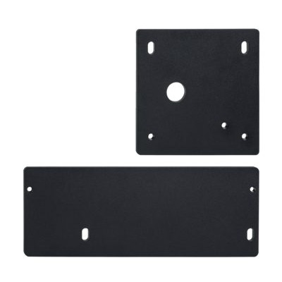
101214126 PIASTRE DI MONTAGGIO KPL. MP BDF 200
- Piastra di montaggio per un'installazione facile e veloce
- Metallo, verniciato a polvere
- Adatto per porte con cerniera a destra e a sinistra

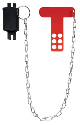
101194438 PINZA DI BLOCCAGGIO SZ 200
- Pinza di bloccaggio con 5 fori
- Adatto per montaggio all"interno ed all"esterno del area di pericolo
- Per la protezione da chiusura involontaria, per es. durante lavori di montaggio
- Per impianti controllabile difficilmente
- Impedisce l'azionamento dell'interruttore

101196397 PINZA DI BLOCCAGGIO SZ 200-1
- Pinza di bloccaggio con 6 fori
- Adatto per montaggio all"interno ed all"esterno del area di pericolo
- Per la protezione da chiusura involontaria, per es. durante lavori di montaggio
- Per impianti controllabile difficilmente
- Impedisce l'azionamento dell'interruttore
103051655 SZ201-1
- Adatto per montaggio all"interno ed all"esterno del area di pericolo
- Per la protezione da chiusura involontaria, per es. durante lavori di montaggio
- Per impianti controllabile difficilmente
- Impedisce l'azionamento dell'interruttore
- Pinza di bloccaggio con 6 fori

103009970 SRB-E-201LC
- Morsetti a vite ad innesto con codifica
- STOP 0 funzione
- 1 oder 2 -canale di controllo
- Pulsante di avvio / Auto-start
- 2 Uscite di sicurezza 2 A
- 1 Uscite di segnalazione

103007672 SRB-E-301ST
- Morsetti a vite ad innesto con codifica
- STOP 0 funzione
- 1 oder 2 -canale di controllo
- Pulsante di avvio / Auto-start
- 1 Contatto ausiliario
- 3 contatti di sicurezza

103009973 SRB-E-204ST
- Morsetti a vite ad innesto con codifica
- STOP 0 funzione
- Sorveglianza di 4 sensori
- Pulsante di avvio / Auto-start
- 2 x uscite di sicurezza a transistor
- 4 Uscite di segnalazione
Table of Contents
- 1 About this document
- 1.1 Function
- 1.2 Target group of the operating instructions: authorised qualified personnel
- 1.3 Explanation of the symbols used
- 1.4 Appropriate use
- 1.5 General safety instructions
- 1.6 Warning about misuse
- 1.7 Exclusion of liability
- 2 Product description
- 2.1 Ordering code
- 2.2 Special versions
- 2.3 Purpose
- 2.4 Technical Data
- 3 Mounting
- 3.1 General mounting instructions
- 3.2 Dimensions
- 4 Electrical connection
- 4.1 General information for electrical connection
- 4.3 Requirements for the connected safety-monitoring module
- 4.4 Serial diagnostic -SD
- 4.5 Wiring configuration and connector accessories
- 4.6 Wiring examples for series-wiring
- 5 Actuator teaching / actuator detection
- 6 Active principle and diagnostic functions
- 6.1 Mode of operation of the safety outputs
- 6.2 Diagnostic-LEDs
- 6.3 Solenoid interlock with conventional diagnostic output
- 6.4 Safety switch with serial diagnostic function SD
- 7 Set-up and maintenance
- 8 Disassembly and disposal
- 8.1 Disassembly
- 8.2 Disposal
- 9 Appendix – Special versions
1 About this document
1.1 Function
This document provides all the information you need for the mounting, set-up and commissioning to ensure the safe operation and disassembly of the switchgear. The operating instructions enclosed with the device must always be kept in a legible condition and accessible.
1.2 Target group of the operating instructions: authorised qualified personnel
All operations described in the operating instructions manual must be carried out by trained specialist personnel, authorised by the plant operator only.
Please make sure that you have read and understood these operating instructions and that you know all applicable legislations regarding occupational safety and accident prevention prior to installation and putting the component into operation.
The machine builder must carefully select the harmonised standards to be complied with as well as other technical specifications for the selection, mounting and integration of the components.
1.3 Explanation of the symbols used
- Information, hint, note: This symbol is used for identifying useful additional information.
- Caution: Failure to comply with this warning notice could lead to failures or malfunctions.
Warning: Failure to comply with this warning notice could lead to physical injury and/or damage to the machine.
1.4 Appropriate use
The Schmersal range of products is not intended for private consumers.
The products described in these operating instructions are developed to execute safety-related functions as part of an entire plant or machine. It is the responsibility of the manufacturer of a machine or plant to ensure the correct functionality of the entire machine or plant.
The safety switchgear must be exclusively used in accordance with the versions listed below or for the applications authorised by the manufacturer. Detailed information regarding the range of applications can be found in the chapter "Product description".
1.5 General safety instructions
The user must observe the safety instructions in this operating instructions manual, the country specific installation standards as well as all prevailing safety regulations and accident prevention rules.
- Further technical information can be found in the Schmersal catalogues or in the online catalogue on the Internet: products.schmersal.com.
The information contained in this operating instructions manual is provided without liability and is subject to technical modifications.
There are no residual risks, provided that the safety instructions as well as the instructions regarding mounting, commissioning, operation and maintenance are observed.
1.6 Warning about misuse
- In case of inadequate or improper use or manipulations of the component, personal hazards or damage to machinery or plant components cannot be excluded.
1.7 Exclusion of liability
We shall accept no liability for damages and malfunctions resulting from defective mounting or failure to comply with the operating instructions manual. The manufacturer shall accept no liability for damages resulting from the use of unauthorised spare parts or accessories.
For safety reasons, invasive work on the device as well as arbitrary repairs, conversions and modifications to the device are strictly forbidden, the manufacturer shall accept no liability for damages resulting from such invasive work, arbitrary repairs, conversions and/or modifications to the device.
2 Product description
2.1 Ordering code
| Product type description: AZ201(1)-T-(2) |
| (1) | |
| SK | Screw connection |
| CC | Cage clamp |
| ST1 | Connector M23 x 1, 8+1 pole |
| ST2 | Connector M12 x 1, 8 pole |
| (2) | |
| 1P2P | 1 serial diagnostic output and 2 p-type safety outputs |
| SD2P | serial diagnostic output and 2 p-type safety outputs |
| Actuator | suitable for |
|---|---|
| AZ/AZM201-B1-... | Sliding safety guards |
| AZ/AZM201-B30-... | Hinged safety guards |
| AZ/AZM201-B40-... | Hinged-doors with overlapping folds |
- Only if the information described in this operating instructions manual are followed correctly, the safety function and therefore the compliance with the Machinery Directive is maintained.
2.2 Special versions
For special versions, which are not listed in the ordering code, these specifications apply accordingly, provided that they correspond to the standard version.
- Special information or information deviating from the standard on special versions can be found in the concluding chapter "Appendix – Special versions".
2.3 Purpose
The non-contact, electronic safety switchgear is designed for application in safety circuits and is used for monitoring the position and locking of movable safety guards.
The safety switchgears are classified according to ISO 14119 as type 4 interlocking devices. Designs with individual coding are classified as highly coded.
The safety function consists of safely switching off the safety outputs when the safety guard is opened and maintaining the safe switched off condition of the safety outputs for as long as the safety guard is open.
Series-wiring can be set up. In the case of a series connection, the risk time remains unchanged and the reaction time increases by the sum of the reaction time of the inputs per additional unit specified in the technical data. The quantity of devices is only limited by the cable drops and the external cable fuse protection, according to the technical data. Up to 31 device variants with serial diagnostics can be wired in series.
- The user must evaluate and design the safety chain in accordance with the relevant standards and the required safety level. If multiple safety sensors are involved in the same safety function, the PFH values of the individual components must be added.
- The entire concept of the control system, in which the safety component is integrated, must be validated to the relevant standards.
2.4 Technical Data
Omologazioni - Prescrizioni
| Certificazioni |
TÜV cULus FCC IC ANATEL |
Dati generali
| Prescrizioni |
EN ISO 13849-1 EN ISO 14119 EN IEC 60947-5-3 EN IEC 61508 |
|
| informazioni generali |
Codifica individuale, Teach-in ripetibile |
|
| Livello di codifica secondo EN ISO 14119 |
alto |
|
| principio d'azione |
RFID, 125 kHz |
|
| Transmitter output RFID, maximum |
-6 dB/m |
|
| Materiale della custodia |
materiale sintetico, termoplastica rinforzata con fibra di vetro |
|
| Tempo di rischio, massimo |
200 ms |
|
|
100 ms |
|
|
0,5 ms |
|
| Peso lordo |
403 g |
Dati generali - Caratteristiche
| Riconoscimento cortocircuiti |
Sì |
| Riconoscimento di corto circuito |
Sì |
| Azionamento in serie |
Sì |
| Funzioni di sicurezza |
Sì |
| Display integrato, stato |
Sì |
| quantità di contatti di sicurezza |
2 |
Osservazioni per la sicurezza
| Norma, Prescrizioni |
EN ISO 13849-1 EN IEC 61508 |
| Performance Level, fino a |
e |
| Categoria secondo EN ISO 13849 |
4 |
| Valore PFH |
1,90 x 10⁻⁹ /h |
| Valore PFD |
1,60 x 10⁻⁴ |
Safety Integrity Level (SIL), idoneo per applicazioni in |
3 |
| Durata di utilizzo |
20 Anno(i) |
Dati meccanici
| Durata meccanica, minimo |
1.000.000 manovre |
| Forza di ritenuta |
30 N |
| Velocità di azionamento, massima |
0,2 m/s |
| Versione delle viti di fissaggio |
2x M6 |
| Tightening torque of the fastening screws for the housing cover, minimum |
0,7 Nm |
| Tightening torque of the fastening screws for the housing cover, maximum |
1 Nm |
| Note |
Torx T10 |
Dati meccanici - Distanze di commutazione secondo EN IEC 60947-5-3
| Campo, distanza di commutazione sicura "ON" |
4 mm |
| Distanza di commutazione sicura "OFF" |
30 mm |
| Isteresi (Distanza di commutazion), massimo |
1,5 mm |
| Precisione di ripetizione R |
0,5 mm |
Dati meccanici - Tecnologia di collegamento
| Length of sensor chain, maximum |
200 m |
| Note (length of the sensor chain) |
Cable length and cross-section change the voltage drop dependiing on the output current |
| Note (series-wiring) |
Unlimited number of devices, oberserve external line fusing, max. 31 devices in case of serial diagnostic SD |
| Connettore di collegamento |
Collegamento a vite M20 x 1.5 |
| Sezione di collegamento, minima |
0,25 mm² |
| Sezione di collegamento, massimo |
1,5 mm² |
| Osservazioni (Sezione di collegamento) |
Tutte le indicazioni sulla sezione del cavo includono le bussole del conduttore. |
| Sezione conduttore, minimo |
23 AWG |
| Sezione conduttore, massimo |
15 AWG |
| Wire cross-section |
23 ... 15 AWG |
| Allowed type of cable |
solid single-wire solid multi-wire flexible |
Dati meccanici - Dimensioni
| lunghezza del sensore |
50 mm |
| larghezza del sensore |
40 mm |
| altezza del sensore |
220 mm |
Condizioni ambientali
| Grado di protezione |
IP67 IP66 |
| Ambient temperature |
-25 ... +70 °C |
| Storage and transport temperature |
-25 ... +85 °C |
| Umidità relativa, massima |
93 % |
| Osservazioni (umidità relativa) |
non condensante non gela |
| Resistenza alle vibrazioni secondo EN 60068-2-6 |
10 … 150 Hz, ampiezza 0,35 mm |
| resistenza a urti |
30 g / 11 ms |
| Classe di protezione |
III |
| Altitudine di installazione ammissibile s.l.m., massima |
2.000 m |
Condizioni ambientali - Valori di isolamento
| Tensione d'isolamento nominale |
32 VDC |
| Resistenza alla tensione impulsiva nominale |
0,8 kV |
| Categoria di sovratensione |
III |
| Grado di inquinamento secondo VDE 0100 |
3 |
Dati elettrici
| Operating voltage |
24 VDC -15 % / +10 % |
| No-load supply current I0, typical |
50 mA |
| Rated operating voltage |
24 VDC |
| Corrente di funzionamento |
700 mA |
| Corrente nominale di cortocircuito condizionata secondo EN 60947-5-1 |
100 A |
| External wire and device fuse rating |
4A gG |
| Ritardo di disponibilità, massimo |
4.000 ms |
| Frequenza di commutaz, massimo |
1 Hz |
Dati elettrici - Ingressi digitali sicuri
| Denominazione, Ingressi di sicurezza |
X1 and X2 |
| Soglie di commutazione |
−3 V … 5 V (Low) 15 V … 30 V (High) |
| Assorbimento di corrente a 24 V |
5 mA |
| Test pulse duration, maximum |
1 ms |
| Test pulse interval, minimum |
100 ms |
| Classificazione ZVEI CB24I, Sink |
C1 |
| Classificazione ZVEI CB24I, Fonte |
C1 C2 C3 |
Dati elettrici - Uscite digitali sicure
| Denominazione, Uscite di sicurezza |
Y1 e Y2 |
| Corrente d'esercizio nominale (uscite di sicurezza) |
250 mA |
| Versione |
resistente a cortocircuito, con commutazione p |
| Caduta di tensione Ud, massimo |
4 V |
| corrente residua |
0,5 mA |
| Tensione, Categoria d'utilizzo DC-13 |
24 VDC |
| Corrente, categoria d'utilizzo DC-13 |
0,25 A |
| Test pulse interval, typical |
1000 ms |
| Test pulse duration, maximum |
0,5 ms |
| Classificazione ZVEI CB24I, Fonte |
C2 |
| Classificazione ZVEI CB24I, Sink |
C1 C2 |
Dati elettrici - Uscita di diagnosi
| Designazione, Uscite diagnostiche |
OUT |
| Corrente di funzionamento |
50 mA |
| Versione |
resistente a cortocircuito, con commutazione p |
| Caduta di tensione Ud, massimo |
4 V |
| Tensione, Categoria d'utilizzo DC-13 |
24 VDC |
| Corrente, categoria d'utilizzo DC-13 |
0,05 A |
Segnalazione di stato
| Osservazioni (Indicatori di stato a LED) |
Stato operativo: LED giallo Errore malfunzionamento: LED rosso Tensione di alimentazione UB: LED verde |
UL notice
Use isolated power supply only. For use in NFPA 79 Applications only. Adapters providing field wiring means are available from the manufacturer. Refer to manufacturers information.
FCC/IC - Note
This device complies with Part 15 of the FCC Rules and contains licence-exempt transmitter/receivers that are compliant with ISED (Innovation, Science and Economic Development) Canada licence-exempt RSS standard(s).
Operation is subject to the following two conditions:
(1) This device may not cause harmful interference signals, and
(2) This device must be able to tolerate interference signals. These also include interference signals that could cause the device to function improperly.
This device complies with the nerve stimulation limits (ISED SPR-002) when operated at a minimum distance of 100 mm. Changes or modifications not expressly approved by K.A. Schmersal GmbH & Co. KG could void the user's authority to operate the equipment.
The licence-free transmitter/receiver contained in this device satisfies the requirements of the "Radio Standards Specification" of the Innovation, Science and Economic Development Canada (ISED) authority that apply to licence-free radio equipment. Operation is permissible under the following two conditions:
(1) The device must not create disturbances.
(2) The device must tolerate received radio frequency interference, even if this could impair its functionality.
This device complies with the nerve stimulation limits (ISED CNR-102) when operated at a minimum distance of 100 mm.
In the event of changes or modifications that have not been expressly approved by K.A. Schmersal GmbH & Co. KG, the user's authorisation to use the device may become ineffective.
| 20941-22-14519 | Este equipamento nao tem direito àprotecao contra interferência prejudicial e nao pode causar interferencia em sistemas devidamente autorizados. Para maiores informacores consultar: www.gov.br/anatel |
3 Mounting
3.1 General mounting instructions
- Please observe the relevant requirements of the standards ISO 12100, ISO 14119 and ISO 14120.
For fitting the safety switch and the actuator, two mounting holes for M6 screws with washers (washers included in delivery) are provided. The safety switch must not be used as end stop. Any position is possible. The mounting position however must be chosen so that the ingress of dirt and soiling in the used opening is avoided. The unused actuator opening must be sealed by means of the dust-proof flap (included in delivery).
Minimum distance between two safety switchgear
as well as to other systems with same frequency (125 kHz): 100 mm.

Mounting of the actuators
Refer to the mounting instructions manual for the corresponding actuator.
- The actuator must be permanently fitted to the safety guards and protected against displacement by suitable measures (tamperproof screws, gluing, drilling of the screw heads).
3.2 Dimensions
All measurements in mm.

Legend
B: Active RFID area
- Metal parts and magnetic fields in the lateral RFID area of the safety switchgear and the actuator can influence the switching distance or lead to malfunctions.
4 Electrical connection
4.1 General information for electrical connection
- The electrical connection may only be carried out by authorised personnel in a de-energised condition.
The power supply must have protection against permanent overvoltage. Supply units according to EN 60204-1 is recommended.
The required electrical cable fuse protection must be integrated in the installation.
The safety outputs can be integrated into the safety circuit of the control system.
- The fitted 24V, X1, X2 bridge is included in the delivery of …-1P2P and …-SD2P.
The cable entry is realised by a metric M20 gland. This gland must be dimensioned by the user so that it is suitable for the cable used. A cable gland with strain relief and suitable IP degree of protection must be used.
Settle length x of the conductor:
- on screw terminals (SK): 8 mm
- on cage clamps (CC) of type s, r or f: 7.5 mm

4.3 Requirements for the connected safety-monitoring module
Dual-channel safety input, suitable for 2 p-type semi-conductor outputs (OSSD)
- Safety controller configuration
If the safety switchgear is connected to electronic safety-monitoring modules, we recommend that you set a discrepancy time of at least 100 ms. The safety inputs of the safety-monitoring module must be able blanking a test impulse of approx. 1 ms. The safety-monitoring module does not need to have a cross-wire short monitoring function, if necessary, the cross-wire short monitoring function must be disabled.
- Information for the selection of suitable safety-monitoring modules can be found in the Schmersal catalogues or in the online catalogue on the Internet: products.schmersal.com
4.4 Serial diagnostic -SD
- Accessories for the series-wiring
For convenient wiring and series-wiring of SD components, the SD junction boxes PFB-SD-4M12-SD (variant for the field) and PDM-SD-4CC-SD (variant for control cabinet on carrier rail) are available along with additional comprehensive accessories. Detailed information is available on the Internet, products.schmersal.com.
- On wiring SD devices, please pay attention to the voltage drop on the cables and the current carrying capacity of the individual components.
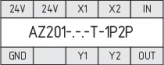
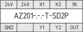
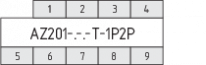
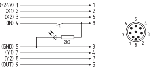
4.5 Wiring configuration and connector accessories
| Function safety switchgear | Pin configuration of the connector ST2, M12, 8-pole | Configuration of the removable terminal blocks | Colour codes of the Schmersal connector plugs to DIN 47100 | Poss. colour code of other commercially available connector plugs according to EN 60947-5-2 | ||
|---|---|---|---|---|---|---|
| With conventional diagnostic output | with serial diagnostic function |  | ||||
| 24V | Ue | 1 | 1 | WH | BN | |
| X1 | Safety input 1 | 2 | 2 | BN | WH | |
| GND | GND | 3 | 5 | GN | BU | |
| Y1 | Safety output 1 | 4 | 7 | YE | BK | |
| OUT | Diagnostic output | SD output | 5 | 9 | GY | GY |
| X2 | Safety input 2 | 6 | 3 | PK | PK | |
| Y2 | Safety output 2 | 7 | 8 | BU | VT | |
| IN | without function | SD input | 8 | 4 | RD | OR |
| without function | - | 6 | ||||
| View Terminal block for ordering suffix -SK or -CC | View Version with removable terminal blocks | |
|---|---|---|
 |  |  |
| Connecting cables with coupling (female) IP67 / IP69, M12, 8-pole - 8 x 0.25 mm² to DIN 47100 | |
|---|---|
| Cable length | Ordering code |
| 2,5 m | 103011415 |
| 5,0 m | 103007358 |
| 10,0 m | 103007359 |
| 15,0 m | 103011414 |
Further versions in other lengths and with angled cable exit are available upon request.
4.6 Wiring examples for series-wiring
Series-wiring can be set up. In the case of a series connection, the risk time remains unchanged and the reaction time increases by the sum of the reaction time of the inputs per additional unit specified in the technical data. The quantity of devices is only limited by the cable drops and the external cable fuse protection, according to the technical data. Series-wiring of up to 31 AZ201 … SD components with serial diagnostics is possible.
The application examples shown are suggestions. They however do not release the user from carefully checking whether the switchgear and its set-up are suitable for the individual application. The application examples shown are suggestions.
Wiring example 1: Series wiring AZ201 with conventional diagnostic output.
In the series wiring, the 24V-X1-X2 bridge must be removed from all components up to the last component. The voltage is supplied at both safety inputs of the terminal safety component of the chain (considered from the safety-monitoring module). The safety outputs of the first safety component are wired to the safety-monitoring module.

Y1 and Y2 = Safety outputs → Safety monitoring module
Wiring example 2: Series-wiring of the AZ201 with serial diagnostic function (max. 31 components in series)
In devices with the serial diagnostics function (ordering suffix -SD), the serial diagnostics connections are wired in series and connected to a SD-Gateway for evaluation purposes. The safety outputs of the first safety component are wired to the safety-monitoring module. The serial Diagnostic Gateway is connected to the serial diagnostic input of the first safety component.
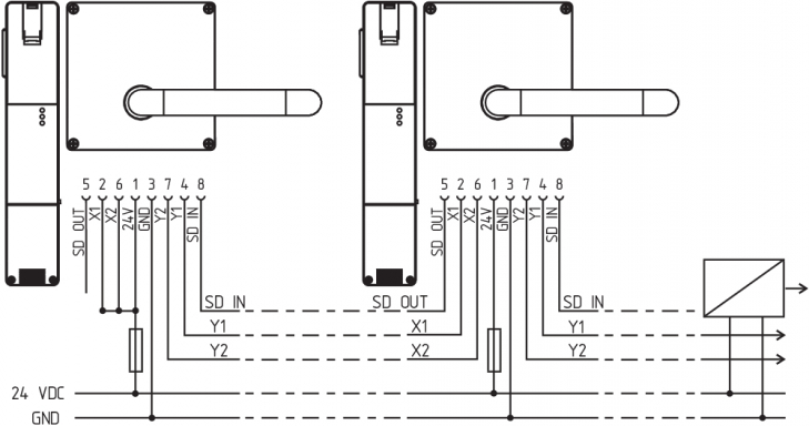
Y1 and Y2 = Safety outputs → Safety monitoring module
SD-IN → Gateway → Field bus
5 Actuator teaching / actuator detection
Safety switches with standard coding are ready to use upon delivery.
Individually coded safety switches and actuators will require the following "teach-in" procedure:
- Switch the safety switch's voltage supply off and back on.
- Introduce the actuator in the detection range. Teach-in is signalled on the safety switch, the green LED is switched off, the red LED illuminates and the yellow LED flashes (1 Hz).
- After 10 seconds, brief cyclic yellow flashes (3 Hz) request the switch-off of the operating voltage of the safety switch. (If the voltage. is not switched off within 5 minutes, the safety switch cancels the "teach-in" procedure and signals a false actuator by 5 red flashes).
- Once the operating voltage is switched back on, the actuator must be detected once more in order to activate the actuator code that has been taught in. In this way, the activated code is definitively saved!
For ordering suffix -I1, the executed allocation of safety switchgear and actuator is irreversible.
For ordering suffix -I2, the "teach-in" procedure for a new actuator can be repeated an unlimited number of times. When a new actuator is taught, the code, which was applicable until that moment, becomes invalid. Subsequent to that, an enabling inhibit will be active for ten minutes, thus providing for an increased protection against tampering. The green LED will flash until the expiration of the time of the enabling inhibit and the detection of the new actuator. In case of power failure during the lapse of time, the 10-minutes tampering protection time will restart.
6 Active principle and diagnostic functions
6.1 Mode of operation of the safety outputs
The opening of the safety guard causes the safety outputs to be disabled within the risk time.
6.2 Diagnostic-LEDs
The safety switchgear signals the operational state as well as errors through three coloured LEDs installed on the front side of the device.
| green (Power) | Supply voltage on |
| yellow (Status) | Operating condition |
| red (Fault) | Error (see table 2: Error messages / flash codes red diagnostic LED) |
6.3 Solenoid interlock with conventional diagnostic output
The short-circuit proof diagnostic output OUT can be used for central visualisation or control tasks, e.g. in a PLC.
The closed condition of the safety guard and the inserted condition of the actuator is indicated by means of a 24V signal.
The diagnostic output is not a safety-related output.
Error
Errors which no longer guarantee the function of the safety switchgear (internal errors) cause the safety outputs to be disabled within the duration of risk. After fault rectification, the error message is reset by opening and re-closing the corresponding safety guard.
- Automatic, electronic locking takes place if more than one fault is detected at the safety outputs or a cross circuit is detected between Y1 and Y2. This means that normal fault acknowledgement is no longer possible. To reset this type of interlocking, the safety switch must be isolated from the power supply after elimination of the error causes.
Fault warning
A fault that does not immediately endanger the safety function of the safety switchgear (e.g. too high ambient temperature, safety output at external potential, cross-circuit) leads to delayed shutdown (see Table 2). This signal combination, diagnostic output disabled and safety channels still enabled, can be used to stop the production process in a controlled manner. An error warning is deleted when the cause of error is eliminated. If the fault warning remains on for 30 minutes, the safety outputs are also switched off (red LED flashes, see Table 2).
| Table 1: Diagnostic information of the safety switchgear | |||||
|---|---|---|---|---|---|
| System condition | LED | Safety outputs Y1, Y2 | Diagnostic output OUT -1P2P | ||
| green | red | yellow | |||
| Door open | On | Off | Off | 0 V | 0 V |
| Door closed, actuator not inserted | On | Off | Off | 0 V | 0 V |
| Door closed, actuator inserted | On | Off | On | 24 V | 24 V |
| Error warning1), actuator inserted, shutdown approaching | On | Flashes 2) | On | 24 V1) | 0 V |
| Error | On | Flashes 2) | Off | 0 V | 0 V |
| Additionally for variant I1/I2: | |||||
| Teach-in procedure actuator started | Off | On | Flashes | 0 V | 0 V |
| Only I2: teach-in procedure actuator (release block) | Flashes | Off | Off | 0 V | 0 V |
1) after 30 min. disabling due to fault 2) see flash code | |||||
| Table 2: Error messages / flash codes red diagnostic LED | |||
|---|---|---|---|
| Flash codes | Designation | Autonomous switch-off after | Error cause |
| 1 flash pulse | Error (warning) at output Y1 | 30 min | Fault in output test or voltage at output Y1, although the output is disabled. |
| 2 flash pulses | Error (warning) at output Y2 | 30 min | Fault in output test or voltage at output Y2, although the output is disabled. |
| 3 flash pulses | Error (warning) cross-wire short | 30 min | Cross-wire short between the output cables or fault at both outputs |
| 4 flash pulses | Error (warning) temperature too high | 30 min | The temperature measurement reveals an internal temperature that is too high |
| 5 flash pulses | Actuator fault | 0 min | Incorrect or defective actuator |
| 6 flash pulses | Error actuator combination | 0 min | An invalid combination of actuators was detected (blocking bolt detection or tamper attempt). |
| Continuous red signal | Internal fault / overvoltage or undervoltage fault | 0 min | Device defective / supply voltage not within specifications |
6.4 Safety switch with serial diagnostic function SD
Safety switches with serial diagnostic cable have a serial input and output cable instead of the conventional diagnostic output. If safety switches are wired in series, the diagnostic data is transmitted through the series-wiring of the inputs and outputs.
Max. 31 safety switches can be wired in series. For the evaluation of the serial diagnostics line either the PROFIBUS-Gateway SD-I-DP-V0-2 or the Universal-Gateway SD-I-U-... are used. This serial diagnostic interface is integrated as slave in an existing field bus system. In this way, the diagnostic signals can be evaluated by means of a PLC.
The necessary software for the integration of the SD-Gateway is available for download at products.schmersal.com.
The response data and the diagnostic data are automatically and permanently written in an input byte of the PLC for each safety switch in the series-wired chain. The request data for each safety switch are transmitted to the component through an output byte of the PLC. In case of a communication error between the field bus gateway and the safety switch, the switching condition of the safety switch is maintained.
Error
Errors which no longer guarantee the function of the safety switchgear (internal errors) cause the safety outputs to be disabled within the duration of risk. The fault is reset, when the cause is eliminated and bit 7 of the request byte changes from 1 to 0 or the safety guard is opened. Faults at the safety outputs are only deleted upon the next release, as the fault rectification cannot be detected sooner.
- Automatic, electronic locking takes place if more than one fault is detected at the safety outputs or a cross circuit is detected between Y1 and Y2. This means that normal fault acknowledgement is no longer possible. To reset this type of interlocking, the safety switch must be isolated from the power supply after elimination of the error causes.
Error warning
A fault that does not immediately endanger the safety function of the safety switchgear (e.g. too high ambient temperature, safety output at external potential, cross-circuit) leads to delayed shutdown. This signal combination, diagnostic output disabled and safety channels still enabled, can be used to stop the production process in a controlled manner.
An error warning is deleted when the cause of error is eliminated.
If the fault warning remains on for 30 minutes, the safety outputs are also switched off (red LED flashes).
Diagnostic error (warning)
If an error (warning) is signalled in the response byte, detailed fault information can be read out.
| Table 3: I/O data and diagnostic data (The described condition is reached, when Bit = 1) | ||||
|---|---|---|---|---|
| Bit n° | Request byte | Response byte | Diagnostic error warning | Diagnostic error |
| Bit 0: | --- | Safety output activated | Error output Y1 | Error output Y1 |
| Bit 1: | --- | Actuator detected | Error output Y2 | Error output Y2 |
| Bit 2: | --- | --- | Cross-wire short | Cross-wire short |
| Bit 3: | --- | --- | Temperature too high | Temperature too high |
| Bit 4: | --- | Input condition X1 and X2 | --- | Incorrect or defective actuator |
| Bit 5: | --- | Guard door detected | Internal device error | Internal device error |
| Bit 6: | --- | Error warning 1) | Communication error between the field bus Gateway and the safety switchgear | --- |
| Bit 7: | Error reset | Error (enabling path switched off) | --- | --- |
| 1) after 30 min -> fault | ||||
7 Set-up and maintenance
The safety function of the safety components must be tested. In the case of correct installation and adequate use, the safety switchgear features maintenance-free functionality. A regular visual inspection and functional test, including the following steps, is recommended:
- Check fixation of the safety switch and the actuator.
- Check max. axial misalignment of actuator and safety switch.
- Fitting and integrity of the cable connections.
- Check the switch enclosure for damages
- Remove particles of dust and soiling.
- Adequate measures must be taken to ensure protection against tampering either to prevent tampering of the safety guard, for instance by means of replacement actuators.
- Damaged or defective components must be replaced.
8 Disassembly and disposal
8.1 Disassembly
The safety switchgear must be disassembled in a de-energised condition only.
8.2 Disposal
- The safety switchgear must be disposed of in an appropriate manner in accordance with the national prescriptions and legislations.
9 Appendix – Special versions
Special version -2965-1

| Connecting cables with coupling (female) IP67, M23, 12 pole - 12 x 0.75 mm² | |
|---|---|
| Cable length | Ordering code |
| 5.0 m | 101208520 |
| 10.0 m | 103007354 |
| 20.0 m | 101214418 |
Special version -2965-2

| Connecting cables with coupling (female) IP67, M23, 8+1 pole - 9 x 0.75 mm² | |
|---|---|
| Cable length | Ordering code |
| 5.0 m | 101209959 |
| 10.0 m | 101209958 |
| 15.0 m | 103001384 |
| Connecting cables with coupling (female) IP67, M12, 8 pole - 8 x 0.25 mm² | |
|---|---|
| Cable length | Ordering code |
| 2.5 m | 103011415 |
| 5.0 m | 103007358 |
| 10.0 m | 103007359 |
Special version -2965-3
| Connecting cables with coupling (female) IP67, M12, 8 pole - 8 x 0.25 mm² | |
|---|---|
| Cable length | Ordering code |
| 2.5 m | 103011415 |
| 5.0 m | 103007358 |
| 10.0 m | 103007359 |
| EU-Konformitätserklärung |  |
| Original | K.A. Schmersal GmbH & Co. KG Möddinghofe 30 42279 Wuppertal Germany Internet: www.schmersal.com |
| Erklärung: | Hiermit erklären wir, dass die nachfolgend aufgeführten Bauteile aufgrund der Konzipierung und Bauart den Anforderungen der unten angeführten Europäischen Richtlinien entsprechen. |
| Bezeichnung des Bauteils: | AZ201 |
| Typ: | siehe Typenschlüssel |
| Beschreibung des Bauteils: | Sicherheitsschalter für Sicherheitsfunktionen |
| Einschlägige Richtlinien: | Maschinenrichtlinie | 2006/42/EG |
| RED-Richtlinie | 2014/53/EU | |
| RoHS-Richtlinie | 2011/65/EU |
| Angewandte Normen: | EN 60947-5-3:2013 ISO 14119:2013 EN 300 330 V2.1.1:2017 EN ISO 13849-1:2015 EN 61508 Teile 1-7:2010 |
| Benannte Stelle der Baumusterprüfung: | TÜV Rheinland Industrie Service GmbH Am Grauen Stein, 51105 Köln Kenn-Nr.: 0035 |
| EG-Baumusterprüfbescheinigung: | 01/205/5608.00/17 |
| Bevollmächtigter für die Zusammenstellung der technischen Unterlagen: | Oliver Wacker Möddinghofe 30 42279 Wuppertal |
| Ort und Datum der Ausstellung: | Wuppertal, 21. Mai 2021 |
 |
| Rechtsverbindliche Unterschrift Philip Schmersal Geschäftsführer |
Schmersal Italia S.r.l., Via Molino Vecchio, 206, 25010 Borgosatollo (BS)
I dettagli e i dati qui riportati sono stati attentamente verificati. Le immagini possono differire dagli originali. Altri dati tecnici possono essere trovati nei manuali. Salvo modifiche tecniche o errori.
Generato il 24/04/2024, 15:58