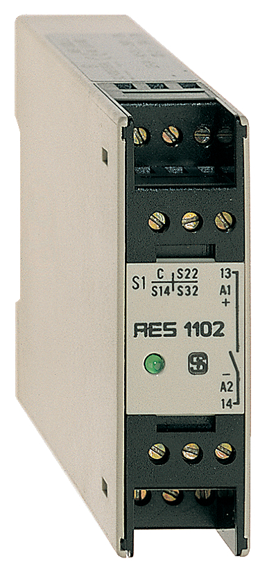
AES 1102.3 24 VAC
- Monitoring of BNS range magnetic safety sensors
- 1 safety contact, STOP 0
Ordering data
| Note (Delivery capacity) |
Not available! |
| Product type description |
AES 1102.3 24 VAC |
| Article number (order number) |
101128797 |
| EAN (European Article Number) |
4030661278858 |
| eCl@ss number, version 12.0 |
27-37-18-19 |
| eCl@ss number, version 11.0 |
27-37-18-19 |
| eCl@ss number, version 9.0 |
27-37-18-19 |
| ETIM number, version 7.0 |
EC001449 |
| ETIM number, version 6.0 |
EC001449 |
Approvals - Standards
| Certificates |
cULus |
General data
| Standards |
BG-GS-ET-14 BG-GS-ET-20 EN IEC 62061 EN ISO 13849-1 EN IEC 60947-5-1 EN IEC 60947-5-3 EN IEC 60947-5-5 EN IEC 60204-1 EN IEC 60947-1 |
| Climatic stress |
EN 60068-2-3 BG-GS-ET-14 |
| Housing material |
グラスファイバー強化熱可塑性樹脂、換気口付き |
| Gross weight |
124 g |
General data - Features
| Wire breakage detection |
Yes |
| Automatic reset function |
Yes |
| Reset after disconnection of supply voltage |
Yes |
| Integral system diagnostics, status |
Yes |
| Number of LEDs |
1 |
| Number of normally closed (NC) |
4 |
| Number of normally open (NO) |
2 |
| Number of safety contacts |
1 |
| Safety classification |
| Vorschriften |
EN ISO 13849-1 EN IEC 61508 |
| Stop-Category |
0 |
| Safety classification - Relay outputs |
| Performance Level, up to |
c |
| Category |
1 |
| PFH value |
1.14 x 10⁻⁶ /h |
| Notice |
for max. 50,000 switching cycles/year and max. 80% contact load |
| Safety Integrity Level (SIL), suitable for applications in |
1 |
| Mission time |
20 Year(s) |
Mechanical data
| Mechanical life, minimum |
3,000,000 Operations |
| Mounting |
EN 60715に基づくDINレールにワンタッチ取り付け |
Mechanical data - Connection technique
| Terminal designations |
IEC/EN 60947-1 |
| Termination |
単線 / 撚線 ネジ端子 M20 x 1.5 |
| Cable section, maximum |
2.5 mm² |
| Tightening torque of Clips |
0.6 Nm |
Mechanical data - Dimensions
| Width |
22.5 mm |
| Height |
75 mm |
| Depth |
110 mm |
Ambient conditions
| Degree of protection of the enclosure |
IP40 |
| Degree of protection of the mounting space |
IP54 |
| Degree of protection of clips or terminals |
IP20 |
| Ambient temperature |
+0 ... +55 °C |
| Storage and transport temperature |
-25 ... +70 °C |
| Resistance to vibrations |
10 ~ 55 Hz、振幅 0.35 mm、± 15 % |
| Restistance to shock |
30 g / 11 ms |
Ambient conditions - Insulation values
| Rated impulse withstand voltage Uimp |
4 kV |
| Overvoltage category |
III |
| Degree of pollution |
2 |
Electrical data
| Frequency range |
50 Hz 60 Hz |
| Thermal test current |
4 A |
| Rated operating voltage |
24 VAC |
| Rated AC voltage for controls, 50 Hz, minimum |
20.4 VAC |
| Rated control voltage at AC 50 Hz, maximum |
26.4 VAC |
| Rated AC voltage for controls, 60 Hz, minimum |
20.4 VAC |
| Rated control voltage at AC 60 Hz, maximum |
26.4 VAC |
| Electrical power consumption |
2.4 W |
| Contact resistance, maximum |
0.1 Ω |
| Note (Contact resistance) |
新しい状態で |
| Drop-out delay in case of power failure, typically |
80 ms |
| Drop-out delay in case of emergency, typically |
20 ms |
| Pull-in delay at automatic start, maximum, typically |
100 ms |
| Pull-in delay at RESET, typically |
20 ms |
| Material of the contacts, electrical |
AgCdO |
Electrical data - Safe relay outputs
| Voltage, Utilisation category AC-15 |
250 VAC |
| Current, Utilisation category AC-15 |
1.5 A |
| Voltage, Utilisation category DC-13 |
24 VDC |
| Current, Utilisation category DC-13 |
1 A |
| Switching capacity, minimum |
10 VDC |
| Switching capacity, minimum |
10 mA |
| Switching capacity, maximum |
250 VAC |
| Switching capacity, maximum |
8 A |
Electrical data - Digital inputs
| Conduction resistance, maximum |
40 Ω |
Electrical data - Digital Output
| Voltage, Utilisation category DC-12 |
24 VDC |
| Current, Utilisation category DC-12 |
0.1 A |
Electrical data - Relay outputs (auxiliary contacts)
| Switching capacity, maximum |
24 VDC |
| Switching capacity, maximum |
2 A |
Electrical data - Electromagnetic compatibility (EMC)
| EMC rating |
EMC-Directive |
Status indication
| Indicated operating states |
Authorised operation |
Other data
| Note (applications) |
セーフティセンサー ガードシステム |
Note
| Note (General) |
Inductive loads (e.g. contactors, relays, etc.) are to be suppressed by means of a suitable circuit. |
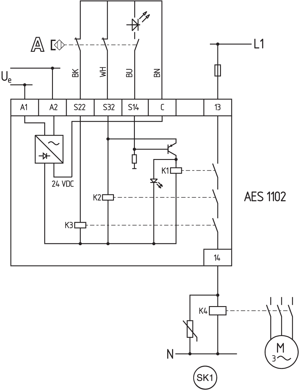
Wiring example
| Note (Wiring diagram) |
To secure one or a number of guard doors up to PL c and Category 1 Monitoring a number of guard doors using magnetic safety sensors BNS range The wiring diagram is shown with guard doors closed and in de-energised condition. |
言語フィルター
データシート
Operating instructions and Declaration of conformity
UL Certificate
Wiring example (electr. wiring)
SISTEMA-VDMA library
Adobe Readerの最新版をダウンロードしてください
Product picture (catalogue individual photo)
Wiring example
| EU Declaration of Conformity |  |
| Original | K.A. Schmersal GmbH & Co. KG Möddinghofe 30 42279 Wuppertal Germany Internet: www.schmersal.com |
| Declaration: | We hereby certify that the hereafter described components both in their basic design and construction conform to the applicable European Directives. |
| Name of the component: | AES 1102 AES 1112 |
| Type: | See ordering code |
| Description of the component: | Safety-monitoring module for non-contact safety switches and safety relay combination in connection with the BNS series magnetic safety switches |
| Relevant Directives: | Machinery Directive | 2006/42/EC |
| EMC-Directive | 2014/30/EU | |
| RoHS-Directive | 2011/65/EU |
| Applied standards: | EN 60947-5-3:2013 EN ISO 13849-1:2015 EN ISO 13849-2:2012 |
| Notified body, which approved the full quality assurance system, referred to in Appendix X, 2006/42/EC: | TÜV Rheinland Industrie Service GmbH Am Grauen Stein, 51105 Köln ID n°: 0035 |
| Person authorised for the compilation of the technical documentation: | Oliver Wacker Möddinghofe 30 42279 Wuppertal |
| Place and date of issue: | Wuppertal, December 16, 2021 |
 |
| Authorised signature Philip Schmersal Managing Director |
Schmersal India Pvt. Ltd., Plot No - G-7/1, Ranjangaon MIDC, Tal. - Shirur, Dist.- Pune 412 220
データと詳細は完全にチェックされました。画像は元の画像と異なる場合があります。技術的なデータはマニュアルで見られます。技術的に変更されたり、エラーの可能性があります。
Generated on 2025/05/02 20:42