BN 85-R
BN 85-R
Downloads
- Mounting with clamping brackets and 2 single wires
- Actuation from front
- Non-contact principle
- 1 Reed contakts
- Long life
- Actuating distance up to 40 mm depending on actuating magnet and version
- 40 mm x 35 mm x 16,5 mm
- Thermoplastic enclosure
- Reed-contact to clip-in, on-location assembly
Ordering data
| Product type description |
BN 85-R |
| Article number (order number) |
101091836 |
| EAN (European Article Number) |
4030661023472 |
| eCl@ss number, version 12.0 |
27-27-43-02 |
| eCl@ss number, version 11.0 |
27-27-01-05 |
| eCl@ss number, version 9.0 |
27-27-01-05 |
| ETIM number, version 7.0 |
EC002544 |
| ETIM number, version 6.0 |
EC002544 |
General data
| Working principle |
磁気装置 |
| Versions |
Plug-in reed contact insert and base |
| Housing construction form |
ブロック型 |
| Housing material |
グラスファイバー強化熱可塑性樹脂 |
| Gross weight |
40 g |
General data - Features
| Latching |
Yes |
| Suitable for elevators |
Yes |
| Number of snap-in contacts |
1 |
Mechanical data
| Active area |
前面 |
| Mechanical lifetime, minimum |
1,000,000,000 Operations |
| Actuation direction |
Lengthwise |
| Actuating speed, maximum |
18 m/s |
| Mounting |
clamping foot 8 mm |
Mechanical data - Switching distances
| Switching distance Sn |
2 mm … 40 mm BP 6S = 2 … 12 mm BP 8S = 2 … 10 mm BP 10S = 5 … 20 mm 2 x BP 10S = 6 … 27 mm BP 15S = 5 … 22 mm 2 x BP 15S = 7 … 28 mm BP 34S = 10 … 40 mm BP 20S = 3 ... 28 mm BP 31S = 4 ... 30 mm BP 11S = 4 ... 23 mm BP 12S = 5 ... 27 mm |
| Note (Switching distance Sn) |
Actuating distance up to 40 mm depending on actuating magnet and version. The specified switching distances are applicable for the actuation of individually mounted components without ferromagnetic influence. A change of the distance, either positive or negative, is possible due to ferromagnetic influences. The mutual interference between multiple actuating magnets must be observed. |
| Note (switching distance) |
All switching distances in accordance EN IEC 60947-5-2 |
Mechanical data - Connection technique
| Length of cable |
1 m |
| Termination |
individual strands |
| Number of cable wires |
2 |
| Wire cross-section |
0.75 mm2 |
| Wire cross-section |
18 AWG |
| Material of the Cable mantle |
PVC |
| Cable type |
LiY |
Mechanical data - Dimensions
| Length of sensor |
16.5 mm |
| Width of sensor |
40 mm |
| Height of sensor |
35 mm |
Ambient conditions
| Degree of protection |
IP40 |
| Ambient temperature |
+0 ... +75 °C |
| Restistance to shock |
60 g、正弦波振動で |
| Resistant to vibration |
60 g、正弦波振動で |
Electrical data
| Switching voltage, maximum |
60 VAC |
|
| Switching voltage, maximum |
60 VDC |
|
| Switching current, maximum |
1 A |
|
| Switching capacity, maximum |
30 W |
|
| Switching capacity, maximum |
30 VA |
|
| Note (Switching element) |
Plug-in reed contact insert |
|
| Switching principle |
リード接点、非接触原理
|
|
| Bounce duration, maximum |
0.2 ms |
|
| Maximum switching time close (NO) |
2 ms |
|
| Maximum switching time open (NC) |
0.07 ms |
Scope of delivery
| Scope of delivery |
Actuator must be ordered separately. |
Accessory
| Recommendation (actuator) |
BP 10 S 2x BP 10 S BP 15 S BP 34 S BP 20 S BP 31 S BP 11 S BP 12 S BP 6 S BP 8 S 2 x BP 15 S |
| Recommendation (actuator, lift switchgear) |
BP 10 BP 6 2 x BP 15 2 x BP 10 BP 15 BP 34 |
Note
| Note (General) |
The opening and closing functions depend on the direction of actuation, the actuating magnets and the polarity of the actuating magnets. |
言語フィルター
データシート
Operating instructions and Declaration of conformity
EC Declaration of conformity
Info
Adobe Readerの最新版をダウンロードしてください
Product picture (catalogue individual photo)
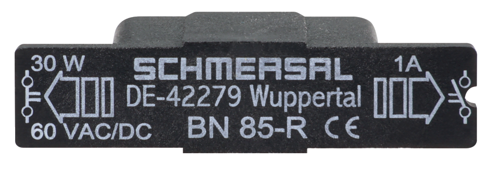
ID: kbn85f04
| 227,6 kB | .jpg | 352.778 x 130.528 mm - 1000 x 370 px - 72 dpi
| 28,7 kB | .png | 74.083 x 27.517 mm - 210 x 78 px - 72 dpi
| 198,5 kB | .jpg | 352.778 x 130.528 mm - 1000 x 370 px - 72 dpi
| 24,7 kB | .png | 74.083 x 27.517 mm - 210 x 78 px - 72 dpi
| 24,7 kB | .png | 74.083 x 27.517 mm - 210 x 78 px - 72 dpi
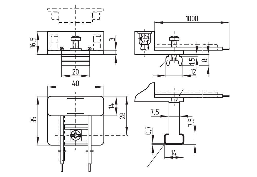
Dimensional drawing basic component
Diagram
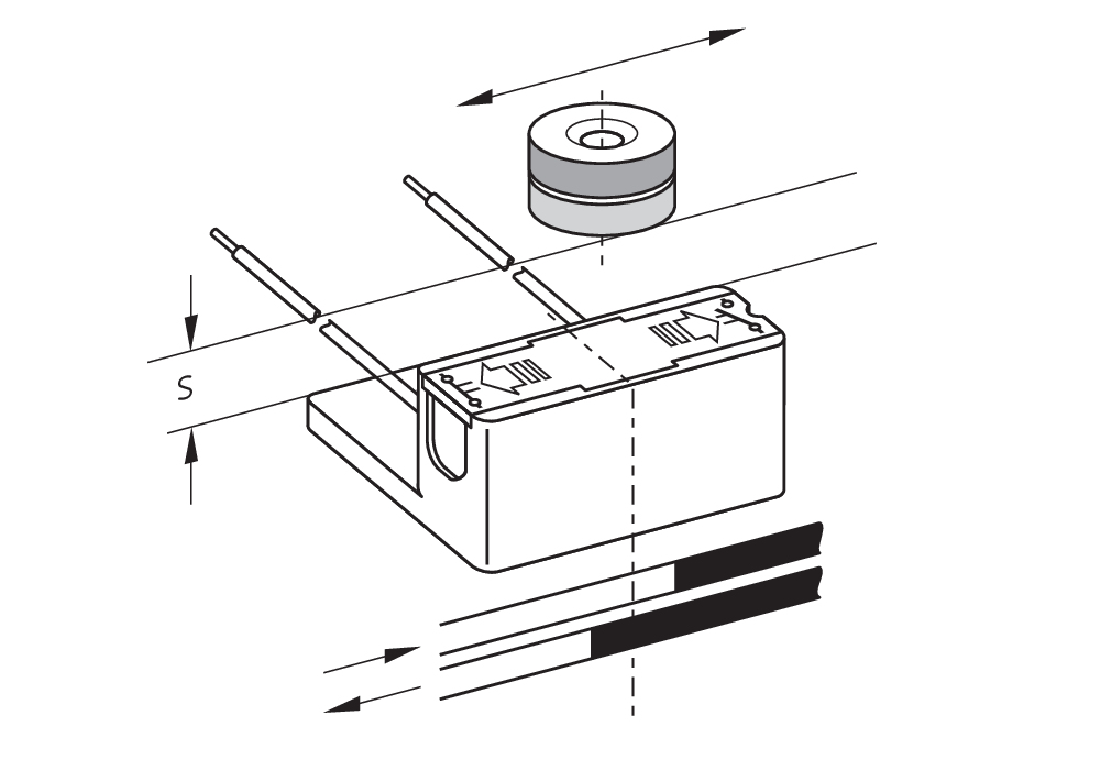
Characteristic curve

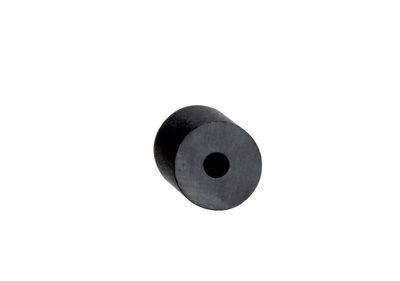
101054816 BP 8
- Unenclosed
- S-pole marked red
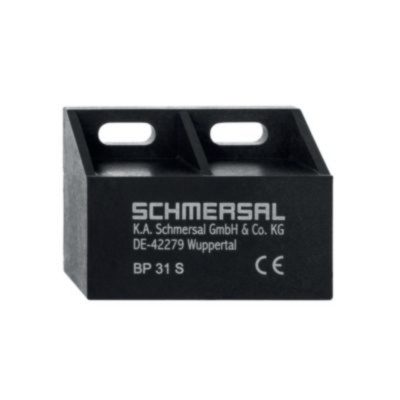
101057521 BP 31 S
- thermoplastic enclosure
- S-pole marked red
- Suitable for mounting on ferrous material with a distance of 20 mm
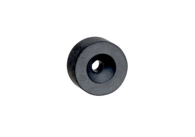
101057531 BP 10
- Unenclosed
- Colour coding of poles by lables
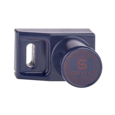
101057532 BP 12 S
- -metal housing
- S-pole marked red
- Suitable for mounting on ferrous material
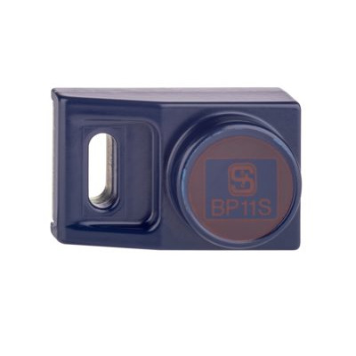
101057533 BP 11 S
- -metal housing
- S-pole marked red
- Suitable for mounting on ferrous material
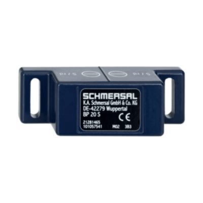
101057541 BP 20 S
- -metal housing
- S-pole marked red
- Suitable for mounting on ferrous material with a distance of 20 mm
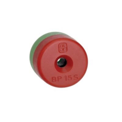
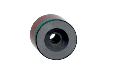
101060163 BP 15
- thermoplastic enclosure
- N-pole marked green
- S-pole marked red
- Suitable for mounting on ferrous material with a distance of 18 mm
101091837 BP 6
- Unenclosed
- S-pole marked red
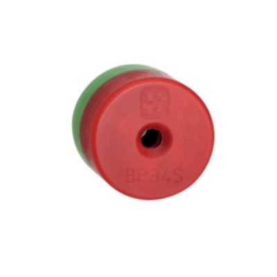
151057553 BP34
- thermoplastic enclosure
- S-pole marked red
- N-pole marked green
- Suitable for mounting on ferrous material with a distance of 25 mm
Schmersal India Pvt. Ltd., Plot No - G-7/1, Ranjangaon MIDC, Tal. - Shirur, Dist.- Pune 412 220
データと詳細は完全にチェックされました。画像は元の画像と異なる場合があります。技術的なデータはマニュアルで見られます。技術的に変更されたり、エラーの可能性があります。
Generated on 2025/08/25 11:00