MZM 100 ST2-1P2PWREM-A
| 製品タイプの説明: MZM 100 (1) (2)-(3)(4)(5)-A |
| (1) | |
| なし | ロック監視 > |
| B | アクチュエーター監視 |
| (2) | |
| ST | コネクターM12, 8芯 |
| (3) | |
| 1P2P | シリアル診断出力及び2 PNP安全出力 |
| (4) | |
| なし | ラッチなし (「電磁ロック付きインターロック監視」の時のみ) |
| R | 電気的ラッチ力、通常 30 N |
| (5) | |
| M | 永久磁石、通常 15 N |
- Guard locking monitored
- Connector M12, 8-pole
- Power to lock
- Automatic latching
- Solenoid interlocks with innovating and unique operating principle
- 40 mm x 179 mm x 40 mm
- Electronic contact-free, coded system
- Thermoplastic enclosure
- Max. length of the sensor chain 200 m
- 3 LEDs to show operating conditions
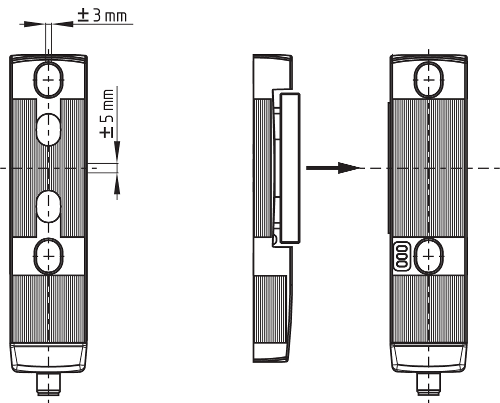
- Sensor technology permits an offset between actuator and interlock of ± 5 mm vertically and ± 3 mm horizontally
- Intelligent diagnosis
- Self-monitoring series-wiring
- Patented
Ordering data
| Product type description |
MZM 100 ST2-1P2PWREM-A |
| Article number (order number) |
101211067 |
| EAN (European Article Number) |
4030661389134 |
| eCl@ss number, version 12.0 |
27-27-26-03 |
| eCl@ss number, version 11.0 |
27-27-26-03 |
| eCl@ss number, version 9.0 |
27-27-26-03 |
| ETIM number, version 7.0 |
EC002593 |
| ETIM number, version 6.0 |
EC002593 |
Approvals - Standards
| Certificates |
TÜV cULus UKCA |
General data
| Standards |
EN ISO 13849-1 EN ISO 14119 EN IEC 60947-5-3 EN IEC 61508 |
| Coding |
ユニバーサルコード化 |
| Coding level according to EN ISO 14119 |
Low |
| Working principle |
誘導型 |
| Housing material |
樹脂、グラスファイバー強化熱可塑性樹脂、自己消火性 |
| Reaction time, maximum |
150 ms |
| Duration of risk, maximum |
150 ms |
| Gross weight |
698 g |
General data - Features
| Power to lock |
Yes |
| Solenoid interlock monitored |
Yes |
| Latching |
Yes |
| Short circuit detection |
Yes |
| Cross-circuit detection |
Yes |
| Series-wiring |
Yes |
| Safety functions |
Yes |
| Integral system diagnostics, status |
Yes |
| Number of safety contacts |
2 |
| Safety classification |
| Vorschriften |
EN ISO 13849-1 EN IEC 61508 |
Safety classification - Interlocking function
| Performance Level, up to |
e |
| Category |
4 |
| PFH value |
3.54 x 10⁻⁹ /h |
| Safety Integrity Level (SIL), suitable for applications in |
3 |
| Mission time |
20 Year(s) |
Mechanical data
| Mechanical life, minimum |
1,000,000 Operations |
| Note (Mechanical life) |
Actuating speed ≤ 0.5 m/s Operations for door weights ≤ 5 kg |
| Holding force, typically |
750 N |
| Holding force, guaranteed |
500 N |
| Latching force, minimum |
45 N |
| Latching force, maximum |
115 N |
| Type of the fixing screws |
2x M6 |
| Tightening torque of the fixing screws |
8 Nm |
Mechanical data - Switching distances
| Assured switching distance "ON" Sao |
0 mm |
| Assured switching distance "OFF" Sar |
1 mm |
| Note (switching distance) |
All switching distances in accordance EN IEC 60947-5-3 |
Mechanical data - Connection technique
| Length of sensor chain, maximum |
200 m |
| Note (length of the sensor chain) |
ケーブル長とケーブル径により、出力電流による電圧降下が変化します。 |
| Note (series-wiring) |
無制限のデバイス数,外部ラインヒューズオーバーサーブ、シリアル診断SDの場合、最大31デバイス。 |
| Termination |
M12コネクター, 8芯 |
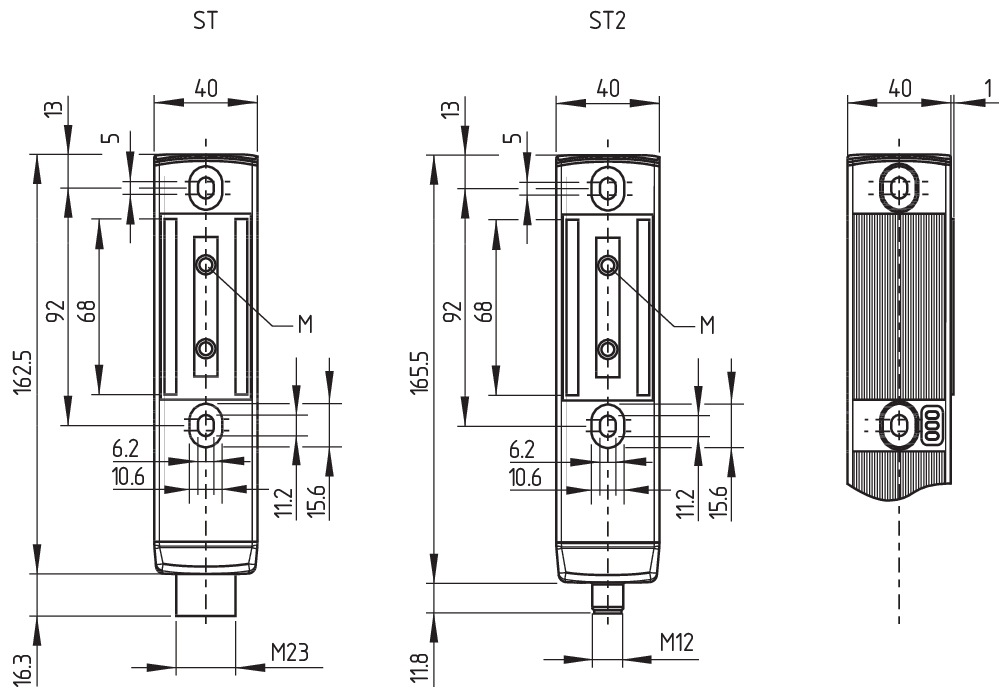
Mechanical data - Dimensions
| Length of sensor |
40 mm |
| Width of sensor |
40 mm |
| Height of sensor |
177.5 mm |
Ambient conditions
| Degree of protection |
IP65 IP67 |
| Ambient temperature |
-25 ... +55 °C |
| Storage and transport temperature |
-25 ... +70 °C |
| Relative humidity, minimum |
30 % |
| Relative humidity, maximum |
95 % |
| Note (Relative humidity) |
non-condensing non-icing |
| Resistance to vibrations |
10 ~ 150 Hz, 振幅 0.35 mm / 5 g |
| Restistance to shock |
30 g / 11 ms |
| Protection class |
III |
| Permissible installation altitude above sea level, maximum |
2,000 m |
Ambient conditions - Insulation values
| Rated insulation voltage Ui |
32 VDC |
| Rated impulse withstand voltage Uimp |
0.8 kV |
| Overvoltage category |
III |
| Degree of pollution |
3 |
Electrical data
| Operating voltage |
24 VDC -15 % / +10 % (PELV電源により安定化) |
| No-load supply current I0, typical |
100 mA |
| Current consumption with magnet ON, average |
350 mA |
| Current consumption with magnet ON, peak |
550 mA / 10 ms |
| Rated operating voltage |
24 VDC |
| Operating current |
1,100 mA |
| Required rated short-circuit current |
100 A |
| External wire and device fuse rating |
2 A gG |
| Time to readiness, maximum |
4,000 ms |
| Switching frequency, maximum |
1 Hz |
Electrical data - Magnet control
| Designation, Magnet control |
IN |
| Switching thresholds |
-3 V … 5 V (Low) 15 V … 30 V (High) |
| Current consumption at 24 V |
10 mA |
| Magnet switch-on time |
100 % |
| Test pulse duration, maximum |
5 ms |
| Test pulse interval, minimum |
40 ms |
| Classification ZVEI CB24I, Sink |
C0 |
| Classification ZVEI CB24I, Source |
C1 C2 C3 |
Electrical data - Safety digital inputs
| Designation, Safety inputs |
X1 and X2 |
| Switching thresholds |
−3 V … 5 V (Low) 15 V … 30 V (High) |
| Current consumption at 24 V |
5 mA |
| Test pulse duration, maximum |
1 ms |
| Test pulse interval, minimum |
100 ms |
| Classification ZVEI CB24I, Sink |
C1 |
| Classification ZVEI CB24I, Source |
C1 C2 C3 |
Electrical data - Safety digital outputs
| Designation, Safety outputs |
Y1 and Y2 |
| Rated operating current (safety outputs) |
250 mA |
| Design of control elements |
short-circuit proof, p-type |
| Voltage drop Ud, maximum |
1 V |
| Leakage current Ir, maximum |
0.5 mA |
| Voltage, Utilisation category DC-13 |
24 VDC |
| Current, Utilisation category DC-13 |
0.25 A |
| Test pulse interval, typical |
1000 ms |
| Test pulse duration, maximum |
1 ms |
| Classification ZVEI CB24I, Source |
C1 |
| Classification ZVEI CB24I, Sink |
C1 |
Electrical data - Diagnostic outputs
| Designation, Diagnostic outputs |
OUT |
| Design of control elements |
short-circuit proof, p-type |
| Voltage drop Ud, maximum |
2 V |
| Voltage, Utilisation category DC-13 |
24 VDC |
| Current, Utilisation category DC-13 |
0.05 A |
Status indication
| Note (LED switching conditions display) |
Operating condition: LED green Error / functional defect: LED red Supply voltage UB: LED green |
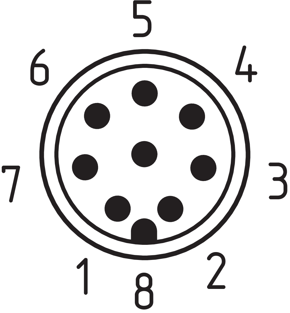
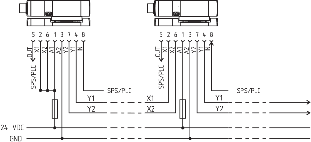
Pin assignment
| PIN 1 |
A1 Supply voltage UB |
| PIN 2 |
X1 Safety input 1 |
| PIN 3 |
A2 GND |
| PIN 4 |
Y1 Safety output 1 |
| PIN 5 |
OUT Diagnostic output |
| PIN 6 |
X2 Safety input 2 |
| PIN 7 |
Y2 Safety output 2 |
| PIN 8 |
IN Solenoid control |
Scope of delivery
| Scope of delivery |
Actuator must be ordered separately. |
Accessory
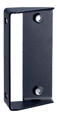
| Recommendation (actuator) |
MZM 100-B1.1 |
Note
| Note (General) |
As long as the actuating unit is applied to the solenoid interlock, the unlocked safety guard can be relocked. In this case, the safety outputs are re-enabled, so that the safety guard must not be opened. |
言語フィルター
データシート
Operating instructions and Declaration of conformity
TÜV certification
UL Certificate
UKCA certificate
SISTEMA-VDMA library
Adobe Readerの最新版をダウンロードしてください
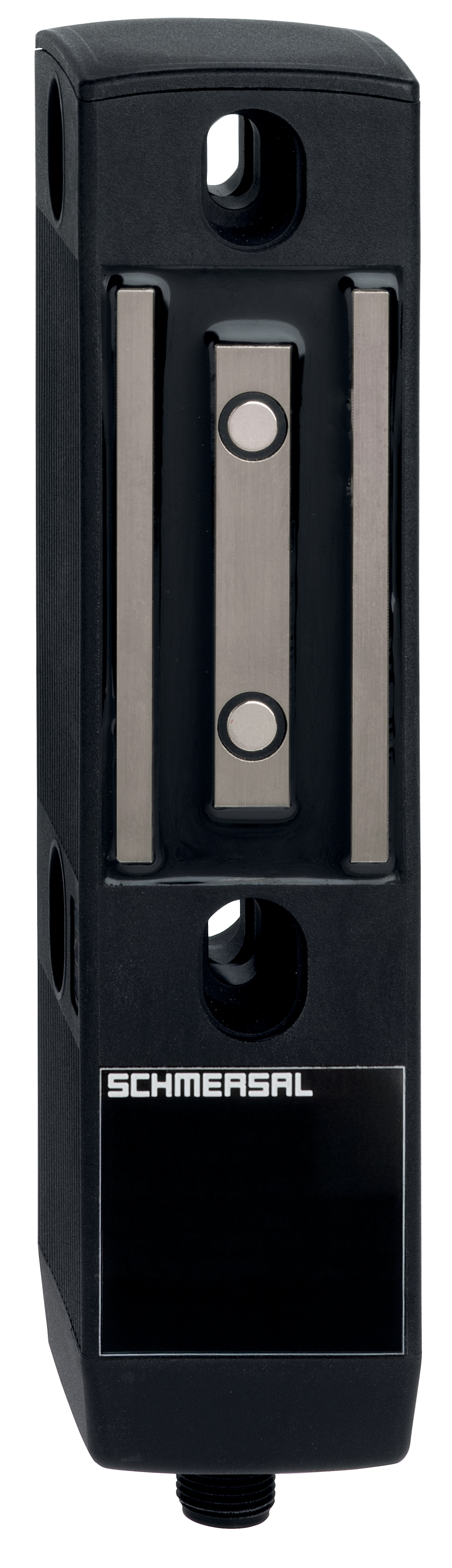
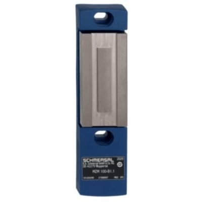
Product picture (catalogue individual photo)
Dimensional drawing basic component
Dimensional drawing miscellaneous
Contact arrangement
Wiring example

103009970 SRB-E-201LC
- Plug-in screw terminals with coding
- STOP 0 Function
- 1 oder 2-channel control
- Start button / Auto-start
- 2 Safety outputs 2 A
- 1 Signalling output

103007672 SRB-E-301ST
- Plug-in screw terminals with coding
- STOP 0 Function
- 1 oder 2-channel control
- Start button / Auto-start
- 1 Auxiliary contact
- 3 safety contacts

103009973 SRB-E-204ST
- Plug-in screw terminals with coding
- STOP 0 Function
- Monitoring of 4 sensors
- Start button / Auto-start
- 2 Safety outputs
- 4 Signalling outputs
101204290 MZM 100-B1.1
- actuator free from play
- neutralisation of undesired noises
101210642 MZM 100 TARGET
- for the variable setting of the latching force
- gradually adjustable by steps of approx. 10 N within a range from approx. 30 N to 100 N
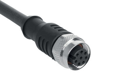
103007358 A-K8P-M12-S-G-5M-BK-2-X-A-4-69
- 5 m
- Pre-wired cable
- 8-pole
103007359 A-K8P-M12-S-G-10M-BK-2-X-A-4-69
- 10 m
- Pre-wired cable
- 8-pole
103011415 A-K8P-M12-S-G-2.5M-BK-2-X-A-4-69
- 2.5 m
- Pre-wired cable
- 8-pole
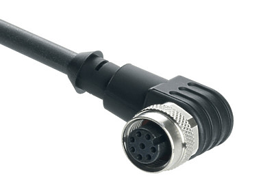
103043110 A-K8P-M12-S-W-2,5M-BK-2-X-A-4
- angled
- 2.5 m
- Pre-wired cable
- 8-pole
103043119 A-K8P-M12-S-W-5M-BK-2-X-A-4
- angled
- 5 m
- Pre-wired cable
- 8-pole
103043120 A-K8P-M12-S-W-10M-BK-2-X-A-4
- angled
- 10 m
- Pre-wired cable
- 8-pole
103043121 A-K8P-M12-S-W-15M-BK-2-X-A-4
- angled
- 15
- Pre-wired cable
- 8-pole
| UK Declaration of Conformity |  |
| Company: | K.A. Schmersal GmbH & Co. KG Möddinghofe 30 42279 Wuppertal Germany Internet: www.schmersal.com |
| Declaration: | We hereby, under sole responsibility, certify that the hereafter described components both in their basic design and construction conform to the relevant statutory requirements, regulations and designated standards of the United Kingdom. |
| Name of the component: | MZM 100 MZM 100 B |
| Type: | See ordering code |
| Description of the component: | Interlocking device with electromagnetic interlock for safety functions (MZM 100) and safety switch with interlocking functions (MZM 100 B) |
| Relevant legislation: | Supply of Machinery (Safety) Regulations | 2008 |
| Electromagnetic Compatibility Regulations | 2016 | |
| The Restriction of the Use of Certain Hazardous Substances in Electrical and Electronic Equipment Regulations | 2012 |
| Designated standards: | EN 60947-5-3:2013 EN ISO 14119:2013 EN ISO 13849-1:2015 IEC 61508 parts 1-7:2010 |
| Approved body for Type Examination: | TÜV Rheinland UK Ltd. 1011 Stratford Road Solihull, B90 4BN ID: 2571 |
| Type examination certificate: | 01/205U/5778.00/23 |
| UK-Importer / Person authorised for the compilation of the technical documentation: | Schmersal UK Ltd. Paul Kenney Unit 1, Sparrowhawk Close Enigma Business Park Malvern, Worcestershire, WR14 1GL |
| Place and date of issue: | Wuppertal, April 18, 2023 |
 |
| Authorised signature Philip Schmersal Managing Director |
| EU Declaration of Conformity | |
| Original | K.A. Schmersal GmbH & Co. KG Möddinghofe 30 42279 Wuppertal Germany Internet: www.schmersal.com |
| Declaration: | We hereby certify that the hereafter described components both in their basic design and construction conform to the applicable European Directives. |
| Name of the component: | MZM 100 MZM 100 B |
| Type: | See ordering code |
| Description of the component: | Interlocking device with electromagnetic interlock for safety functions (MZM 100) and safety switch with interlocking functions (MZM 100 B) |
| Relevant Directives: | Machinery Directive | 2006/42/EC |
| EMC-Directive | 2014/30/EU | |
| RoHS-Directive | 2011/65/EU |
| Applied standards: | EN 60947-5-3:2013 EN ISO 14119:2013 EN ISO 13849-1:2015 IEC 61508 parts 1-7:2010 |
| Notified body for Type Examination: | TÜV Rheinland Industrie Service GmbH Am Grauen Stein, 51105 Köln ID n°: 0035 |
| EC-Type Examination Certificate: | 01/205/5778.00/20 |
| Person authorised for the compilation of the technical documentation: | Oliver Wacker Möddinghofe 30 42279 Wuppertal |
| Place and date of issue: | Wuppertal, November 18, 2020 |
|
| Authorised signature Philip Schmersal Managing Director |
Schmersal India Pvt. Ltd., Plot No - G-7/1, Ranjangaon MIDC, Tal. - Shirur, Dist.- Pune 412 220
データと詳細は完全にチェックされました。画像は元の画像と異なる場合があります。技術的なデータはマニュアルで見られます。技術的に変更されたり、エラーの可能性があります。
Generated on 2025/06/22 13:30