AES 2335 UE: 24...230V AC/DC

AES 2335 UE: 24...230V AC/DC
- BNSシリーズのセーフティ磁気センサの監視
- 3 安全出力, STOP 0
- 2 補助出力
注文データ
| Note (Delivery capacity) |
Phased-out product |
| Product type description |
AES 2335 UE: 24...230V AC/DC |
| 部品番号(注文番号) |
101180843 |
| EAN(欧州部品番号) |
4030661338507 |
| eCl@ss number, version 12.0 |
27-37-18-19 |
| eCl@ss number, version 11.0 |
27-37-18-19 |
| eCl@ss番号、バージョン9.0 |
27-37-18-19 |
| ETIM number, version 7.0 |
EC001449 |
| ETIM number, version 6.0 |
EC001449 |
| Available until |
31.12.2024 |
認証
| 証明書 |
BG cULus |
一般データ
| 規格 |
BG-GS-ET-14 BG-GS-ET-20 EN IEC 62061 EN IEC 60947-5-1 EN IEC 60947-5-3 EN IEC 60947-5-5 EN IEC 61508 EN IEC 60204-1 EN IEC 60947-1 |
| 環境ストレス |
EN 60068-2-3 BG-GS-ET-14 |
| ハウジング 材質 |
グラスファイバー強化熱可塑性樹脂 |
| 総重量 |
350 g |
一般データ - 仕様
| 断線検出 |
Yes |
| 短絡監視 |
Yes |
| バックチェック回路 |
Yes |
| 自動リセット機能 |
Yes |
| 供給電圧切断後のリセット |
Yes |
| 一体型システム診断、状態 |
Yes |
| LEDの数 |
1 |
| NC接点の数 |
2 |
| NO接点の数 |
1 |
| 数、信号機能付き遅延のない半導体出力の数 |
2 |
| 安全接点数 |
3 |
| 信号出力数 |
2 |
安全性評価
| 規格 |
EN ISO 13849-1 EN IEC 61508 |
| 停止カテゴリー |
0 |
安全性評価 - リレー出力
| Performance Level, up to |
d |
| Category |
3 |
| PFH value |
1.00 x 10⁻⁷ /h |
| Notice |
for max. 50,000 switching cycles/year and max. 80% contact load |
| Safety Integrity Level (SIL), suitable for applications in |
2 |
| Mission time |
20 年 |
機械的データ
| 機械的寿命、最小 |
20,000,000 操作 |
| 取り付け |
EN 60715に基づくDINレールにワンタッチ取り付け |
機械的データ - 電気機械式
| 配線表示 |
IEC/EN 60947-1 |
| 端子 コネクター |
単線 / 撚線 ネジ端子 M20 x 1.5 |
| ケーブル断面積、最小 |
0.25 mm² |
| ケーブル断面積, 最大 |
2.5 mm² |
| クリップの締付トルク |
0.6 Nm |
機械的データ - 寸法
| 幅 |
45 mm |
| 高さ |
100 mm |
| 深さ |
121 mm |
環境条件
| ハウジングの保護等級 |
IP40 |
| 取付領域の保護等級 |
IP54 |
| クリップまたは端子の保護等級 |
IP20 |
| Ambient temperature |
+0 ... +55 °C |
| Storage and transport temperature |
-25 ... +70 °C |
| EN 60068-2-6に基づく耐振動 |
10 ~ 55 Hz、振幅 0.35 mm、± 15 % |
| 耐衝撃 |
30 g / 11 ms |
環境条件 - 絶縁値
| 定格インパルス耐電圧 |
4 kV |
| Overvoltage category |
III |
| IEC/EN 60664-1に準拠した汚染度 |
2 |
電気的データ
| 周波数範囲 |
50 Hz 60 Hz |
| Type of voltage range |
AC DC |
| 熱試験電流 |
6 A |
| Rated operating voltage |
24 ... 230 VAC |
| 制御用定格AC電圧、50 Hz、最小 |
20.4 VAC |
| 定格制御電圧 AC 50 Hzにて、最大 |
253 VAC |
| 制御用定格AC電圧、60 Hz、最小 |
20.4 VAC |
| 定格制御電圧 AC 60 Hzにて、最大 |
253 VAC |
| DC最小で制御するための定格AC電圧 |
20.4 VDC |
| 定格制御電圧 DCにて、最大 |
253 VDC |
| 消費電力 |
5 W |
| 接点抵抗, 最大 |
0.1 Ω |
| 注意(接点抵抗) |
新しい状態で |
| 停電時の遮断遅延、通常 |
80 ms |
| 「非常停止」時の遮断遅延、通常 |
20 ms |
| 自動リセット時の立ち上がり遅延、通常 |
100 ms |
| リセット時の立ち上がり遅延、通常 |
20 ms |
| 接点材質、電気的 |
Ag-Ni 10および0.2 µm 金メッキ |
電気的データ - 安全リレー出力
| Voltage, Utilisation category AC-15 |
230 VAC |
| Current, Utilisation category AC-15 |
3 A |
| Voltage, Utilisation category DC-13 |
24 VDC |
| Current, Utilisation category DC-13 |
2 A |
| Switching capacity, minimum |
10 VDC |
| Switching capacity, minimum |
10 mA |
| Switching capacity, maximum |
250 VAC |
| Switching capacity, maximum |
8 A |
電気的データ - デジタル入力
| 入力信号, HIGH信号 "1" |
10 … 30 VDC |
| 入力信号、LOW信号 "0" |
0 … 2 VDC |
| 配線抵抗, 最大 |
40 Ω |
電気的データ - デジタル出力
| Voltage, Utilisation category DC-12 |
24 VDC |
| Current, Utilisation category DC-12 |
0.1 A |
電気的データ - リレー出力 (補助接点)
| Switching capacity, maximum |
24 VDC |
| Switching capacity, maximum |
2 A |
電気的データ - 電磁両立性 (EMC)
| EMC rating |
EMC-Directive |
Integral system diagnosis (ISD)
| Note (ISD -Faults) |
The following faults are registered by the safety monitoring modules and indicated by ISD. |
| Faults |
Failure of the safety relay to pull-in or drop-out Failure of door contacts to open or close Cross-wire or short-circuit monitoring of the switch connections Interruption of the switch connections Fault on the input circuits or the relay control circuits of the safety monitoring module Failure of or functional fault on the safety relay |
その他のデータ
| 注意 (アプリケーション) |
セーフティセンサー ガードシステム |
Note
| Note (General) |
Inductive loads (e.g. contactors, relays, etc.) are to be suppressed by means of a suitable circuit. |
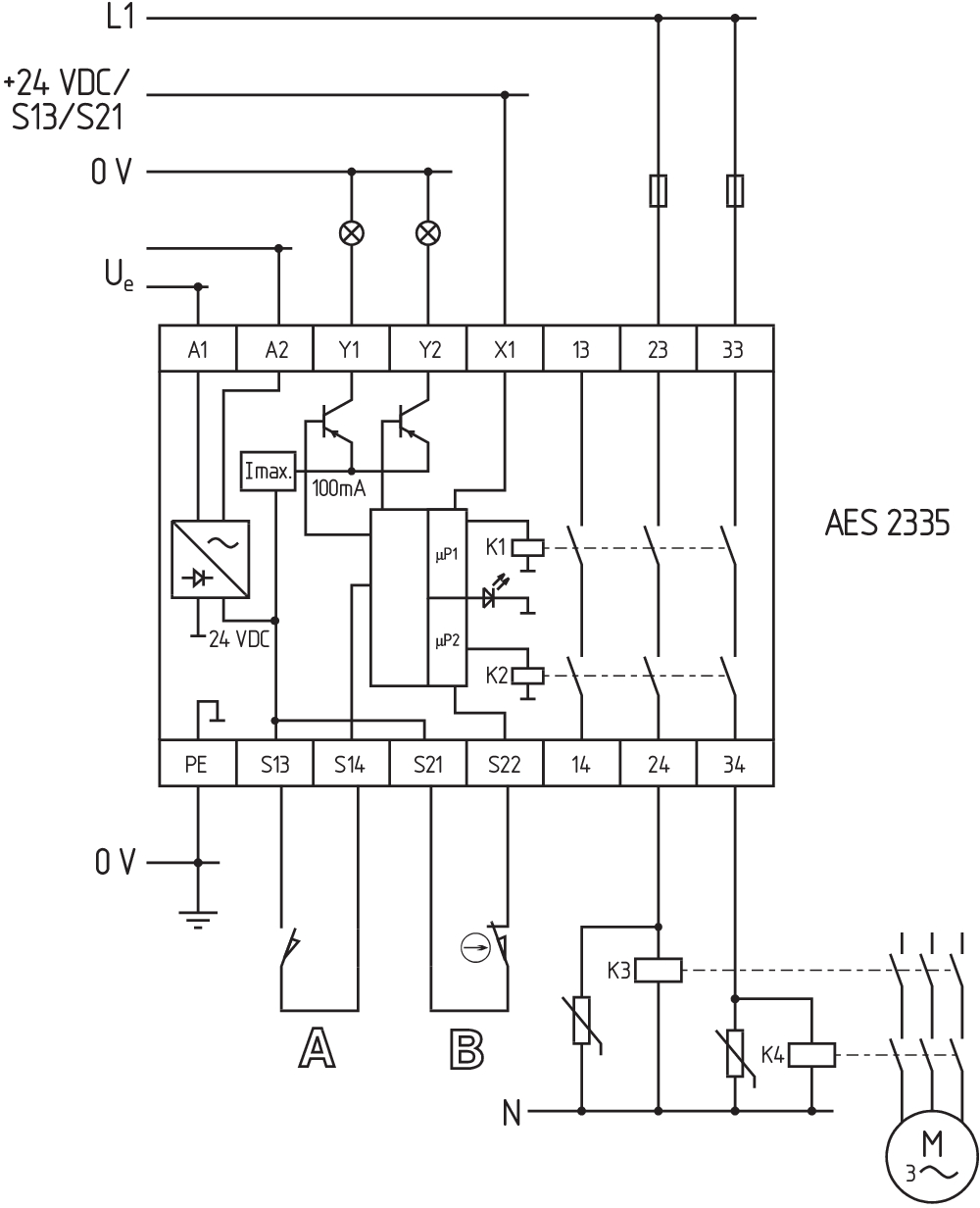
回路例
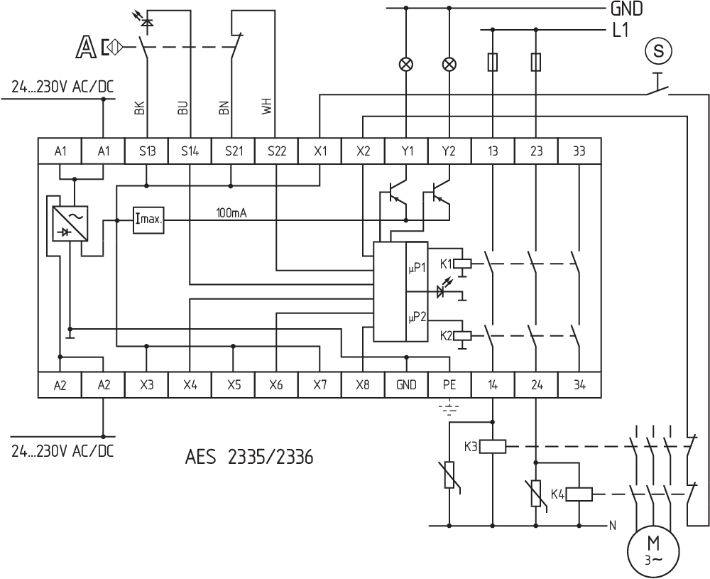
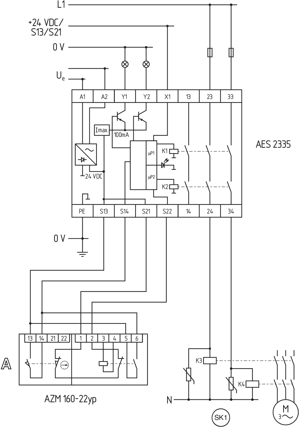
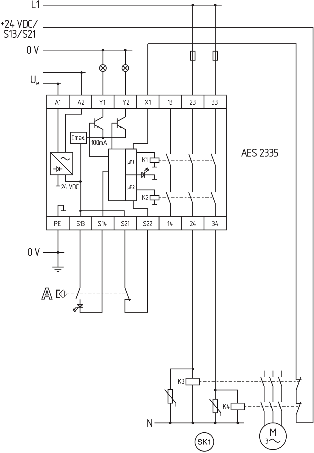
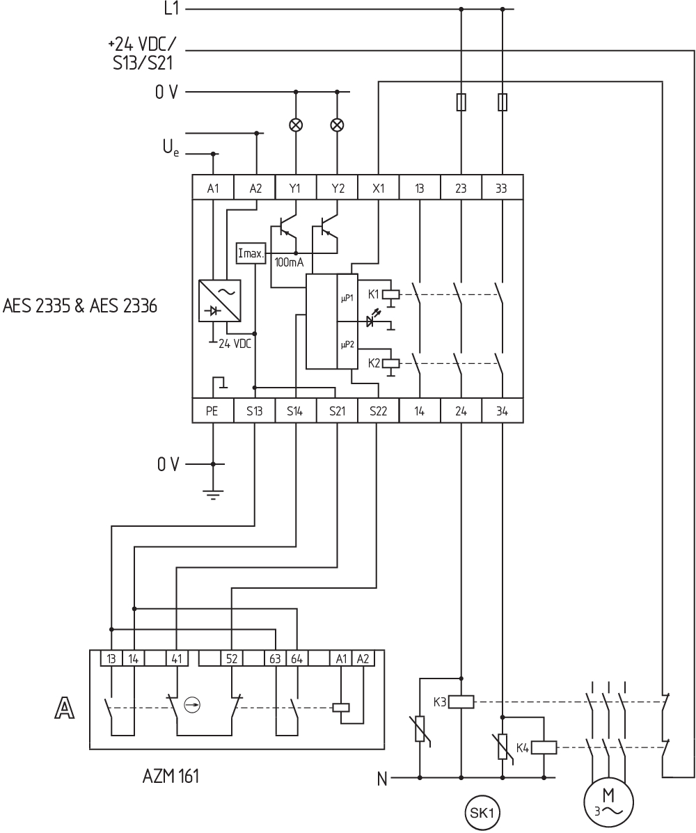
| Note (Wiring diagram) |
The wiring diagram is shown with guard doors closed and in de-energised condition. To secure a guard door up to PL d and Category 3 The ISD tables (Intergral System Diagnostics) for analysis of the fault indications and their causes are shown in the appendix. Start push button: A start push button (NO) can optionally be connected into the feedback circuit. With the guard door closed, the enabling paths are then not closed until the start push button has been operated. Modification for 2 NC contacts: The safety monitoring module can be modified to monitor two NC contacts by bridging the terminals X3 and X4. In this configuration, the short-circuit detection becomes inoperative. Inversion of the output function: By establishing a bridge between X5 and X6, the output function of the additional outputs can be altered. This control can also be realised when e.g. a PLC is running (24 VDC at terminal X6). Expansion of the enable delay time. The enable delay time can be increased from X7 s to X8 s by mounting a jumper connection between the terminals 0,1 and 1. Monitoring a guard door using 2 position switches with safety function. The NC contact A must have positive break when the guard door is opened. Category 3 to ISO 13849-1 can also be achieved using only one safety switch with one NO and one NC contact. Exclusion of faults due to breakage or loosening of the actuating element or the actuating head as well as releasing, dismantling. The feedback circuit monitors the position of the positive-guided NC contacts of the contactors K3 and K4. If neither start button nor feedback circuit are connected, a jumper connection must be mounted between X1 and X2. |
言語フィルター
データシート
Operating instructions and Declaration of conformity
UL Certificate
Wiring example (electr. wiring)
Force-travel diagram
SISTEMA-VDMA library
Adobe Readerの最新版をダウンロードしてください
Product picture (catalogue individual photo)
Wiring example
Wiring example
Wiring example
Wiring example
Wiring example

103009970 SRB-E-201LC
- STOP 0 機能
- 1 oder 2チャンネルコントロール
- リセットボタン / 自動リセット
- 2 安全出力 2 A
- 1 補助出力

103007672 SRB-E-301ST
- STOP 0 機能
- 1 oder 2チャンネルコントロール
- リセットボタン / 自動リセット
- 1 補助接点
- 3 安全出力
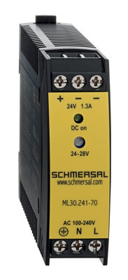
103015923 ML30.241-70
- 1-phase DIN rail power supplies
- AC 100-240V Wide-range input
- DC Output 24-28VDC / 1,3-1,1A / 30W
- Efficiency up to 89,4%
- Width only 22,5mm
| EU-Konformitätserklärung |  |
| Original | K.A. Schmersal GmbH & Co. KG Möddinghofe 30 42279 Wuppertal Germany Internet: www.schmersal.com |
| Erklärung: | Hiermit erklären wir, dass die nachfolgend aufgeführten Bauteile aufgrund der Konzipierung und Bauart den Anforderungen der unten angeführten Europäischen Richtlinien entsprechen. |
| Bezeichnung des Bauteils: | AES 1135/1136 AES 1165/1165-2250 AES 1235/1236 AES 1265/1265-2250 AES 2135 AES 2335/2365 AES 2535 |
| Typ: | siehe Typenschlüssel |
| Beschreibung des Bauteils: | Sicherheitsauswertung |
| Einschlägige Richtlinien: | Maschinenrichtlinie | 2006/42/EG |
| EMV-Richtlinie | 2014/30/EU | |
| RoHS-Richtlinie | 2011/65/EU |
| Angewandte Normen: | DIN EN 60947-5-1:2018 DIN EN ISO 13849-1:2016 DIN EN ISO 13849-2:2013 |
| Benannte Stelle für die Zertifizierung des QS-Systems nach Anhang X, 2006/42/EG: | TÜV Rheinland Industrie Service GmbH Am Grauen Stein, 51105 Köln Kenn-Nr.: 0035 |
| Bevollmächtigter für die Zusammenstellung der technischen Unterlagen: | Oliver Wacker Möddinghofe 30 42279 Wuppertal |
| Ort und Datum der Ausstellung: | Wuppertal, 31. Januar 2024 |
 |
| Rechtsverbindliche Unterschrift Philip Schmersal Geschäftsführer |
シュメアザー株式会社, 〒222-0033 横浜市港北区新横浜3-9-5, 新横浜第3東昇ビル
データと詳細は完全にチェックされました。画像は元の画像と異なる場合があります。技術的なデータはマニュアルで見られます。技術的に変更されたり、エラーの可能性があります。
Generated on 2024/04/19 21:27