AZM 161SK-12/12RKED/TU -110/230

AZM 161SK-12/12RKED/TU -110/230
- 広い配線用スペース
- マニュアル・リリース, カバー側 と 緊急脱出, 背面
- ケーブル引込口 4 M 16 x 1.5
- 熱可塑性樹脂性ケース
- 二重絶縁
- 空閉じ防止機能
- 130 mm x 90 mm x 30 mm
- 6 接点
- 長寿命
注文データ
| Note (Delivery capacity) |
Not available! |
| Product type description |
AZM 161SK-12/12RKED/TU -110/230 |
| 部品番号(注文番号) |
101187914 |
| EAN(欧州部品番号) |
4030661357300 |
| eCl@ss number, version 12.0 |
27-27-26-03 |
| eCl@ss number, version 11.0 |
27-27-26-03 |
| eCl@ss番号、バージョン9.0 |
27-27-26-03 |
| ETIM number, version 7.0 |
EC002593 |
| ETIM number, version 6.0 |
EC002593 |
認証
| 証明書 |
cULus CCC |
一般データ
| 規格 |
EN ISO 13849-1 EN ISO 14119 EN IEC 60947-5-1 |
| Coding level according to EN ISO 14119 |
Low |
| アクティブ原理 |
電気機械式 |
| ハウジング 材質 |
樹脂、グラスファイバー強化熱可塑性樹脂、自己消火性 |
| 総重量 |
495 g |
一般データ - 仕様
| スプリングロック |
Yes |
| 緊急脱出 |
Yes |
| 手動解除 |
Yes |
| 動作方向の数 |
3 |
| 補助接点数 |
2 |
| 安全接点数 |
4 |
安全性評価
| 規格 |
EN ISO 13849-1 |
| Performance Level, up to |
c |
| EN ISO 13849に準拠したカテゴリー |
1 |
| B10D Normally-closed contact (NC) |
2,000,000 操作 |
| Note |
Electrical life on request. |
| B10D Normally-open contact (NO) |
1,000,000 操作 |
| Note |
at 10% Ie and ohmic load |
| Mission time |
20 年 |
安全性評価 - 障害の除外
| Please note: |
Can be used when fault exclusion for dangerous damage to the 1-channel mechanism is permissible and sufficient protection against manipulation is guaranteed. |
| Performance Level, up to |
d |
| Category |
3 |
| Note |
for 2-channel use and with suitable logic unit. |
| Mission time |
20 年 |
安全性評価 - ガードロック
| Performance Level, up to |
e |
| Note (Performance Level) |
Information for the safety classification of the guard locking function is documented in the "Operating instructions" or in the "Operation and mounting" instructions. |
機械的データ
| 機械的寿命、最小 |
1,000,000 操作 |
| 動作方向のアクチュエータの遊び |
5.5 mm |
| EN ISO 14119 に準拠したクロック時引抜強度 |
2,000 N |
| ロック時引抜強度, 最大 |
2,600 N |
| ラッチ力 |
30 N |
| 強制開離距離 |
10 mm |
| Positive break force per NC contact, minimum |
10 N |
| 強制開離力、最小 |
20 N |
| 作動速度, 最大 |
2 m/s |
| 取り付け |
ネジ |
| Type of the fixing screws |
3x M5 |
| Type of the screw head |
Flat head screw |
機械的データ - 電気機械式
| ケーブル引込口 |
4 x M16 x 1,5 |
| ケーブル断面積、最小 |
0.25 mm² |
| ケーブル断面積, 最大 |
1.5 mm² |
| Note |
All indications including the conductor ferrules. |
| Allowed type of cable |
solid single-wire solid multi-wire flexible |
機械的データ - 寸法
| センサー長 |
30 mm |
| センサーの幅 |
130 mm |
| センサーの高さ |
90 mm |
環境条件
| 保護等級 |
IP67 |
| Ambient temperature |
-30 ... +60 °C |
| Storage and transport temperature |
-30 ... +85 °C |
| Note (Relative humidity) |
non-condensing non-icing |
| Protection class |
II |
| Permissible installation altitude above sea level, maximum |
2,000 m |
環境条件 - 絶縁値
| 定格絶縁電圧 |
250 VAC |
| 定格インパルス耐電圧 |
4 kV |
電気的データ
| 熱試験電流 |
6 A |
| 定格制御電圧 |
110 VAC 230 VAC |
| EN 60947-5-1 に基づく要求定格短絡電流 |
1,000 A |
| 消費電力、最大 |
10 W |
| スイッチ素子 |
NO 接点、NC 接点 |
| スイッチ原理 |
スローアクション |
| 開閉頻度 |
1,000 /h |
| 接点材質、電気的 |
銀 |
電気的データ - ソレノイド制御
| Magnet switch-on time |
100 % |
| Test pulse duration, maximum |
5 ms |
| Test pulse interval, minimum |
50 ms |
Electrical data - Safety contacts
| Voltage, Utilisation category AC-15 |
230 VAC |
| Current, Utilisation category AC-15 |
4 A |
| Voltage, Utilisation category DC-13 |
24 VDC |
| Current, Utilisation category DC-13 |
2.5 A |
Electrical data - Auxiliary contacts
| Voltage, Utilisation category AC-15 |
230 VAC |
| Current, Utilisation category AC-15 |
4 A |
| Voltage, Utilisation category DC-13 |
24 VDC |
| Current, Utilisation category DC-13 |
2.5 A |
その他のデータ
| 注意 (アプリケーション) |
スライド式ガード 取り外し可能なガード ヒンジ式ガード |
納入品目
| 納入時同梱 |
Actuator must be ordered separately. |
Note
| Note (Emergency exit) |
The emergency exit is used where an intervention in an already locked hazardous area is required Emergency exit by pressing the red push button Resetting by pulling on the latched button Top-side (ordering suffix -TD) or rear-side (ordering suffix -TU) mounting possible |
| Note (Manual release) |
For maintenance, installation, etc. For manual release using M5 triangular key, available as accessory Top-side (ordering suffix -ED) or rear-side (ordering suffix -EU) mounting possible |
| Note (Emergency exit, Manual release) |
A combination of manual release and emergency exit in different mounting directions in only possible for the following variants: -ED/-TU and -TD/-EU |
言語フィルター
データシート
Operating instructions and Declaration of conformity
Operating Instructions and Declaration of Conformity (Short)
CCC certification
UL Certificate
DGUV-Certificate
SISTEMA-VDMA library
Adobe Readerの最新版をダウンロードしてください
Product picture (catalogue individual photo)
Dimensional drawing basic component
Dimensional drawing miscellaneous
Dimensional drawing miscellaneous
Switch travel diagram
101175171 AZM 161-STS30-01
- ラッチングハンドル
- 全てのガードに適用可能
- 110℃まで取り付け可
101175178 AZM 161-STS30-02
- ラッチングハンドル
- 全てのガードに適用可能
- 110℃まで取り付け可
101175481 AZM 161-STS30-03
- ラッチングハンドル
- 全てのガードに適用可能
- 110℃まで取り付け可
101175486 AZM 161-STS30-04
- ラッチングハンドル
- 全てのガードに適用可能
- 110℃まで取り付け可
101175490 AZM 161-STS30-05
- ラッチングハンドル
- 全てのガードに適用可能
- 110℃まで取り付け可
101175491 AZM 161-STS30-06
- ラッチングハンドル
- 全てのガードに適用可能
- 110℃まで取り付け可
101173764 AZM 161-STS30-07
- ラッチングハンドル
- 全てのガードに適用可能
- 110℃まで取り付け可
101173763 AZM 161-STS30-08
- ラッチングハンドル
- 全てのガードに適用可能
- 110℃まで取り付け可
101145117 ACTUATOR AZM 161-B1
- ストレート型アクチュエータ
- スライド式扉に最適

101144416 ACTUATOR AZM 161-B1E
- ストレート型アクチュエータ
- スライド式扉に最適

101171859 ACTUATOR AZM 161-B1ES
- ストレート型アクチュエータ
- スライド式扉に最適

101175431 ACTUATOR AZM 161-B1F
- ストレート型アクチュエータ
- スライド式扉に最適

101171125 BETAETIGER AZM 161-B1S
- ストレート型アクチュエータ
- スライド式扉に最適

101170375 BETAETIGER AZM 161-B6S
- 作動半径が非常に小さい場合
101144420 ACTUATOR AZM 161-B6
- 可動式アクチュエータ
- ヒンジ式ガードに最適

101173089 AZM 161-B1-2053 NACHRUESTSATZ
- ストレート型アクチュエータ
- スライド式扉に最適

101164100 AZM 161-B1-1747 NACHRUESTSATZ
- スライド式扉に最適

101178199 AZM 161-B1-2024
- スライド式扉に最適

101176642 AZM 161-B1-2177 NACHRUESTSATZ
- スライド式扉に最適

101174113 AZM 161-B6-2177 MIT ZENTRIERHILFE
- 作動半径が非常に小さい場合
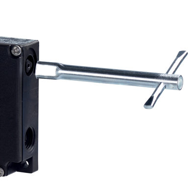
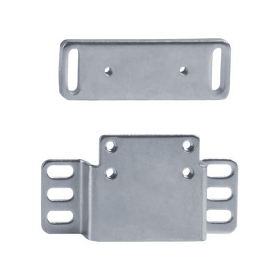
Table of Contents
- 1 About this document
- 1.1 Function
- 1.2 Target group of the operating instructions: authorised qualified personnel
- 1.3 Explanation of the symbols used
- 1.4 Appropriate use
- 1.5 General safety instructions
- 2 Product description
- 2.1 Ordering code
- 2.2 Special versions
- 2.3 Purpose
- 2.4 Warning about misuse
- 2.5 Exclusion of liability
- 2.6 Technical Data
- 3 Mounting
- 3.1 General mounting instructions
- 3.2 Dimensions
- 3.3 Manual release
- 3.4 Emergency release (ordering suffix -N)
- 3.5 Emergency Exit
- 4 Electrical connection
- 4.1 General information for electrical connection
- 4.2 Contact Options
- 5 Set-up and maintenance
- 6 Disassembly and disposal
- 6.1 Disassembly
- 6.2 Disposal
1 About this document
1.1 Function
This document provides all the information you need for the mounting, set-up and commissioning to ensure the safe operation and disassembly of the switchgear. The operating instructions enclosed with the device must always be kept in a legible condition and accessible.
1.2 Target group of the operating instructions: authorised qualified personnel
All operations described in the operating instructions manual must be carried out by trained specialist personnel, authorised by the plant operator only.
Please make sure that you have read and understood these operating instructions and that you know all applicable legislations regarding occupational safety and accident prevention prior to installation and putting the component into operation.
The machine builder must carefully select the harmonised standards to be complied with as well as other technical specifications for the selection, mounting and integration of the components.
The information contained in this operating instructions manual is provided without liability and is subject to technical modifications.
1.3 Explanation of the symbols used
- Information, hint, note: This symbol is used for identifying useful additional information.
- Caution: Failure to comply with this warning notice could lead to failures or malfunctions.
Warning: Failure to comply with this warning notice could lead to physical injury and/or damage to the machine.
1.4 Appropriate use
The Schmersal range of products is not intended for private consumers.
The products described in these operating instructions are developed to execute safety-related functions as part of an entire plant or machine. It is the responsibility of the manufacturer of a machine or plant to ensure the correct functionality of the entire machine or plant.
The safety switchgear must be exclusively used in accordance with the versions listed below or for the applications authorised by the manufacturer. Detailed information regarding the range of applications can be found in the chapter "Product description".
1.5 General safety instructions
The user must observe the safety instructions in this operating instructions manual, the country specific installation standards as well as all prevailing safety regulations and accident prevention rules.
- Further technical information can be found in the Schmersal catalogues or in the online catalogue on the Internet: products.schmersal.com.
2 Product description
2.1 Ordering code
| Product type description: AZM161 (1)-(2)(3)K(4)-(5)/(6)-(7)(8) |
| (1) | |
| SK | Screw connection |
| CC | Cage clamps |
| ST | Connector plug M12 |
| (2) | |
| 11/03 | Magnet: 1 NO contact, 1 NC contact / Actator: 3 NC contacts with connector plug |
| 12/03 | Magnet: 1 NO contact, 2 NC contact / Actator: 3 NC contacts |
| 12/11 | Magnet: 1 NO contact, 2 NC contacts / Actator: 1 NO contact, 1 NC contact with connector plug |
| 11/12 | Magnet: 1 NO contact, 1 NC contacts / Actator: 1 NO contact, 2 NC contact with connector plug |
| 12/12 | Magnet: 1 NO contact, 2 NC contacts / Actator: 1 NO contact, 2 NC contacts |
| (3) | |
| without | Latching force 5 N |
| R | Latching force 30 N |
| (4) | |
| without | Power to unlock |
| A | Power to lock |
| (5) | |
| without | Lateral manual release |
| ED | Manual release on the cover side |
| EU | Manual release on the back side |
| (6) | |
| T | Lateral emergency exit |
| TD | Emergency exit on the cover side |
| TU | Emergency exit on the back side |
| N | Emergency release |
| (7) | |
| 024 | Us: 24 VAC/DC |
| 110/230 | Us: 110/230 VAC |
| (8) | |
| without | without LED |
| G | with LED (only for Us: 24 VAC/DC) |
2.2 Special versions
For special versions, which are not listed in the ordering code, these specifications apply accordingly, provided that they correspond to the standard version.
2.3 Purpose
The solenoid interlock has been designed to prevent in conjunction with the control part of a machine, movable safety guards from being opened before hazardous conditions have been eliminated.
- Interlocks with power to lock principle may only be used in special cases after a thorough evaluation of the accident risk, since the safety guard can be opened immediately on failure of the power supply or upon activation of the main switch.
- The safety switchgears are classified according to EN ISO 14119 as type 2 interlocking devices.
- The user must evaluate and design the safety chain in accordance with the relevant standards and the required safety level.
- The entire concept of the control system, in which the safety component is integrated, must be validated to the relevant standards.
2.4 Warning about misuse
- In case of improper use or manipulation of the safety switchgear, personal hazards or damages to machinery or plant components cannot be excluded. There are no residual risks, provided that the safety instructions as well as the instructions regarding mounting, commissioning, operation and maintenance are observed.
2.5 Exclusion of liability
We shall accept no liability for damages and malfunctions resulting from defective mounting or failure to comply with the operating instructions manual. The manufacturer shall accept no liability for damages resulting from the use of unauthorised spare parts or accessories.
For safety reasons, invasive work on the device as well as arbitrary repairs, conversions and modifications to the device are strictly forbidden, the manufacturer shall accept no liability for damages resulting from such invasive work, arbitrary repairs, conversions and/or modifications to the device.
2.6 Technical Data
認証
| 証明書 |
cULus CCC |
一般データ
| 規格 |
EN ISO 13849-1 EN ISO 14119 EN IEC 60947-5-1 |
| Coding level according to EN ISO 14119 |
Low |
| アクティブ原理 |
電気機械式 |
| ハウジング 材質 |
樹脂、グラスファイバー強化熱可塑性樹脂、自己消火性 |
| 総重量 |
495 g |
一般データ - 仕様
| スプリングロック |
Yes |
| 緊急脱出 |
Yes |
| 手動解除 |
Yes |
| 動作方向の数 |
3 |
| 補助接点数 |
2 |
| 安全接点数 |
4 |
安全性評価
| 規格 |
EN ISO 13849-1 |
| Performance Level, up to |
c |
| EN ISO 13849に準拠したカテゴリー |
1 |
| B10D Normally-closed contact (NC) |
2,000,000 操作 |
| Note |
Electrical life on request. |
| B10D Normally-open contact (NO) |
1,000,000 操作 |
| Note |
at 10% Ie and ohmic load |
| Mission time |
20 年 |
安全性評価 - 障害の除外
| Please note: |
Can be used when fault exclusion for dangerous damage to the 1-channel mechanism is permissible and sufficient protection against manipulation is guaranteed. |
| Performance Level, up to |
d |
| Category |
3 |
| Note |
for 2-channel use and with suitable logic unit. |
| Mission time |
20 年 |
安全性評価 - ガードロック
| Performance Level, up to |
e |
| Note (Performance Level) |
Information for the safety classification of the guard locking function is documented in the "Operating instructions" or in the "Operation and mounting" instructions. |
機械的データ
| 機械的寿命、最小 |
1,000,000 操作 |
| 動作方向のアクチュエータの遊び |
5.5 mm |
| EN ISO 14119 に準拠したクロック時引抜強度 |
2,000 N |
| ロック時引抜強度, 最大 |
2,600 N |
| ラッチ力 |
30 N |
| 強制開離距離 |
10 mm |
| Positive break force per NC contact, minimum |
10 N |
| 強制開離力、最小 |
20 N |
| 作動速度, 最大 |
2 m/s |
| 取り付け |
ネジ |
| Type of the fixing screws |
3x M5 |
| Type of the screw head |
Flat head screw |
機械的データ - 電気機械式
| ケーブル引込口 |
4 x M16 x 1,5 |
| ケーブル断面積、最小 |
0.25 mm² |
| ケーブル断面積, 最大 |
1.5 mm² |
| Note |
All indications including the conductor ferrules. |
| Allowed type of cable |
solid single-wire solid multi-wire flexible |
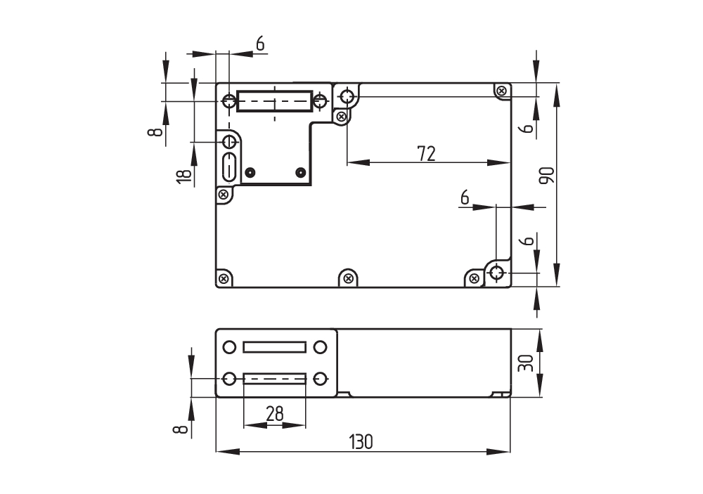
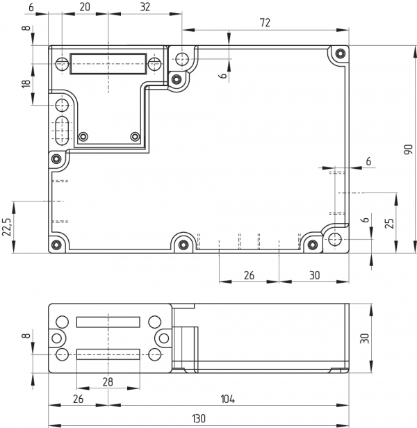
機械的データ - 寸法
| センサー長 |
30 mm |
| センサーの幅 |
130 mm |
| センサーの高さ |
90 mm |
環境条件
| 保護等級 |
IP67 |
| Ambient temperature |
-30 ... +60 °C |
| Storage and transport temperature |
-30 ... +85 °C |
| Note (Relative humidity) |
non-condensing non-icing |
| Protection class |
II |
| Permissible installation altitude above sea level, maximum |
2,000 m |
環境条件 - 絶縁値
| 定格絶縁電圧 |
250 VAC |
| 定格インパルス耐電圧 |
4 kV |
電気的データ
| 熱試験電流 |
6 A |
| 定格制御電圧 |
110 VAC 230 VAC |
| EN 60947-5-1 に基づく要求定格短絡電流 |
1,000 A |
| 消費電力、最大 |
10 W |
| スイッチ素子 |
NO 接点、NC 接点 |
| スイッチ原理 |
スローアクション |
| 開閉頻度 |
1,000 /h |
| 接点材質、電気的 |
銀 |
電気的データ - ソレノイド制御
| Magnet switch-on time |
100 % |
| Test pulse duration, maximum |
5 ms |
| Test pulse interval, minimum |
50 ms |
Electrical data - Safety contacts
| Voltage, Utilisation category AC-15 |
230 VAC |
| Current, Utilisation category AC-15 |
4 A |
| Voltage, Utilisation category DC-13 |
24 VDC |
| Current, Utilisation category DC-13 |
2.5 A |
Electrical data - Auxiliary contacts
| Voltage, Utilisation category AC-15 |
230 VAC |
| Current, Utilisation category AC-15 |
4 A |
| Voltage, Utilisation category DC-13 |
24 VDC |
| Current, Utilisation category DC-13 |
2.5 A |
その他のデータ
| 注意 (アプリケーション) |
スライド式ガード 取り外し可能なガード ヒンジ式ガード |
Note about the safety classification
- Safety classification of the interlocking function
Basically suitable up to Cat. 1 / PL c.
With 2-channel usage with fault exclusion mechanism (if a fault exclusion to the 1-channel mechanics is authorised) and suitable logic applicable up to Cat. 3 / PL d

(Determined values can vary depending on the application-specific parameters hop, dop and tcycle as well as the load.)
If multiple safety components are wired in series, the Performance Level to EN ISO 13849-1 will be reduced due to the restricted error detection under certain circumstances.
- Safety classification of the guard locking function
If the device is used as an interlock for personal safety, a safety classification of the guard locking function is required. When classifying the interlock function, a distinction must be made between monitoring of the interlock function (locking function) and controlling the unlocking function. The following safety classification of the unlocking function is based on the application of the principle of safety energy disconnection for the solenoid supply.
- The classification of the unlocking function is only valid for devices with monitored guard locking function and in the power to unlock version (see ordering code).
A fault exclusion for the guard locking function can be assumed by an external safety energy disconnection. In this case, the guard locking function does not have an effect on the failure probability of the unlock function. The safety level of the unlock function is determined exclusively by the external safety power shutdown.
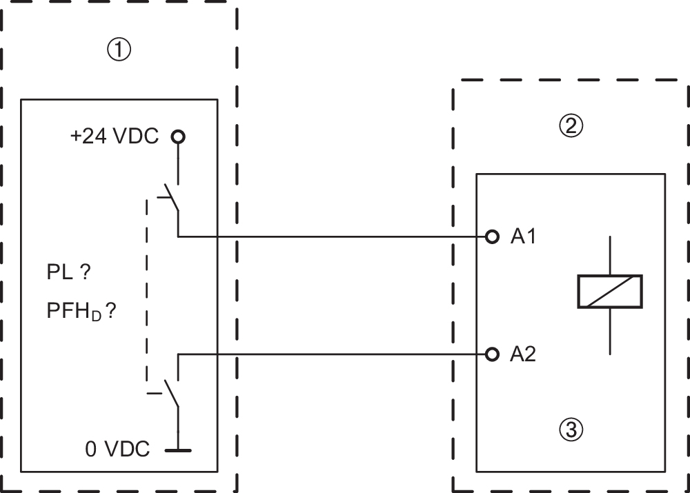
| Legend | |
|---|---|
| ¢ | Safety power shutdown |
| ƒ | Solenoid interlock |
| ¥ | Guard locking function |
- Fault exclusion with regard to wiring routing must be observed.
- If for a certain application the power to unlock version of a solenoid interlock cannot be used, for this exception an interlock with power to lock can be used if additional safety measure need to be realised that have an equivalent safety level.
UL notice
- Use Type 4X (Indoor Use) and 12 connector fittings. Tightening torque rating: 4.4 lb in.
3 Mounting
3.1 General mounting instructions
- Please observe the remarks of the standards EN ISO 12100, EN ISO 14119 and EN ISO 14120.
Three mounting holes are provided for fixing the enclosure. The solenoid interlock is double insulated. The use of an earth wire is not authorised. The solenoid interlock must not be used as an end stop. Any mounting position. The mounting position however must be chosen so that the ingress of dirt and soiling in the used opening is avoided. Unused actuator openings must be sealed with slot sealing plugs.
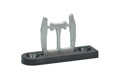
- The actuator must be permanently fitted to the safety guards and protected against displacement by suitable measures (tamperproof screws, gluing, drilling of the screw heads).
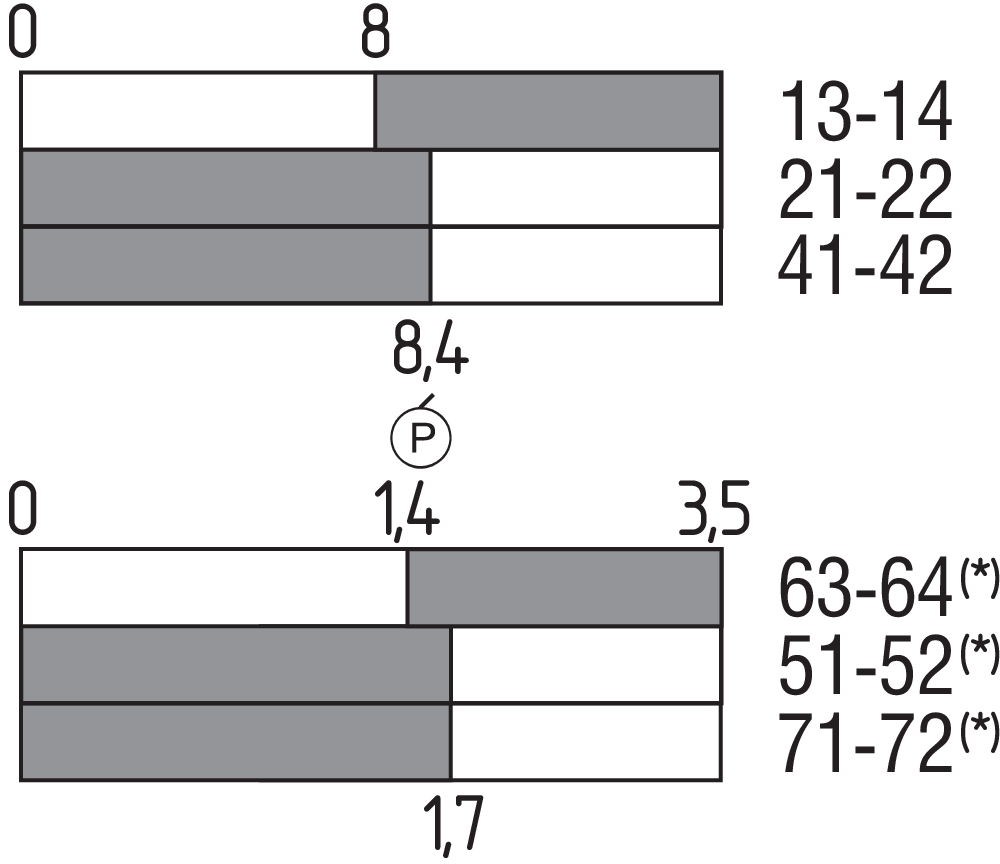
3.2 Dimensions
All measurements in mm.
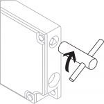
3.3 Manual release
(for set-up, maintenance, etc.)
Manual release is realised by turning the triangular key by 180° (M5 triangular key available as accessory), so that the locking bolt is pulled into the unlocking position. Please ensure that jamming by external influence on the actuator is avoided. The normal locking function is only restored after the triangular key has been returned to its original position. After being put into operation, the manual release must be secured by installing the plastic cover, which is included in delivery.
| Lateral manual release | Manual release on the cover side or on the rear side (ordering suffix -ED/-EU) |
 |  |
Triangular key TK-M5 (101100887) available as accessory.
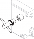
3.4 Emergency release (ordering suffix -N)
(Fitting and actuation only from outside the hazardous area)
- The emergency release should only be used in an emergency. The solenoid interlock should be installed and/or protected so that an inadvertent opening of the interlock by an emergency release can be prevented. The emergency release must be clearly labelled that it should only be used in an emergency. The label can be used that was included in the delivery.
To activate the emergency release in case of an emergency, the orange lever must be turned to the stop in the direction marked by the arrow. In this position, the safety guard can be opened. The lever is latched and cannot be returned to its original position. To cancel the blocking condition, the central mounting screw must be loosened to such extent that the lever can be turned back into its original position. The screw must then be re-tightened.
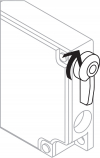
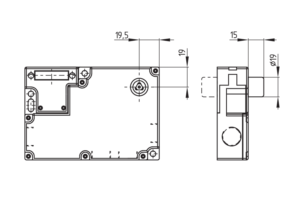
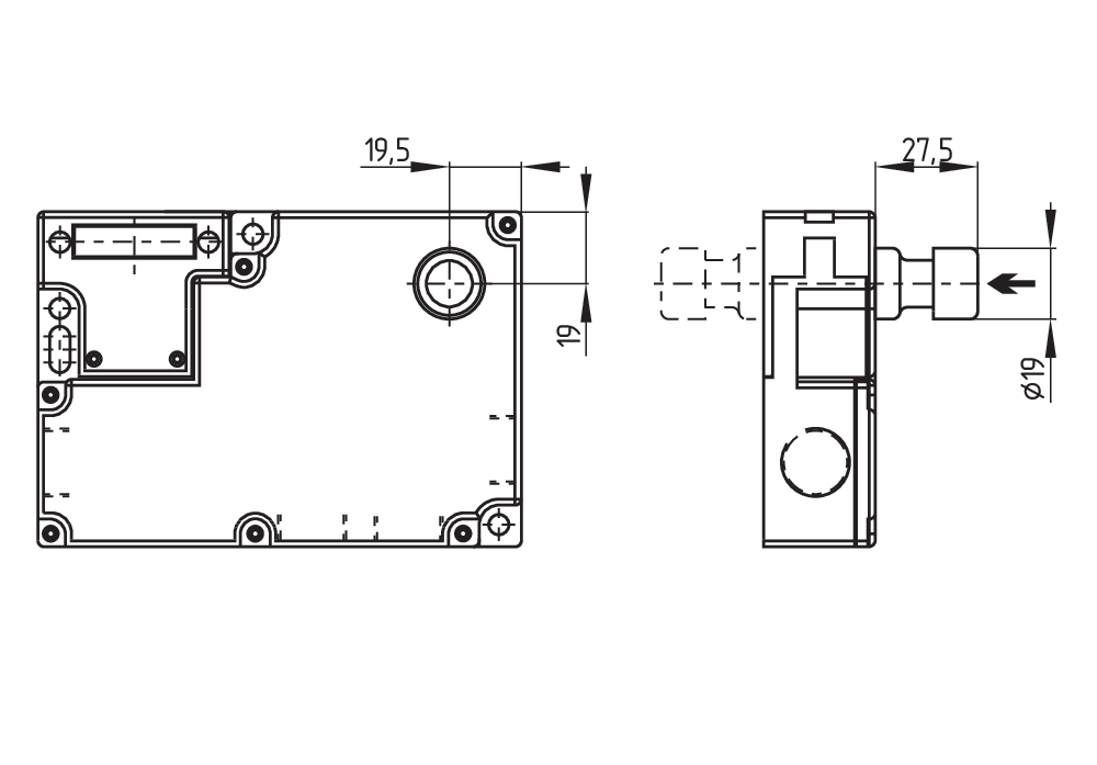
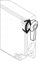
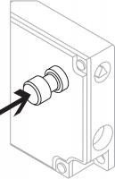
3.5 Emergency Exit
(Fitting and actuation only from within the hazardous area)
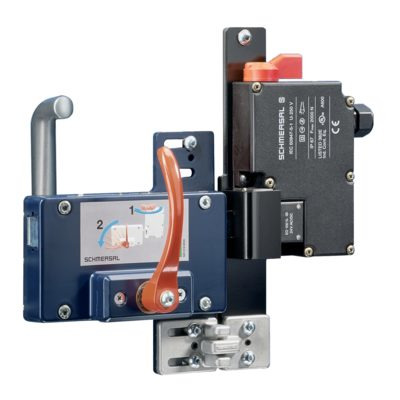
To activate the emergency exit of the T version in case of an emergency, the orange lever must be turned to the stop in direction marked by the arrow. The emergency exit function of the TD and TU versions is activated by pressing the red pushbutton. In this position, the safety guard can be opened. The blocking condition is cancelled by turning the lever in opposite direction or by pulling back the pushbutton. In unlocked position, the safety guard is protected against unintentional closing.
| Lateral emergency exit (ordering suffix -T) | Emergency exit on the cover side or on the rear side (ordering suffix -TD/-TU) |
 |  |
4 Electrical connection
4.1 General information for electrical connection
- The electrical connection may only be carried out by authorised personnel in a de-energised condition.
- If the risk analysis indicates the use of a monitored interlock they are to be connected in the safety circuit with the contacts indicated with the symbol >.
Appropriate cable glands with a suitable degree of protection are to be used. Remove the walls of the mounting holes by inserting the cable entry. All plastic residues must be removed from the switch compartment.

- Puncturing the wall of the holes with auxiliary tools (e.g. screwdriver) can cause damage.
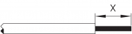
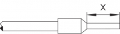
Settle length x of the conductor:
- on cage clamps (CC) of type s or f: 5 ... 6 mm
- on screw terminals (SK): 7 mm
 |  |
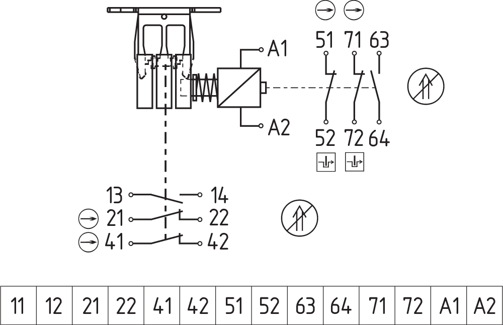
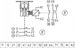
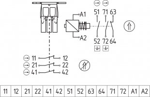
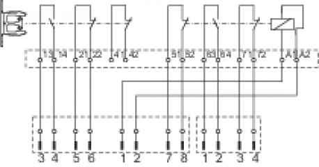
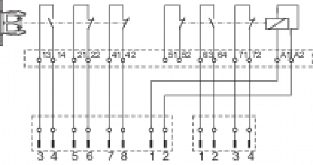
4.2 Contact Options
Contacts shown in a de-energised condition and with the actuator inserted.
| Power to unlock | Power to lock |
|---|---|
| AZM 161SK-12/12... und AZM 161CC-12/12... | |
 |  |
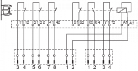
| AZM 161SK-12/03... und AZM 161CC-12/03... | |
 |  |
| Key | |
|---|---|
| B | Positive break NC contact |
| > | Monitoring the interlock according to EN ISO 14119 |
| H | Actuated |
| I | Not actuated |
| AZM 161ST-../.. with connector AZM 161ST-12/11... | AZM 161ST-11/12... |
 |  |
| AZM 161ST-11/03... | |
 |

Integrated contact kit 12/12 G (with LED)
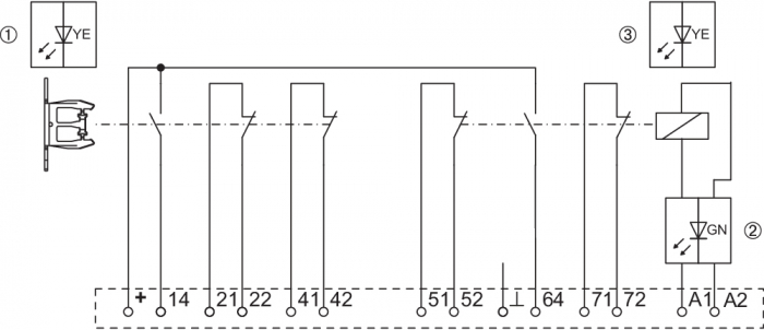
The 24 V are led internally to contacts 13 and 63. The corresponding signals of the LED display can also be tapped at terminals 14 or 64.
Integrated contact kit 12/03 G (with LED)

The 24 V are led internally to contacts 11 and 63. The corresponding signals of the LED display can also be tapped at terminals 12 or 64.
| Legend | |
|---|---|
| 1 | Door closed |
| 2 | Solenoid on |
| 3 | Door locked |
| Power to unlock | ||||
|---|---|---|---|---|
| System condition | Magnet control | LED | ||
| Power to unlock | yellow ¢ | red ƒ | yellow ¥ | |
| Door open | 24 V (0 V) | Off | On | Off |
| Door closed, actuator inserted, not locked | 24 V | On | On | Off |
| Door closed, actuator inserted and locked | 0 V | On | Off | On |
| Power to lock | ||||
|---|---|---|---|---|
| System condition | Magnet control | LED | ||
| Power to lock | yellow ¢ | red ƒ | yellow ¥ | |
| Door open | 0 V (24 V) | Off | Off | Off |
| Door closed, actuator inserted, not locked | 0 V | On | Off | Off |
| Door closed, actuator inserted and locked | 24 V | On | On | On |
5 Set-up and maintenance
The safety function of the safety components must be tested. In the case of correct installation and adequate use, the safety switchgear features maintenance-free functionality. A regular visual inspection and functional test, including the following steps, is recommended:
- Check fixation of the safety switch and the actuator.
- Fitting and integrity of the cable connections.
- Remove particles of dust and soiling.
- Adequate measures must be taken to ensure protection against tampering either to prevent tampering of the safety guard, for instance by means of replacement actuators.
- Damaged or defective components must be replaced.
6 Disassembly and disposal
6.1 Disassembly
The safety switchgear must be disassembled in a de-energised condition only.
6.2 Disposal
- The safety switchgear must be disposed of in an appropriate manner in accordance with the national prescriptions and legislations.
| EU-Konformitätserklärung |  |
| Original | K.A. Schmersal GmbH & Co. KG Möddinghofe 30 42279 Wuppertal Germany Internet: www.schmersal.com |
| Erklärung: | Hiermit erklären wir, dass die nachfolgend aufgeführten Bauteile aufgrund der Konzipierung und Bauart den Anforderungen der unten angeführten Europäischen Richtlinien entsprechen. |
| Bezeichnung des Bauteils: | AZM 161 |
| Typ: | siehe Typenschlüssel |
| Beschreibung des Bauteils: | Verriegelung mit elektromagnetischer Zuhaltung für Sicherheitsfunktionen |
| Einschlägige Richtlinien: | Maschinenrichtlinie | 2006/42/EG |
| EMV-Richtlinie | 2014/30/EU | |
| RoHS-Richtlinie | 2011/65/EU |
| Angewandte Normen: | EN 60947-5-1:2017 + AC:2020 EN ISO 14119:2013 |
| Bevollmächtigter für die Zusammenstellung der technischen Unterlagen: | Oliver Wacker Möddinghofe 30 42279 Wuppertal |
| Ort und Datum der Ausstellung: | Wuppertal, 23. August 2023 |
 |
| Rechtsverbindliche Unterschrift Philip Schmersal Geschäftsführer |
シュメアザー株式会社, 〒222-0033 横浜市港北区新横浜3-9-5, 新横浜第3東昇ビル
データと詳細は完全にチェックされました。画像は元の画像と異なる場合があります。技術的なデータはマニュアルで見られます。技術的に変更されたり、エラーの可能性があります。
Generated on 2024/04/19 13:49