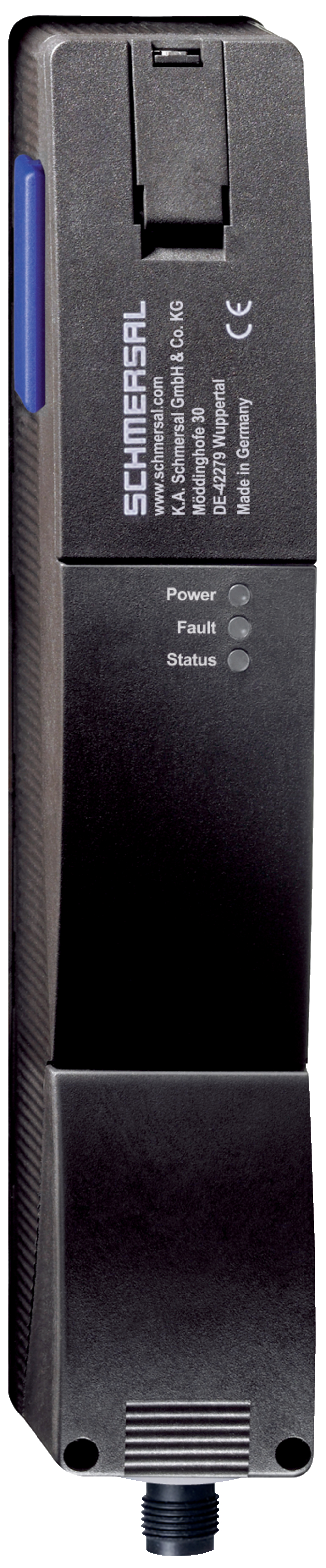
AZM201Z-I2-ST2-T-SD2P-A
| 製品タイプの説明: AZM201(1)-(2)-(3)-T-(4)-(5) |
| (1) | |
| Z | インターロック監視 |
| B | アクチュエーター監視 |
| (2) | |
| なし | 標準コード化 |
| I1 | 個別コード化 |
| I2 | 個別コード化、再ティーチング可 |
| (3) | |
| SK | ネジ端子 |
| CC | ケージクランプ式 |
| ST2 | コネクターM12, 8芯 |
| (4) | |
| 1P2PW | PNPタイプ診断出力1回路、>PNPタイプ安全出力2回路(組み合わされた診断信号: ガードシステム閉、インターロック起動) |
| SD2P | シリアル診断出力及び2 PNP安全出力 |
| (5) | |
| なし | スプリングロック |
| A | マグネットロック |
- マグネットロック
- 熱可塑性樹脂性ケース
- センサチェーンの最大長さ200m
- 自己診断機能付の31個のセンサ直列接続
- 動作状態表示用3個のLED
- センサ技術によりアクチュエータとスイッチは垂直方向± 5 mm、水平方向± 3 mmのズレが可能
- ヒンジ・スライド式扉用
- インテリジェント診断機能
- マニュアル・リリース
- 保護構造 IP66, IP67
- 高保持力 2000 N
注文データ
| Product type description |
AZM201Z-I2-ST2-T-SD2P-A |
| 部品番号(注文番号) |
103035058 |
| EAN(欧州部品番号) |
4030661537085 |
| eCl@ss number, version 12.0 |
27-27-26-03 |
| eCl@ss number, version 11.0 |
27-27-26-03 |
| eCl@ss番号、バージョン9.0 |
27-27-26-03 |
| ETIM number, version 7.0 |
EC002593 |
| ETIM number, version 6.0 |
EC002593 |
認証
| 証明書 |
TÜV cULus FCC IC ANATEL |
一般データ
| 規格 |
EN ISO 13849-1 EN ISO 14119 EN IEC 60947-5-3 EN IEC 61508 |
| 一般情報 |
個別コード化 複数のティーチング |
| Coding level according to EN ISO 14119 |
High |
| アクティブ原理 |
RFID |
| Frequency band RFID |
125 kHz |
| Transmitter output RFID, maximum |
-6 dB/m |
| ハウジング 材質 |
グラスファイバー強化熱可塑性樹脂 |
| リスク持続時間、最大 |
200 ms |
| アクチュエーターの応答時間、最大 |
100 ms |
| 入力の応答時間、最大 |
1.5 ms |
| 総重量 |
595 g |
一般データ - 仕様
| マグネットロック |
Yes |
| ガードロック監視 |
Yes |
| シリアル診断 |
Yes |
| 手動解除 |
Yes |
| 短絡検出 |
Yes |
| 短絡監視 |
Yes |
| 直列接続 |
Yes |
| 安全機能 |
Yes |
| 一体型システム診断、状態 |
Yes |
| 安全接点数 |
2 |
| センサーの直列接続の数 |
31 |
安全性評価
| 規格 |
EN ISO 13849-1 EN IEC 61508 |
安全性評価 - インターロック
| Performance Level, up to |
e |
| カテゴリー |
4 |
| PFH値 |
1.90 x 10⁻⁹ /h |
| PFD値 |
1.60 x 10⁻⁴ |
| Safety Integrity Level (SIL), suitable for applications in |
3 |
| Mission time |
20 年 |
機械的データ
| 機械的寿命、最小 |
1,000,000 操作 |
| EN ISO 14119 に準拠したクロック時引抜強度 |
2,000 N |
| Note (clamping force FZh) |
1,000 N when used with the AZ/AZM201-B30 actuator, for indoor use. |
| ロック時引抜強度, 最大 |
2,600 N |
| Note (clamping force Fmax) |
1,300 N when used with the AZ/AZM201-B30 actuator, for indoor use. |
| ラッチ力 |
30 N |
| 作動速度, 最大 |
0.2 m/s |
| Type of the fixing screws |
2x M6 |
| Tightening torque of the fixing screws, maximum |
8 Nm |
| Tightening torque of the fastening screws for the housing cover, minimum |
0.7 Nm |
| Tightening torque of the fastening screws for the housing cover, maximum |
1 Nm |
| Note |
Torx T10 |
機械的データ - 電気機械式
| Length of sensor chain, maximum |
200 m |
| Note (length of the sensor chain) |
Cable length and cross-section change the voltage drop dependiing on the output current |
| Note (series-wiring) |
Unlimited number of devices, oberserve external line fusing, max. 31 devices in case of serial diagnostic SD |
| 端子 コネクター |
M12コネクター, 8芯 |
機械的データ - 寸法
| センサー長 |
50 mm |
| センサーの幅 |
40 mm |
| センサーの高さ |
220 mm |
環境条件
| 保護等級 |
IP67 IP66 |
| Ambient temperature |
-25 ... +60 °C |
| Storage and transport temperature |
-25 ... +85 °C |
| 相対湿度, 最大 |
93 % |
| Note (Relative humidity) |
non-condensing non-icing |
| EN 60068-2-6に基づく耐振動 |
10 ~ 150 Hz、振幅 0.35 mm |
| 耐衝撃 |
30 g / 11 ms |
| Protection class |
III |
| Permissible installation altitude above sea level, maximum |
2,000 m |
環境条件 - 絶縁値
| 定格絶縁電圧 |
32 VDC |
| 定格インパルス耐電圧 |
0.8 kV |
| Overvoltage category |
III |
| VDE 0100に準拠した汚染度 |
3 |
電気的データ
| Operating voltage |
24 VDC -15 % / +10 % |
| No-load supply current I0, typical |
50 mA |
| Current consumption with magnet ON, average |
200 mA |
| Current consumption with magnet ON, peak |
700 mA / 100 ms |
| Rated operating voltage |
24 VDC |
| 動作電流 |
1,200 mA |
| EN 60947-5-1 に基づく要求定格短絡電流 |
100 A |
| External wire and device fuse rating |
2 A gG |
| 準備時間、最大 |
4,000 ms |
| 開閉頻度、最大 |
1 Hz |
| 電気的ヒューズ定格、最大 |
2 A |
電気的データ - ソレノイド制御
| Designation, Magnet control |
IN |
| マグネット入力のスイッチングの閾値 |
-3 V … 5 V (Low) 15 V … 30 V (High) |
| Magnet switch-on time |
100 % |
| Test pulse duration, maximum |
5 ms |
| Test pulse interval, minimum |
40 ms |
| Classification ZVEI CB24I, Sink |
C0 |
| Classification ZVEI CB24I, Source |
C1 C2 C3 |
Electrical data - Safety digital inputs
| Designation, Safety inputs |
X1 and X2 |
| フェイルセーフ入力のスイッチングの閾値 |
−3 V … 5 V (Low) 15 V … 30 V (High) |
| 24Vの時の安全入力の消費電流 |
5 mA |
| Test pulse duration, maximum |
1 ms |
| Test pulse interval, minimum |
100 ms |
| Classification ZVEI CB24I, Sink |
C1 |
| Classification ZVEI CB24I, Source |
C1 C2 C3 |
Electrical data - Safety digital outputs
| Designation, Safety outputs |
Y1 and Y2 |
| 定格動作電流(安全出力) |
250 mA |
| 安全出力 |
short-circuit proof, p-type |
| Voltage drop Ud, maximum |
2 V |
| Leakage current Ir, maximum |
0.5 mA |
| Voltage, Utilisation category DC-13 |
24 VDC |
| Current, Utilisation category DC-13 |
0.25 A |
| Test pulse interval, typical |
1000 ms |
| Test pulse duration, maximum |
0.5 ms |
| Classification ZVEI CB24I, Source |
C2 |
| Classification ZVEI CB24I, Sink |
C1 C2 |
Electrical data - Serial diagnostic SD
| Designation, Serial diagnostic SD |
OUT |
| Operation current |
150 mA |
| Design of control elements |
short-circuit proof, p-type |
| Wiring capacitance |
50 nF |
状態表示
| Note (LED switching conditions display) |
Operating condition: LED green Error / functional defect: LED red Supply voltage UB: LED green |
ピン配列
| PIN 1 |
A1 Supply voltage UB |
| PIN 2 |
X1 Safety input 1 |
| PIN 3 |
A2 GND |
| PIN 4 |
Y1 Safety output 1 |
| PIN 5 |
OUT serial diagnostic output |
| PIN 6 |
X2 Safety input 2 |
| PIN 7 |
Y2 Safety output 2 |
| PIN 8 |
IN serial diagnostic input |
納入品目
| 納入時同梱 |
Actuator must be ordered separately. AZM 201用三角キー |
付属品
| 推奨(アクチュエーター) |
AZ/AZM201-B1 AZ/AZM201-B30 |
Note
| Note (General) |
As long as the actuating unit remains inserted in the solenoid interlock, the unlocked safety guard can be relocked. In this case, the safety outputs are re-enabled, so that the safety guard must not be opened. |
言語フィルター
データシート
Operating Instructions and Declaration of Conformity (Short)
TÜV certification
UL Certificate
ANATEL certification
Brochure
SISTEMA-VDMA library
Adobe Readerの最新版をダウンロードしてください
Product picture (catalogue individual photo)
Dimensional drawing basic component
Video ID: AZM200-Intro
多様な取り付けオプション (Vimeo)

Video ID: AZM200-Montage1
緊急ロック解除機器のない取り付け (Vimeo)
Video ID: AZM200-Montage2
緊急ロック解除機器のある取り付け (Vimeo)
Video ID: AZM200-Betrieb2
緊急ロック解除機器 (Vimeo)
Video ID: AZM200-Betrieb3
制御された遮断工程を伴う交差短絡故障 (Vimeo)
Video ID: AZM200-Anschluss1
単一機器接続 (Vimeo)
Video ID: AZM200-Anschluss2
直列接続 (Vimeo)
Video ID: AZM200-Betrieb1
Standard Betrieb (Vimeo)
103011415 A-K8P-M12-S-G-2,5M-BK-2-X-A-4-69
- 2,5 m
- 接続ケーブル
- 8芯
103007358 A-K8P-M12-S-G-5M-BK-2-X-A-4-69
- 5 m
- 接続ケーブル
- 8芯
103007359 A-K8P-M12-S-G-10M-BK-2-X-A-4-69
- 10 m
- 接続ケーブル
- 8芯
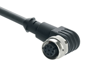
103043110 A-K8P-M12-S-W-2,5M-BK-2-X-A-4
- アングル
- 2,5 m
- 接続ケーブル
- 8芯
103043119 A-K8P-M12-S-W-5M-BK-2-X-A-4
- アングル
- 5 m
- 接続ケーブル
- 8芯
103043120 A-K8P-M12-S-W-10M-BK-2-X-A-4
- アングル
- 10 m
- 接続ケーブル
- 8芯
103043121 A-K8P-M12-S-W-15M-BK-2-X-A-4
- アングル
- 15 m
- 接続ケーブル
- 8芯

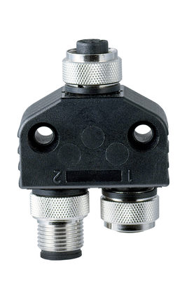
101209414 CSS-Y-A-8P
- 直列診断ケーブル付直列切断付属品
- 接続プラグは、動作電圧付セーフティケーブルを管理します。
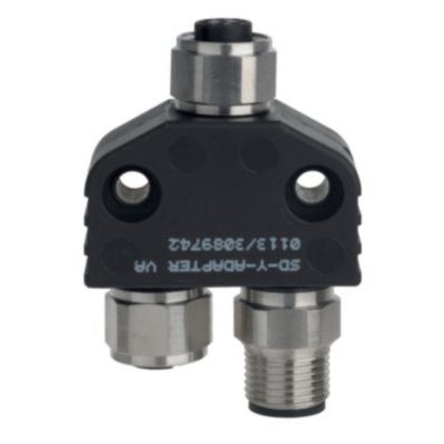
103008718 CSS-Y-A-8P-VA
- 直列診断ケーブル付直列切断付属品
- 接続プラグは、動作電圧付セーフティケーブルを管理します。
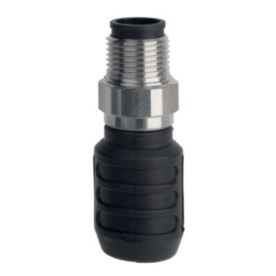
103009361 SD-Y-POWER
- 直列診断ケーブル付直列切断付属品
103009362 SD-Y-POWER VA
- 直列診断ケーブル付直列切断付属品
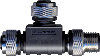
101190026 CSS-T
- 直列診断ケーブル付直列切断付属品
- 該当 センサ

101190025 CSS-T-A
- 直列診断ケーブル付直列切断付属品
- 該当 CSS 34

101209416 CSS-Y-8P
- 直列診断ケーブル付直列切断付属品
103008717 CSS-Y-8P-VA
- 直列診断ケーブル付直列切断付属品
103013493 AZ/AZM201-B1-LT
- 左スライドドア用
- バネ組み込みのアクチュエータ
- スライド式保護装置のアクチュエータ
- 最大5mmまでのオーバートラベル
103013496 AZ/AZM201-B1-LTP0
- 左スライドドア用
- 付 緊急脱出
- バネ組み込みのアクチュエータ
- スライド式保護装置のアクチュエータ
- 最大5mmまでのオーバートラベル
103013494 AZ/AZM201-B1-RT
- 右ヒンジドア用
- バネ組み込みのアクチュエータ
- スライド式保護装置のアクチュエータ
- 最大5mmまでのオーバートラベル
103013495 AZ/AZM201-B1-RTP0
- 右ヒンジドア用
- 付 緊急脱出
- バネ組み込みのアクチュエータ
- スライド式保護装置のアクチュエータ
- 最大5mmまでのオーバートラベル
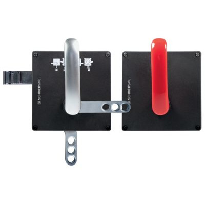
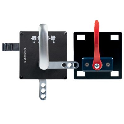
103013501 AZ/AZM201-B30-LTAG1
- 左スライドドア用
- 付 ハンドル
- ヒンジ式保護装置のアクチュエータ
- 簡素かつ直観作動
- 従来のアクチュエータでの傷害の危険性なし。
- 追加ドアハンドル不要
- 扉通り抜け時に突き出し無
103013498 AZ/AZM201-B30-LTAG1P1
- 左スライドドア用
- ヒンジ式保護装置のアクチュエータ
- 簡素かつ直観作動
- 従来のアクチュエータでの傷害の危険性なし。
- 追加ドアハンドル不要
- 扉通り抜け時に突き出し無
103013500 AZ/AZM201-B30-LTAG1P1-SZ
- 左スライドドア用
- 内蔵されたロックアウトタグ付き
- ヒンジ式保護装置のアクチュエータ
- 簡素かつ直観作動
- 従来のアクチュエータでの傷害の危険性なし。
- 追加ドアハンドル不要
- 扉通り抜け時に突き出し無
103026322 AZ/AZM201-B30-LTAG1P20-SZ
- 内蔵されたロックアウトタグ付き
- 追加ドアハンドル不要
- 左スライドドア用
- 簡素かつ直観作動
- 扉通り抜け時に突き出し無
- ヒンジ式保護装置のアクチュエータ
- 従来のアクチュエータでの傷害の危険性なし。
103015820 AZ/AZM201-B30-LTAG1P30
- 左スライドドア用
- 付 ハンドル
- ヒンジ式保護装置のアクチュエータ
- 簡素かつ直観作動
- 従来のアクチュエータでの傷害の危険性なし。
- 追加ドアハンドル不要
- 扉通り抜け時に突き出し無
103015821 AZ/AZM201-B30-LTAG1P31
- 左スライドドア用
- ヒンジ式保護装置のアクチュエータ
- 簡素かつ直観作動
- 従来のアクチュエータでの傷害の危険性なし。
- 追加ドアハンドル不要
- 扉通り抜け時に突き出し無
103015822 AZ/AZM201-B30-LTAG1P31-SZ
- 左スライドドア用
- 内蔵されたロックアウトタグ付き
- ヒンジ式保護装置のアクチュエータ
- 簡素かつ直観作動
- 従来のアクチュエータでの傷害の危険性なし。
- 追加ドアハンドル不要
- 扉通り抜け時に突き出し無
103013502 AZ/AZM201-B30-RTAG1
- 右ヒンジドア用
- 付 ハンドル
- ヒンジ式保護装置のアクチュエータ
- 簡素かつ直観作動
- 従来のアクチュエータでの傷害の危険性なし。
- 追加ドアハンドル不要
- 扉通り抜け時に突き出し無
103013497 AZ/AZM201-B30-RTAG1P1
- 右ヒンジドア用
- ヒンジ式保護装置のアクチュエータ
- 簡素かつ直観作動
- 従来のアクチュエータでの傷害の危険性なし。
- 追加ドアハンドル不要
- 扉通り抜け時に突き出し無
103013499 AZ/AZM201-B30-RTAG1P1-SZ
- 右ヒンジドア用
- 内蔵されたロックアウトタグ付き
- ヒンジ式保護装置のアクチュエータ
- 簡素かつ直観作動
- 従来のアクチュエータでの傷害の危険性なし。
- 追加ドアハンドル不要
- 扉通り抜け時に突き出し無
103026321 AZ/AZM201-B30-RTAG1P20-SZ
- 内蔵されたロックアウトタグ付き
- 追加ドアハンドル不要
- 右ヒンジドア用
- 簡素かつ直観作動
- 扉通り抜け時に突き出し無
- ヒンジ式保護装置のアクチュエータ
- 従来のアクチュエータでの傷害の危険性なし。
103015823 AZ/AZM201-B30-RTAG1P30
- 右ヒンジドア用
- 付 ハンドル
- ヒンジ式保護装置のアクチュエータ
- 簡素かつ直観作動
- 従来のアクチュエータでの傷害の危険性なし。
- 追加ドアハンドル不要
- 扉通り抜け時に突き出し無

103015824 AZ/AZM201-B30-RTAG1P31
- 右ヒンジドア用
- ヒンジ式保護装置のアクチュエータ
- 簡素かつ直観作動
- 従来のアクチュエータでの傷害の危険性なし。
- 追加ドアハンドル不要
- 扉通り抜け時に突き出し無
103015825 AZ/AZM201-B30-RTAG1P31-SZ
- 右ヒンジドア用
- 内蔵されたロックアウトタグ付き
- ヒンジ式保護装置のアクチュエータ
- 簡素かつ直観作動
- 従来のアクチュエータでの傷害の危険性なし。
- 追加ドアハンドル不要
- 扉通り抜け時に突き出し無

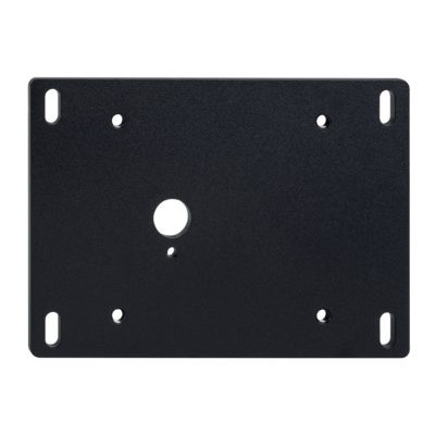
101188600 MOUNTING PLATE AZ/AZM200
- Mounting plate for easy and quick assembly
- Metal, powder-coated
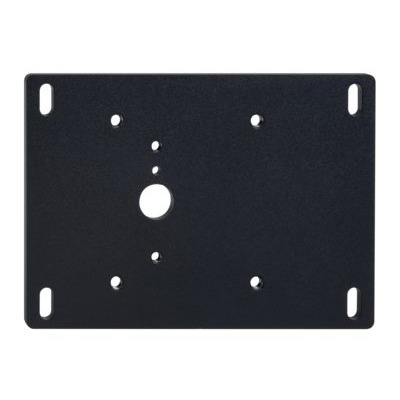
101194218 MOUNTING PLATE MP AZ/AZM200-B30
- Mounting plate for easy and quick assembly
- Metal, powder-coated
- suitable for left and right hinged doors
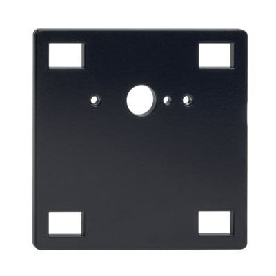
101194224 MOUNTING PLATE MP AZ/AZM200-P1
- Mounting plate for easy and quick assembly
- Metal, powder-coated
- suitable for left and right hinged doors
101185694 MOUNTING PLATE MP AZ/AZM200-P20
- Mounting plate for easy and quick assembly
- Metal, powder-coated
- suitable for left and right hinged doors
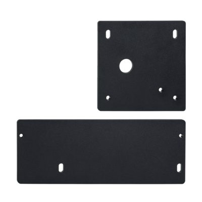
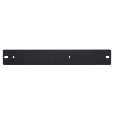
101214126 MONTAGEPLATTEN KPL. MP BDF 200
- Mounting plate for easy and quick assembly
- Metal, powder-coated
- suitable for left and right hinged doors
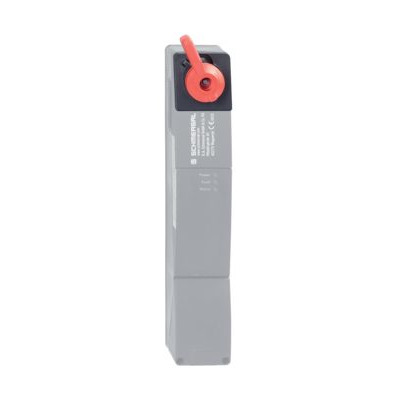
103003543 RF-AZM200/201-N
- Emergency release retrofit kit
- Subsequent functional expansion of the solenoid interlock AZM200 / AZM201
- optional lead sealing possible
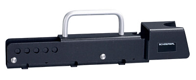
103004966 RF-AZM200/201-T
- Subsequent functional expansion of the solenoid interlock AZM200 / AZM201
- Emergency exit retrofit kit
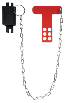
101194438 Lockout tag SZ 200
- 5個の穴付ロックアウト・タグ
- 危険領域の内部・外部の取り付けに適切
- 取り付け作業などの予期可能な「閉」防止
- 複合設備用
- スイッチ動作防止
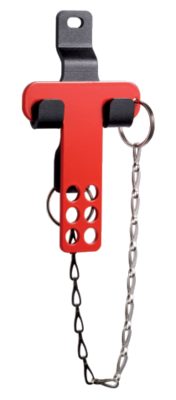
101196397 LOCKOUT TAG SZ 200-1
- 6個の穴付ロックアウト・タグ
- 危険領域の内部・外部の取り付けに適切
- 取り付け作業などの予期可能な「閉」防止
- 複合設備用
- スイッチ動作防止
103051655 SZ201-1
- 危険領域の内部・外部の取り付けに適切
- 取り付け作業などの予期可能な「閉」防止
- 複合設備用
- スイッチ動作防止
- 6個の穴付ロックアウト・タグ

103009970 SRB-E-201LC
- STOP 0 機能
- 1 oder 2チャンネルコントロール
- リセットボタン / 自動リセット
- 2 安全出力 2 A
- 1 補助出力

103007672 SRB-E-301ST
- STOP 0 機能
- 1 oder 2チャンネルコントロール
- リセットボタン / 自動リセット
- 1 補助接点
- 3 安全出力

103009973 SRB-E-204ST
- STOP 0 機能
- 4 センサーの監視
- リセットボタン / 自動リセット
- 2 安全出力
- 4 補助出力
Table of Contents
- 1 この文書について
- 1.1 機能
- 1.2 対象: 権限 資格のある人向け
- 1.3 使用記号の説明
- 1.4 適切な使用
- 1.5 安全上のご注意
- 2 製品内容
- 2.1 型番
- 2.2 特殊仕様
- 2.3 目的
- 2.4 誤使用に関する警告
- 2.5 免責事項
- 2.6 技術データ
- 3 取り付け
- 3.1 通常の取り付け方法
- 3.2 外形図
- 4 電気配線
- 4.1 電気配線上のご注意
- 4.3 Serial diagnostic -SD
- 4.4 Wiring examples for series-wiring
- 5 アクチュエータのティーチング / アクチュエータ検出
- 6 動作原理と診断機能
- 6.1 ソレノイド制御
- 6.2 バージョン毎の安全出力の動作
- 6.3 診断用LED
- 6.4 診断出力・電磁ロック付きインターロック
- 6.5 直列診断機能SD付き電磁ロック付きインターロック
- 7 セットアップとメンテナンス
- 8 取り外し・廃棄
- 8.1 取り外し
- 8.2 廃棄処分
- 9 Appendix – Special versions
1 この文書について
1.1 機能
本書は、本製品の安全な操作と解体のために、取付け、セットアップ、試運転に必要なすべての情報を提供します。取扱説明書は、完全な状態で、常にアクセスしやすい場所に保管してください。
1.2 対象: 権限 資格のある人向け
この取扱説明書に記述された全ての操作は、使用者によって認められた専門技術者が行ってください。
この取扱説明書を熟読し、コンポーネントの据付及び運転の前に、労働安全及び事故予防のための適用可能な全規定に付いてご確認ください。
機械製造者は、準拠すべき整合規格や、部品の選択、取り付け、インテグレーションに関するその他の技術仕様を慎重に選択する必要があります。
仕様などの記載内容について予告なく変更する事があります。あらかじめご了承ください
1.3 使用記号の説明
- 情報、助言、注釈:この表示は役立つ追加情報を示します。
- 注意: 取り扱いを誤った場合に、故障、機能不良が想定される内容を示しています。
警告:取り扱いを誤った場合に、傷害を負う可能性が想定される内容、及び物的損害の発生が想定される内容を示しています。
1.4 適切な使用
シュメアザールが提供する製品は、個人消費者向けではありません。
本製品は、設備や機械の一部として安全関連機能を果たすために開発されたものです。 機械や設備全体が正しく機能することを保証することは、機械や設備の製造者の責任です。
セーフティスイッチは下記に挙げられたバージョン、又は製造者によって許可されたアプリケーションに対してのみ使用しなければなりません。アプリケーションの範囲に関する詳細は、「製品内容」の項を参照ください。
1.5 安全上のご注意
ユーザーはこの取扱説明書に記載されている、安全上の説明、各国の設置基準、並びに全ての周知の安全規則や事故防止規則を遵守しなければなりません。
- 詳細な技術情報に付いてはSchmersalカタログ、又はインターネット(products.schmersal.com)上のオンラインカタログをご参照下さい。
2 製品内容
2.1 型番
| 製品タイプの説明: AZM201(1)-(2)-(3)-T-(4)-(5) |
| (1) | |
| Z | インターロック監視 |
| B | アクチュエーター監視 |
| (2) | |
| なし | 標準コード化 |
| I1 | 個別コード化 |
| I2 | 個別コード化、再ティーチング可 |
| (3) | |
| SK | ネジ端子 |
| CC | ケージクランプ式 |
| ST2 | コネクターM12, 8芯 |
| (4) | |
| 1P2PW | PNPタイプ診断出力1回路、>PNPタイプ安全出力2回路(組み合わされた診断信号: ガードシステム閉、インターロック起動) |
| SD2P | シリアル診断出力及び2 PNP安全出力 |
| (5) | |
| なし | スプリングロック |
| A | マグネットロック |
| Actuator | suitable for |
|---|---|
| AZ/AZM201-B1-... | Sliding safety guards |
| AZ/AZM201-B30-... | Hinged safety guards |
| AZ/AZM201-B40-... | Hinged-doors with overlapping folds |
2.2 特殊仕様
型式記号で挙げられていない特別仕様は一般使用に準じます。
- Special information or information deviating from the standard on special versions can be found in the concluding chapter "Appendix – Special versions".
2.3 目的
非接触式セーフティスイッチは、安全回路での用途向けに設計されており、可動ガードの位置やロック状態の監視に使用されます。
- セーフティスイッチは、EN ISO 14119に基づきタイプ4のインターロック機器に分類されます。個別コード化の仕様ではコード化レベルHighに分類されます。
電磁ロック機能及びインターロック機能付きのセーフティスイッチとして種々のタイプを使用できます。
- リスク分析の結果、監視されたインターロックの使用が必要とされる場合は、 > のシンボル付きで表示されるインターロック監視タイプの製品を使用してください。
アクチュエータ監視機種 (B) は工程保護のためのインターロック機能を持つセーフティスイッチです。
安全機能により、ガードが開いていると安全出力はOFFとなり、ガードが開いている間はOFFの状態を維持します。
- マグネットロックタイプは、電源が故障したりメインスイッチが切れたりするとロックが解除されるため、事故の危険を十分に評価した後の特殊なケースでのみ用いることができます。
直列接続ができます。直列に接続すると、追加のデバイス毎に反応時間とリスク時間が最大1.5ms増加します。コンポーネントの数は、技術データに基づく外部ケーブルヒューズ保護と、ケーブル損失によってのみ制限されます。AZM300 … SDを直列診断付きで31個まで直列接続する事が可能です。シリアル診断機能付きの機器(型式末尾-SD)では、シリアル診断接続は評価の目的で直列に接続され、SDゲートウェイに接続されます。付録の配線例をご参照ください。
- 使用者は、関連規格と要求される安全レベルに基づいてセーフティチェーンを評価し、設計しなければなりません。複数のセーフティセンサが同じセーフティ機能に関わっている場合、個々のコンポーネントの PFH 値を加算する必要があります。
- セーフティコンポーネントが組み込まれた制御システムの全体的な構想は、関連規格に対して妥当性を確認しなければなりません。
2.4 誤使用に関する警告
- 本製品の不十分、不適切な使用及び無効化の際は、人への危険、機械、設備への損害を負う可能性があります。取付、据付、操作及び保全に関する説明書と同様に安全に関する注意が遵守されていれば、残留リスクはありません。
2.5 免責事項
誤った取り付けやこの取扱説明書を正しく理解していないために起こった損害、故障は、Schmersalの免責事項となります。また、製造者に許可されていない代替・付属品による損害は、製造者の免責事項となります。
安全上の理由から、デバイスに対する独自の変更や不適切な修理、部品の交換や改造は厳として認められず、それが理由で発生した故障や事故に対し、Schmersalは責任を一切負いません。
2.6 技術データ
認証
| 証明書 |
TÜV cULus FCC IC ANATEL |
一般データ
| 規格 |
EN ISO 13849-1 EN ISO 14119 EN IEC 60947-5-3 EN IEC 61508 |
| 一般情報 |
個別コード化 複数のティーチング |
| Coding level according to EN ISO 14119 |
High |
| アクティブ原理 |
RFID |
| Frequency band RFID |
125 kHz |
| Transmitter output RFID, maximum |
-6 dB/m |
| ハウジング 材質 |
グラスファイバー強化熱可塑性樹脂 |
| リスク持続時間、最大 |
200 ms |
| アクチュエーターの応答時間、最大 |
100 ms |
| 入力の応答時間、最大 |
1.5 ms |
| 総重量 |
595 g |
一般データ - 仕様
| マグネットロック |
Yes |
| ガードロック監視 |
Yes |
| シリアル診断 |
Yes |
| 手動解除 |
Yes |
| 短絡検出 |
Yes |
| 短絡監視 |
Yes |
| 直列接続 |
Yes |
| 安全機能 |
Yes |
| 一体型システム診断、状態 |
Yes |
| 安全接点数 |
2 |
| センサーの直列接続の数 |
31 |
安全性評価
| 規格 |
EN ISO 13849-1 EN IEC 61508 |
安全性評価 - インターロック
| Performance Level, up to |
e |
| カテゴリー |
4 |
| PFH値 |
1.90 x 10⁻⁹ /h |
| PFD値 |
1.60 x 10⁻⁴ |
| Safety Integrity Level (SIL), suitable for applications in |
3 |
| Mission time |
20 年 |
機械的データ
| 機械的寿命、最小 |
1,000,000 操作 |
| EN ISO 14119 に準拠したクロック時引抜強度 |
2,000 N |
| Note (clamping force FZh) |
1,000 N when used with the AZ/AZM201-B30 actuator, for indoor use. |
| ロック時引抜強度, 最大 |
2,600 N |
| Note (clamping force Fmax) |
1,300 N when used with the AZ/AZM201-B30 actuator, for indoor use. |
| ラッチ力 |
30 N |
| 作動速度, 最大 |
0.2 m/s |
| Type of the fixing screws |
2x M6 |
| Tightening torque of the fixing screws, maximum |
8 Nm |
| Tightening torque of the fastening screws for the housing cover, minimum |
0.7 Nm |
| Tightening torque of the fastening screws for the housing cover, maximum |
1 Nm |
| Note |
Torx T10 |
機械的データ - 電気機械式
| Length of sensor chain, maximum |
200 m |
| Note (length of the sensor chain) |
Cable length and cross-section change the voltage drop dependiing on the output current |
| Note (series-wiring) |
Unlimited number of devices, oberserve external line fusing, max. 31 devices in case of serial diagnostic SD |
| 端子 コネクター |
M12コネクター, 8芯 |
機械的データ - 寸法
| センサー長 |
50 mm |
| センサーの幅 |
40 mm |
| センサーの高さ |
220 mm |
環境条件
| 保護等級 |
IP67 IP66 |
| Ambient temperature |
-25 ... +60 °C |
| Storage and transport temperature |
-25 ... +85 °C |
| 相対湿度, 最大 |
93 % |
| Note (Relative humidity) |
non-condensing non-icing |
| EN 60068-2-6に基づく耐振動 |
10 ~ 150 Hz、振幅 0.35 mm |
| 耐衝撃 |
30 g / 11 ms |
| Protection class |
III |
| Permissible installation altitude above sea level, maximum |
2,000 m |
環境条件 - 絶縁値
| 定格絶縁電圧 |
32 VDC |
| 定格インパルス耐電圧 |
0.8 kV |
| Overvoltage category |
III |
| VDE 0100に準拠した汚染度 |
3 |
電気的データ
| Operating voltage |
24 VDC -15 % / +10 % |
| No-load supply current I0, typical |
50 mA |
| Current consumption with magnet ON, average |
200 mA |
| Current consumption with magnet ON, peak |
700 mA / 100 ms |
| Rated operating voltage |
24 VDC |
| 動作電流 |
1,200 mA |
| EN 60947-5-1 に基づく要求定格短絡電流 |
100 A |
| External wire and device fuse rating |
2 A gG |
| 準備時間、最大 |
4,000 ms |
| 開閉頻度、最大 |
1 Hz |
| 電気的ヒューズ定格、最大 |
2 A |
電気的データ - ソレノイド制御
| Designation, Magnet control |
IN |
| マグネット入力のスイッチングの閾値 |
-3 V … 5 V (Low) 15 V … 30 V (High) |
| Magnet switch-on time |
100 % |
| Test pulse duration, maximum |
5 ms |
| Test pulse interval, minimum |
40 ms |
| Classification ZVEI CB24I, Sink |
C0 |
| Classification ZVEI CB24I, Source |
C1 C2 C3 |
Electrical data - Safety digital inputs
| Designation, Safety inputs |
X1 and X2 |
| フェイルセーフ入力のスイッチングの閾値 |
−3 V … 5 V (Low) 15 V … 30 V (High) |
| 24Vの時の安全入力の消費電流 |
5 mA |
| Test pulse duration, maximum |
1 ms |
| Test pulse interval, minimum |
100 ms |
| Classification ZVEI CB24I, Sink |
C1 |
| Classification ZVEI CB24I, Source |
C1 C2 C3 |
Electrical data - Safety digital outputs
| Designation, Safety outputs |
Y1 and Y2 |
| 定格動作電流(安全出力) |
250 mA |
| 安全出力 |
short-circuit proof, p-type |
| Voltage drop Ud, maximum |
2 V |
| Leakage current Ir, maximum |
0.5 mA |
| Voltage, Utilisation category DC-13 |
24 VDC |
| Current, Utilisation category DC-13 |
0.25 A |
| Test pulse interval, typical |
1000 ms |
| Test pulse duration, maximum |
0.5 ms |
| Classification ZVEI CB24I, Source |
C2 |
| Classification ZVEI CB24I, Sink |
C1 C2 |
Electrical data - Serial diagnostic SD
| Designation, Serial diagnostic SD |
OUT |
| Operation current |
150 mA |
| Design of control elements |
short-circuit proof, p-type |
| Wiring capacitance |
50 nF |
状態表示
| Note (LED switching conditions display) |
Operating condition: LED green Error / functional defect: LED red Supply voltage UB: LED green |
ピン配列
| PIN 1 |
A1 Supply voltage UB |
| PIN 2 |
X1 Safety input 1 |
| PIN 3 |
A2 GND |
| PIN 4 |
Y1 Safety output 1 |
| PIN 5 |
OUT serial diagnostic output |
| PIN 6 |
X2 Safety input 2 |
| PIN 7 |
Y2 Safety output 2 |
| PIN 8 |
IN serial diagnostic input |
安全分類について
- The safety classification of the guard locking function only applies for standard devices with monitored solenoid interlock AZM201Z-…-1P2PW-… (see Ordering code). A safety classification of the guard locking function for devices with serial diagnostics "SD2P" is not allowed due to the non-safe locking/unlocking signal from the SD Gateway
- 特定のアプリケーションで、スプリングロックタイプの電磁ロック付きインターロックが使えない時は、同等のレベルを持つ追加の安全方策が実現出来れば、例外としてマグネットロックタイプのインターロックが使えます。
- ガードロック機能の安全性分析において、電磁ロック付きインターロックAZMを完全なシステムの一部として参照しています。
障害を防止するための、安全な動作や安全な動作やケーブルの保護といった更なる方策は、ユーザー側で行わなければなりません。
ガードロックが解除されるという故障が発生した場合、これは電磁ロック付きインターロックにより検知され、安全ドアのY1/Y2がOFFします。この様な故障が発生すると、機械が安全な状態になる前に、保護機器は一度だけ直ちに開きます。カテゴリ2のシステム動作では、テストによって検知される安全機能の喪失が原因の故障がある可能性があります。
- インターロックの作動は、外部へのOSSD出力信号と比較されなければなりません。意図しないロック解除が原因でシャットダウンが発生した場合、これは外部診断によって検出されます。
UL notice
絶縁電源のみを使用してください。NFPA 79 アプリケーションでのみ使用します。フィールド配線の手段を提供するアダプターは、メーカーから入手出来ます。メーカーの情報をご参照ください。
FCC/IC - 注意
このデバイスは、FCC規則のパート15に準拠しており、またカナダのイノベーション科学経済開発省のライセンス免除RSSに準拠するライセンス免除送信機/受信機が含まれています。
操作は、次の2つの条件の下で許可されます:
(1) 本装置は有害な干渉信号を発生させてはならない。
(2)本装置は干渉信号を許容できなければならない。これらの条件には、本装置が不適切に機能する原因となる干渉信号も含まれます。
本装置は、100mm以上の距離で使用される場合、神経刺激制限(ISED SPR-002)に準拠します。K.A.Schmersal GmbH & Co.KGが明示的に承認していない変更または改造は、 装置を操作するユーザーの権限を無効にする可能性があります。
この機器に含まれる免許不要の送受信機は、免許不要の無線機器に適用されるカナダ革新 科学 経済開発(ISED)当局の「無線規格仕様」の要件を満たしています。この機器に含まれる免許不要の送受信機は、免許不要の無線機器に適用されるカナダ革新 科学 経済開発(ISED)当局の「無線規格仕様」の要件を満たしています。以下の2つの条件下で動作が許可されます:
(1) 妨害電波を発生させてはならない。
(2) 本装置は、その機能を損なう可能性がある場合であっても、受信した無線周波数の干渉を許容しなければならない。
本装置は、100mm以上の距離で使用する場合、神経刺激制限(ISED CNR-102)に適合します。
Schmersal GmbH & Co. KG が明示的に承認していない変更または改造を行った場合、 ユーザーによるデバイスの使用許可は無効になる場合があります。
| 20941-22-14519 | Este equipamento nao tem direito àprotecao contra interferência prejudicial e nao pode causar interferencia em sistemas devidamente autorizados. Para maiores informacores consultar: www.gov.br/anatel |
3 取り付け
3.1 通常の取り付け方法
- 規格ISO 12100、ISO 14119及びISO 14120の関連要求事項を遵守してください。
For fitting the safety switch and the actuator, two mounting holes for M6 screws with washers (washers included in delivery) are provided. The safety switch must not be used as end stop. Any position is possible. The mounting position however must be chosen so that the ingress of dirt and soiling in the used opening is avoided. The unused actuator opening must be sealed by means of the dust-proof flap (included in delivery).
Minimum distance between two safety switchgear
as well as to other systems with same frequency (125 kHz): 100 mm.

アクチュエータの取り付け
適合するアクチュエータの取扱説明書をご参照下さい。
- アクチュエータはガードに確実に取り付け、適切な方法(無効化防止ネジ、接着、ネジヘッドをつぶすなど)により取り外しが出来ないようにしなければなりません。
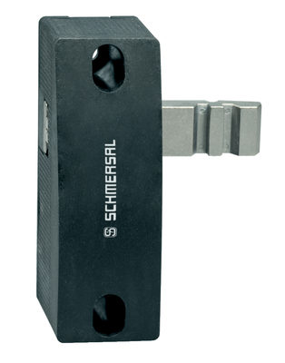
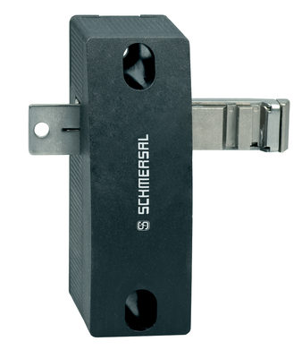
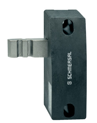
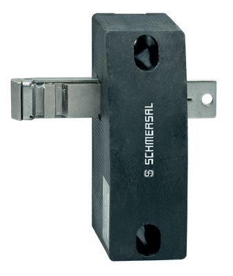
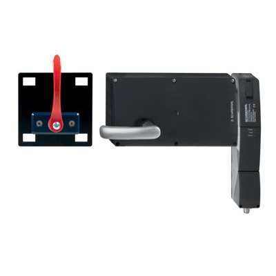
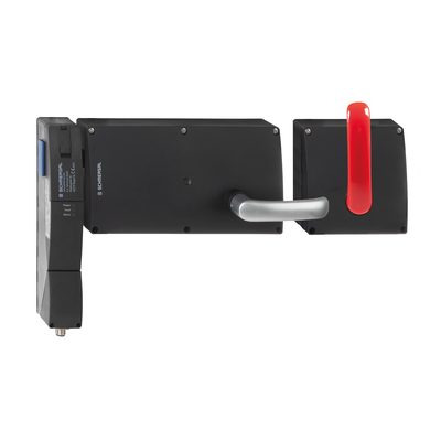
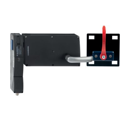
Manual release
For the machine set-up, the solenoid interlock can be unlocked in a de-energised condition. After opening of the plastic flap "A" (refer to image "Dimensions"), the triangular key must be turned clockwise to bring the blocking bolt in unlocking condition. The normal locking function is only restored after the triangular key has been returned to its original position.
- Caution: do not turn beyond the latching point, maximum tightening torque: 1.3 Nm.
After being put into operation, the manual release must be secured by closing the plastic flap "A" and affixing the seal, which is included in delivery.
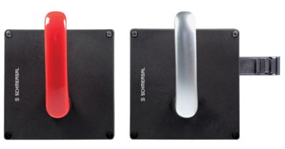
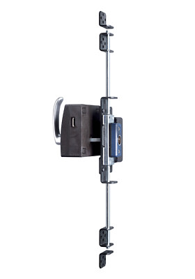
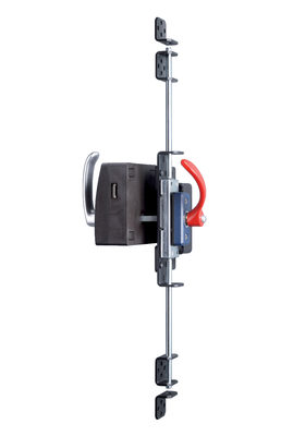
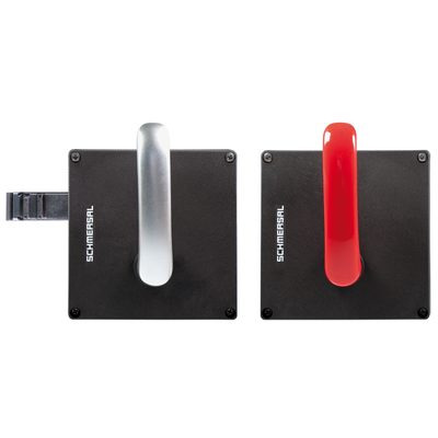
| Component ready for operation | Component not ready for operation |
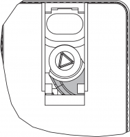 | 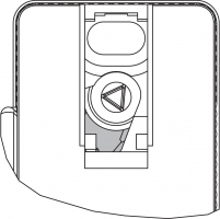 |
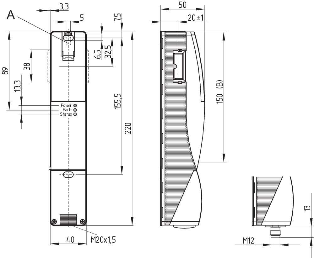
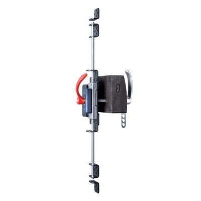
3.2 外形図
全ての寸法表記はmm
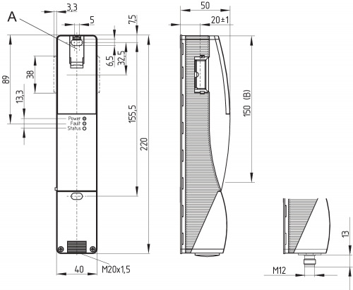
Legend
A: Manual release
B: Active RFID area
- Metal parts and magnetic fields in the lateral RFID area of the safety switchgear and the actuator can influence the switching distance or lead to malfunctions.
The retrofit kit is used for subsequent functional expansion of the solenoid interlock.
| Designation | Ordering code | |
|---|---|---|
| Emergency release | RF-AZM200-N | 103003543 |
| Emergency Exit | RF-AZM200-T | 103004966 |
4 電気配線
4.1 電気配線上のご注意
- 電気配線は専門技術者が非通電の状態で行って下さい。
The power supply must have protection against permanent overvoltage. Supply units according to EN 60204-1 is recommended.
必要なケーブルのヒューズ保護を設置時に統合する必要があります。
安全出力は制御システムの安全回路に接続出来ます。
接続するセーフティリレーユニットの要求事項:
2チャンネル安全入力で2つのPNPタイプの半導体出力に適します。
- Safety controller configuration
If the safety switchgear is connected to electronic safety-monitoring modules, we recommend that you set a discrepancy time of at least 100 ms. The safety inputs of the safety-monitoring module must be able blanking a test impulse of approx. 1 ms. The safety-monitoring module does not need to have a cross-wire short monitoring function, if necessary, the cross-wire short monitoring function must be disabled.
- 適切なセーフティリレーユニットの選択に関する情報は、Schmersalのカタログか、インターネット (products.schmersal.com) 上にあるオンラインカタログをご覧ください。
The cable entry is realised by a metric M20 gland. This gland must be dimensioned by the user so that it is suitable for the cable used. A cable gland with strain relief and suitable IP degree of protection must be used.
Settle length x of the conductor:
- on screw terminals (SK): 8 mm
- on cage clamps (CC) of type s, r or f: 7.5 mm

4.3 Serial diagnostic -SD
- The fitted 24V, X1, X2 bridge is included in the delivery of …-1P2PW and …-SD2P.
- SD機器に配線する時には、ケーブルによる電圧降下や個々のコンポーネントの電流容量に配慮してください。
- 直列接続のオプション
SDコンポーネントを便利に直列接続するために、追加のアクセサリーとして、SD接続箱PFB-SD-4M12-SD (屋外用) とPDM-SD-4CC-SD (制御盤用) が用意されています。詳しくはインターネット (products.schmersal.com) をご覧ください。
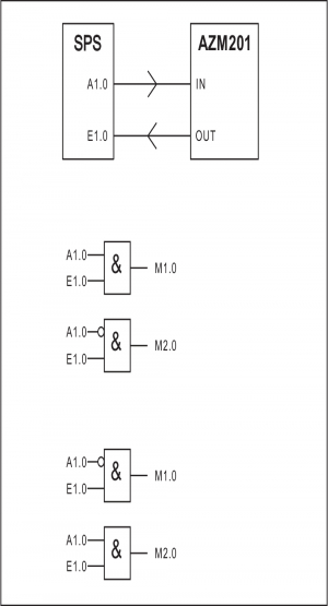
4.4 Wiring examples for series-wiring
Series-wiring can be set up. In the case of a series connection, the risk time remains unchanged and the reaction time increases by the sum of the reaction time of the inputs per additional unit specified in the technical data. The quantity of devices is only limited by the cable drops and the external cable fuse protection, according to the technical data. Series-wiring of up to 31 AZM201 … SD components with serial diagnostics is possible.
アプリケーション例を提示します。個々のアプリケーションに対して、スイッチ類やそのセットアップが適切かどうか、注意深くチェックしなければなりません。アプリケーション例を提示します。
Wiring example 1: Series wiring AZM201 with conventional diagnostic output.
In the series wiring, the 24V-X1-X2 bridge must be removed from all components up to the last component. The voltage is supplied at both safety inputs of the terminal safety component of the chain (considered from the safety-monitoring module). The safety outputs of the first safety component are wired to the safety-monitoring module.
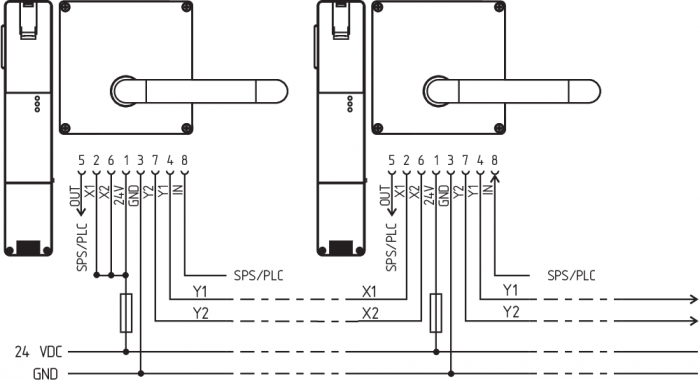
Y1 と Y2 = 安全出力 → 安全リレーユニット
Wiring example 2: Series-wiring of the AZM201 with serial diagnostic function (max. 31 components in series)
In devices with the serial diagnostics function (ordering suffix -SD), the serial diagnostics connections are wired in series and connected to a SD-Gateway for evaluation purposes. The safety outputs of the first safety component are wired to the safety-monitoring module. The serial Diagnostic Gateway is connected to the serial diagnostic input of the first safety component.

Y1 と Y2 = 安全出力 → 安全リレーユニット
SD-IN ゲートウェイ フィールドバス
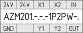
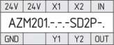
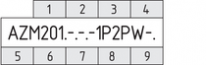
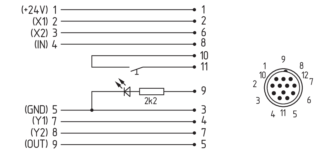
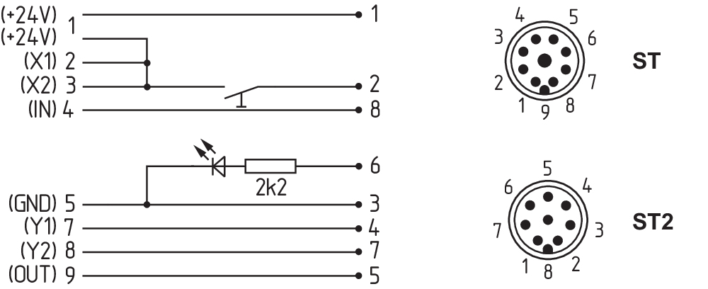
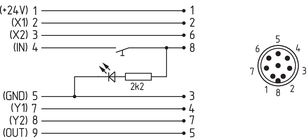
| Function safety switchgear | Pin configurationof the connector ST2, M12, 8-pole | Configuration of the removable terminal blocks | Colour codes of the Schmersal connector plugs to DIN 47100 | Poss. colour code of other commercially available connector plugs according to EN 60947-5-2 | ||
|---|---|---|---|---|---|---|
| with conventional diagnostic output | with serial diagnostic function |  | ||||
| 24V | Ue | 1 | 1 | WH | BN | |
| X1 | Safety input 1 | 2 | 2 | BN | WH | |
| GND | GND | 3 | 5 | GN | BU | |
| Y1 | Safety output 1 | 4 | 7 | YE | BK | |
| OUT | Diagnostic output | SD output | 5 | 9 | GY | GY |
| X2 | Safety input 2 | 6 | 3 | PK | PK | |
| Y2 | Safety output 2 | 7 | 8 | BU | VT | |
| IN | Magnet control | SD input | 8 | 4 | RD | OR |
| without function | - | 6 | ||||
| View Terminal block for ordering suffix -SK or -CC | View Version with removable terminal blocks | |
|---|---|---|
 |  |  |
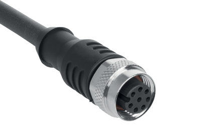
| Connecting cables with coupling (female) IP67 / IP69, M12, 8-pole - 8 x 0.25 mm² to DIN 47100 | |
|---|---|
| Cable length | Ordering code |
| 2,5 m | 103011415 |
| 5,0 m | 103007358 |
| 10,0 m | 103007359 |
| 15,0 m | 103011414 |
5 アクチュエータのティーチング / アクチュエータ検出
標準コード化された電磁ロック付きインターロックは納入後直ぐに使用できます。
個別コード化された電磁ロック付きインターロックとアクチュエータは以下のティーチング工程が必要です。
- 電磁ロック付きインターロックの電源供給を遮断し、再投入してください。
- アクチュエータを検出領域に導きます。ティーチングの手順が電磁ロック付きインターロックのLED、緑OFF、赤ON、黄色点滅(1 Hz)で示されます。
- 10秒後に黄色LEDが短い(3 Hz)点滅で、電磁ロック付きインターロックの動作電圧の遮断を要求します。(5分以内に遮断されない場合、電磁ロック付きインターロックはティーチング行程を中断し、5回の赤色点滅によりアクチュエータのエラーを表示します)
- 動作電圧が再投入された後、ティーチングされたコードを有効にするために、アクチュエーターをもう一度検出する必要があります。それにより動作中のコードは、最終的に記録されます。 (製品型式I2にて、新規アクチュエータのティーチング時は下記を参照ください)
suffix -I1の要求により、セーフティスイッチとアクチュエータの組み合わせは変更する事は出来ません。
型式末尾が -I2の場合、新しいアクチュエータでの「ティーチング」手順は制限なく繰り返す事が出来ます。新規アクチュエータのティーチング時に、これまでのコードは無効となります。その後、10分間ティーチングプロセス不可となり、より高度な無効化防止が保証されます。緑色LEDはティーチング行程不可の期間中点滅し、その後新規アクチュエータは検出されます。時間経過中に電源遮断が発生した場合、10分間の無効化保護時間が起動します。
6 動作原理と診断機能
6.1 ソレノイド制御
In the power to unlock version of the AZM201, the solenoid interlock is unlocked when the IN signal (= 24V) is set. In the power to lock version of the AZM201, the solenoid interlock is locked when the IN signal (= 24 V) is set.
6.2 バージョン毎の安全出力の動作
In the standard AZM201 variant, the unlocking of the solenoid interlock causes the safety outputs to be disabled. The unlocked safety guard can be relocked as long as the actuator is inserted in the AZM201 solenoid interlock; in that case, the safety outputs are re-enabled.
It is not necessary to open the safety guard.
In the B-variant AZM201B, the opening of the safety guard causes
the safety outputs to be disabled.
6.3 診断用LED
The solenoid interlock signals the operational state as well as errors through three coloured LED’s installed on the front side of the device.
| 緑 (電源) | 動作電圧ON |
| 黄 (状態) | 動作状況 |
| 赤 (故障) | エラー (表参照2: エラーメッセージ / 赤色診断LEDの点滅コード) |
6.4 診断出力・電磁ロック付きインターロック
短絡保護のある診断出力は、表示用又はPLCなどの非安全関連制御部に使用可能です。
診断出力は安全性に関連する出力ではありません。
Error
Errors which no longer guarantee the function of the safety switchgear (internal errors) cause the safety outputs to be disabled within the duration of risk. After fault rectification, the error message is reset by opening and re-closing the corresponding safety guard.
- Automatic, electronic locking takes place if more than one fault is detected at the safety outputs or a cross circuit is detected between Y1 and Y2. This means that normal fault acknowledgement is no longer possible. To reset this type of interlock, the solenoid interlock must be isolated from the supply voltage after elimination of the error causes.
Fault warning
A fault that does not immediately endanger the safety function of the safety switchgear (e.g. too high ambient temperature, safety output at external potential, cross-circuit) leads to delayed shutdown (see Table 2). This signal combination, diagnostic output disabled and safety channels still enabled, can be used to stop the production process in a controlled manner. An error warning is deleted when the cause of error is eliminated. If the fault warning remains on for 30 minutes, the safety outputs are also switched off (red LED flashes, see Table 2).
Behaviour of the diagnostic output (version ...-1P2PW)
(Example: power to unlock version)
入力信号ソレノイド制御

ドアロック時の通常シーケンス
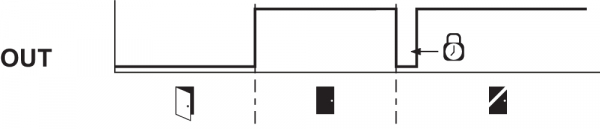
ドアをロック出来ないか故障

 | Lock |  | Unlock | ||
 | Door open |  | Safety guard closed |  | Locking time: 150 ... 250 ms, typically 200 ms |
 | Safety guard not locked or fault |  | Safety guard locked |
Evaluation of the diagnostic output (Version ...-1P2PW)
| Table 1: Diagnostic information of the safety switchgear | ||||||||
|---|---|---|---|---|---|---|---|---|
| System condition | Magnet control IN | LED | Safety outputs Y1, Y2 | Diagnostic output OUT | ||||
| Power to unlock | Power to lock | green | red | yellow | AZM201Z | AZM201B | -1P2PW | |
| Door open | 24 V (0 V) | 0 V (24 V) | On | Off | Off | 0 V | 0 V | 0 V |
| Door closed, actuator not inserted | 24 V | 0 V | On | Off | Off | 0 V | 0 V | 0 V |
| Door closed, actuator inserted, not locked | 24 V | 0 V | On | Off | Flashes | 0 V | 24 V | 24 V |
| Door closed, actuator inserted, interlocking blocked | 0 V | 24 V | On | Off | Flashes | 0 V | 24 V | 0 V |
| Door closed, actuator inserted and locked | 0 V | 24 V | On | Off | On | 24 V | 24 V | 24 V |
| Error warning1) solenoid interlock locked | 0 V | 24 V | On | Flashes 2) | On | 24 V1) | 24 V1) | 0 V |
| Error | 0 V (24 V) | 24 V (0 V) | On | Flashes2)/Off1) | Off | 0 V | 0 V | 0 V |
| Additionally for variant I1/I2: | ||||||||
| Teach-in procedure actuator started | Off | On | Flashes | 0 V | 0 V | 0 V | ||
| Only I2: teach-in procedure actuator (release block) | Flashes | Off | Off | 0 V | 0 V | 0 V | ||
1) after 30 min. disabling due to fault 2) see flash code | ||||||||
| Table 2: Error messages / flash codes red diagnostic LED | |||
|---|---|---|---|
| Flash codes | Designation | Autonomous switch-off after | Error cause |
| 1 flash pulse | Error (warning) at output Y1 | 30 min | Fault in output test or voltage at output Y1, although the output is disabled. |
| 2 flash pulses | Error (warning) at output Y2 | 30 min | Fault in output test or voltage at output Y2, although the output is disabled. |
| 3 flash pulses | Error (warning) cross-wire short | 30 min | Cross-wire short between the output cables or fault at both outputs |
| 4 flash pulses | Error (warning) temperature too high | 30 min | The temperature measurement reveals an internal temperature that is too high |
| 5 flash pulses | Actuator fault | 0 min | Incorrect or defective actuator |
| 6 flash pulses | Error actuator combination | 0 min | An invalid combination of actuators was detected (blocking bolt detection or tamper attempt). |
| Continuous red signal | Internal fault / overvoltage or undervoltage fault | 0 min | Device defective / supply voltage not within specifications |
6.5 直列診断機能SD付き電磁ロック付きインターロック
シリアル診断ケーブル付き電磁ロック付きインターロックには、従来型の診断出力の代わりに、シリアル入出力ケーブルを有しています。直列接続する場合は、これらの入力・出力ケーブルは直列接続により診断データを伝送します。
最大31個の電磁ロック付きインターロックが直列に接続出来ます。シリアル診断ラインの評価には PROFIBUSゲートウェイ SD-I-DP-V0-2 又はユニバーサルゲートウェイ SD-I-U-... を使用します。このシリアル診断用インターフェースはスレーブとして既存のフィールドバスシステムに組み込めます。この様にして、診断信号はPLCで評価出来ます。
SDゲートウェイの接続に関する必要なソフトウェアは、products.schmersal.comからダウンロード出来ます。
応答データと診断データは、直列に接続された個々の電磁ロック付きインターロック用に自動的・継続的にPLCの入力バイトに書き込まれます。電磁ロック付きインターロック用の要求データは、PLCの出力バイトを通じてコンポーネントに伝送されます。SDゲートウェイと電磁ロック付きインターロック間の通信エラーが発生した場合、電磁ロック付きインターロックのスイッチング状態が維持されます。
Error
Errors which no longer guarantee the function of the safety switchgear (internal errors) cause the safety outputs to be disabled within the duration of risk. The fault is reset, when the cause is eliminated and bit 7 of the request byte changes from 1 to 0 or the safety guard is opened. Faults at the safety outputs are only deleted upon the next release, as the fault rectification cannot be detected sooner.
- Automatic, electronic locking takes place if more than one fault is detected at the safety outputs or a cross circuit is detected between Y1 and Y2. This means that normal fault acknowledgement is no longer possible. To reset this type of interlock, the solenoid interlock must be isolated from the supply voltage after elimination of the error causes.
Error warning
A fault that does not immediately endanger the safety function of the safety switchgear (e.g. too high ambient temperature, safety output at external potential, cross-circuit) leads to delayed shutdown. This signal combination, diagnostic output disabled and safety channels still enabled, can be used to stop the production process in a controlled manner.
An error warning is deleted when the cause of error is eliminated.
If the fault warning remains on for 30 minutes, the safety outputs are also switched off (red LED flashes).
診断エラー(警告)
応答バイトにおいてエラー(警告)が発せられた場合、詳細な情報を読み出す事が出来ます。
| Table 3: I/O data and diagnostic data (The described condition is reached, when Bit = 1) | ||||
|---|---|---|---|---|
| Bit n° | Request byte | Response byte | Diagnostic error warning | Diagnostic error |
| Bit 0: | Magnet in, irrespective of power to lock or power to unlock principle | Safety output activated | Error output Y1 | Error output Y1 |
| Bit 1: | --- | Actuator detected | Error output Y2 | Error output Y2 |
| Bit 2: | --- | Actuator detected and locked | Cross-wire short | Cross-wire short |
| Bit 3: | --- | --- | Temperature too high | Temperature too high |
| Bit 4: | --- | Input condition X1 and X2 | --- | Incorrect or defective actuator |
| Bit 5: | --- | Guard door detected | Internal device error | Internal device error |
| Bit 6: | --- | Error warning 1) | Communication error between the field bus Gateway and the safety switchgear | --- |
| Bit 7: | Error reset | Error (enabling path switched off) | Operating voltage too low | --- |
| 1) after 30 min -> fault | ||||
7 セットアップとメンテナンス
The safety function of the safety components must be tested. In the case of correct installation and adequate use, the safety switchgear features maintenance-free functionality. A regular visual inspection and functional test, including the following steps, is recommended:
- Check fixation of the safety switch and the actuator.
- Check max. axial misalignment of actuator and safety switch.
- Fitting and integrity of the cable connections.
- Check the switch enclosure for damages
- Remove particles of dust and soiling.
- 予備のアクチュエータを使うなどのセーフティガードの改ざんを防止し、無効化から保護するために、適切な方策を講じなくてはなりません。
- 破損、故障の場合は交換してください。
8 取り外し・廃棄
8.1 取り外し
セーフティスイッチの取り外しは非通電状態で行わなければなりません。
8.2 廃棄処分
- セーフティスイッチは国家規格や法規に従って、適切な措置により廃棄しなければなりません。
9 Appendix – Special versions
Special version -2965-1
| Connecting cables with coupling (female) IP67, M23, 12 pole - 12 x 0.75 mm² | |
|---|---|
| Cable length | Ordering code |
| 5.0 m | 101208520 |
| 10.0 m | 103007354 |
| 20.0 m | 101214418 |
Special version -2965-2
| Connecting cables with coupling (female) IP67, M23, 8+1 pole - 9 x 0.75 mm² | |
|---|---|
| Cable length | Ordering code |
| 5.0 m | 101209959 |
| 10.0 m | 101209958 |
| 15.0 m | 103001384 |
| Connecting cables with coupling (female) IP67, M12, 8 pole - 8 x 0.25 mm² | |
|---|---|
| Cable length | Ordering code |
| 2.5 m | 103011415 |
| 5.0 m | 103007358 |
| 10.0 m | 103007359 |
Special version -2965-3
| Connecting cables with coupling (female) IP67, M12, 8 pole - 8 x 0.25 mm² | |
|---|---|
| Cable length | Ordering code |
| 2.5 m | 103011415 |
| 5.0 m | 103007358 |
| 10.0 m | 103007359 |
| EU適合宣言書 |  |
| Original | K.A. Schmersal GmbH & Co. KG Möddinghofe 30 42279 Wuppertal Germany Internet: www.schmersal.com |
| 宣言: | ここに、以下に述べるコンポーネントが、その基本設計と構造に於いて、適用可能な欧州指令に適合している事を宣言する。 |
| 製品名 | AZM201 |
| タイプ: | 型式記号参照 |
| 製品内容 | 電磁ロック付きインターロック |
| 関連指令: | 2006/42/EG | 機械指令 |
| 2011/65/EU | RoHS指令 | |
| 2014/53/EU | RED指令 |
| Applied standards: | EN 60947-5-3:2013 ISO 14119:2013 EN 300 330 V2.1.1:2017 EN ISO 13849-1:2015 EN 61508 parts 1-7:2010 |
| 型式検定試験所: | TÜV Rheinland Industrie Service GmbH Am Grauen Stein, 51105 Köln ID番号: 0035 |
| タイプの試験証明書: | 01/205U/5608.00/22 |
| 技術文書の責任者 | Oliver Wacker Möddinghofe 30 42279 Wuppertal |
| 発行場所・日付 | Wuppertal, 2022年9月28日 |
 |
| 正式署名 Philip Schmersal 社長 |
| UK Declaration of Conformity | |
| Company: | K.A. Schmersal GmbH & Co. KG Möddinghofe 30 42279 Wuppertal Germany Internet: www.schmersal.com |
| Declaration: | We hereby, under sole responsibility, certify that the hereafter described components both in their basic design and construction conform to the relevant statutory requirements, regulations and designated standards of the United Kingdom. |
| Name of the component: | AZM201 |
| Type: | See ordering code |
| Description of the component: | Interlocking device with electromagnetic interlock for safety functions |
| Relevant legislation: | Supply of Machinery (Safety) Regulations | 2008 |
| Radio Equipment Regulations | 2017 | |
| The Restriction of the Use of Certain Hazardous Substances in Electrical and Electronic Equipment Regulations | 2012 |
| Designated standards: | EN 60947-5-3:2013 ISO 14119:2013 EN 300 330 V2.1.1:2017 EN ISO 13849-1:2015 EN 61508 parts 1-7:2010 |
| Approved body for Type Examination: | TÜV Rheinland UK Ltd. 1011 Stratford Road Solihull, B90 4BN ID: 2571 |
| Type examination certificate: | 01/205U/5608.00/22 |
| UK-Importer / Person authorised for the compilation of the technical documentation: | Schmersal UK Ltd. Paul Kenney Unit 1, Sparrowhawk Close Enigma Business Park Malvern, Worcestershire, WR14 1GL |
| Place and date of issue: | Wuppertal, September 28, 2022 |
|
| Authorised signature Philip Schmersal Managing Director |
シュメアザー株式会社, 〒222-0033 横浜市港北区新横浜3-9-5, 新横浜第3東昇ビル
データと詳細は完全にチェックされました。画像は元の画像と異なる場合があります。技術的なデータはマニュアルで見られます。技術的に変更されたり、エラーの可能性があります。
Generated on 2024/04/18 3:06