BDF200-SD-NHK-SWS20-LTBU-LTRD
BDF200-SD-NHK-SWS20-LTBU-LTRD
- slender shock-proof thermoplastic enclosure
- to be installed at an ergonomic favourable position
- to be fitted to commercial-off-the-shelf aluminium profiles
- E-STOP with electronic OSSDs
Ordering data
| Product type description |
BDF200-SD-NHK-SWS20-LTBU-LTRD |
| Article number (order number) |
103050608 |
| EAN (European Article Number) |
4030661628417 |
| eCl@ss number, version 12.0 |
27-37-12-16 |
| eCl@ss number, version 11.0 |
27-37-12-16 |
| eCl@ss number, version 9.0 |
27-37-12-16 |
| ETIM number, version 7.0 |
EC000225 |
| ETIM number, version 6.0 |
EC000225 |
| Note (Ordering data) |
Opmerking: zie bestelsleutel |
Approvals - Standards
| Certificates |
cULus |
General data
| Standards |
EN ISO 13849-1 EN ISO 13850 EN IEC 60947-5-1 EN IEC 60947-5-5 EN IEC 61508 |
| Climatic stress |
DIN EN 60068 |
| Housing material |
Kunststof, glasvezelversterkte thermoplast, zelfdovend |
| Reaction time, maximum |
50 ms |
| Duration of risk, maximum |
100 ms |
| Positions used, position 1 |
Noodstopdrukknop, met beschermkraag |
| Positions used, position 2 |
Key selector switch 2 positions |
| Positions used, position 3 |
Verlichte drukknop, blauw |
| Positions used, position 4 |
Verlichte drukknop, rood |
| Gross weight |
280 g |
General data - Features
| Serial diagnostics |
Ja |
| Field box interface |
Nein |
| Indicator lamp |
Neen |
| Safety functions |
Ja |
| Number of fail-safe digital outputs |
2 |
| Safety classification |
| Vorschriften |
EN ISO 13849-1 EN IEC 61508 |
| Performance Level, up to |
e |
| Category |
4 |
| PFH value |
2,89 x 10⁻¹⁰ /h |
| Note (PFH-value) |
tot max. 5.000 schakelcycli/jaar |
| Safety Integrity Level (SIL), suitable for applications in |
3 |
| Mission time |
20 Year(s) |
Mechanical data
| Mechanical life, Emergency-Stop button |
100.000 Operations |
| Mechanical life, Command devices |
1.000.000 Operations |
| Mounting |
Bevestigingsgaten aan de binnenkant |
| Type of the fixing screws |
2x M5 |
Mechanical data - Connection technique
| Terminal (mechanical) |
Inbouwstekker M12, 8-polig, A-codering |
Mechanical data - Dimensions
| Width |
40 mm |
| Height |
69 mm |
| Depth |
233,5 mm |
Ambient conditions
| Degree of protection |
IP65 |
| Ambient temperature |
-25 ... +65 °C |
| Storage and transport temperature |
-25 ... +85 °C |
| Resistance to vibrations |
10 … 150 Hz, Amplitude 0,35 mm / 5 g |
| Restistance to shock |
30 g / 11 ms |
| Protection class |
III |
| Permissible installation altitude above sea level, maximum |
2.000 m |
Ambient conditions - Insulation values
| Rated insulation voltage Ui |
32 VDC |
| Rated impulse withstand voltage Uimp |
0,8 kV |
| Overvoltage category |
III |
| Degree of pollution |
3 |
Electrical data
| Operating voltage |
24 VDC -15 % / +10 % |
| No-load supply current I0, typical |
35 mA |
| Rated operating voltage |
24 VDC |
| Operating current |
600 mA |
| Required rated short-circuit current |
100 A |
| Time to readiness, maximum |
2.000 ms |
| Switching frequency, maximum |
1 Hz |
Electrical data - Safety digital inputs
| Designation, Safety inputs |
X1 en X2 |
| Switching thresholds |
−3 V … 5 V (Low) 15 V … 30 V (High) |
| Current consumption at 24 V |
5 mA |
| Test pulse duration, maximum |
1 ms |
| Test pulse interval, minimum |
100 ms |
| Classification ZVEI CB24I, Sink |
C1 |
| Classification ZVEI CB24I, Source |
C1 C2 C3 |
Electrical data - Safety digital outputs
| Designation, Safety outputs |
Y1 en Y2 |
| Design of control elements |
kortsluitvast, p-schakelend |
| Voltage drop Ud, maximum |
1 V |
| Leakage current Ir, maximum |
0,5 mA |
| Voltage, Utilisation category DC-12 |
24 VDC |
| Current, Utilisation category DC-12 |
0,25 A |
| Voltage, Utilisation category DC-13 |
24 VDC |
| Current, Utilisation category DC-13 |
0,25 A |
| Test pulse interval, typical |
1000 ms |
| Test pulse duration, maximum |
1 ms |
| Classification ZVEI CB24I, Source |
C1 |
| Classification ZVEI CB24I, Sink |
C1 |
Electrical data - Serial diagnostic SD
| Designation, Serial diagnostic SD |
OUT |
| Operation current |
100 mA |
| Design of control elements |
kortsluitvast, p-schakelend |
| Wiring capacitance |
50 nF |
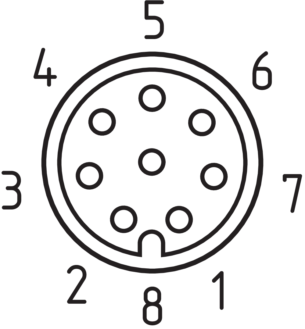
Pin assignment
| PIN 1 |
A1 Toevoerspanning UB |
| PIN 2 |
X1 Veiligheidsingang 1 |
| PIN 3 |
A2 GND |
| PIN 4 |
Y1 Veiligheidsuitgang 1 |
| PIN 5 |
OUT uitgang voor seriële diagnose |
| PIN 6 |
X2 Veiligheidsingang 2 |
| PIN 7 |
Y2 Veiligheidsuitgang 2 |
| PIN 8 |
IN ingang voor seriële diagnose |
Taalfilter
Datasheet
Bedieningshandleiding en conformiteitsverklaring
UL-certificaat
SISTEMA-VDMA-bibliotheek/library
Download de nieuwste versie van Adobe Reader
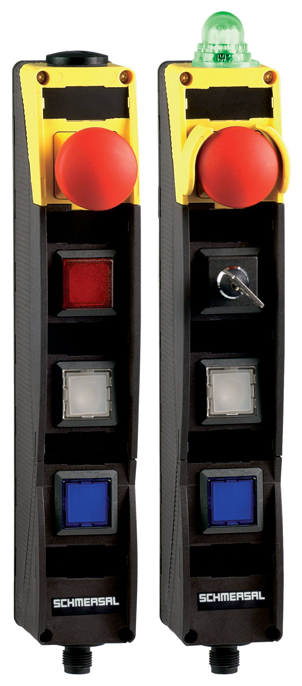
Foto van het product (individuele catalogusfoto)
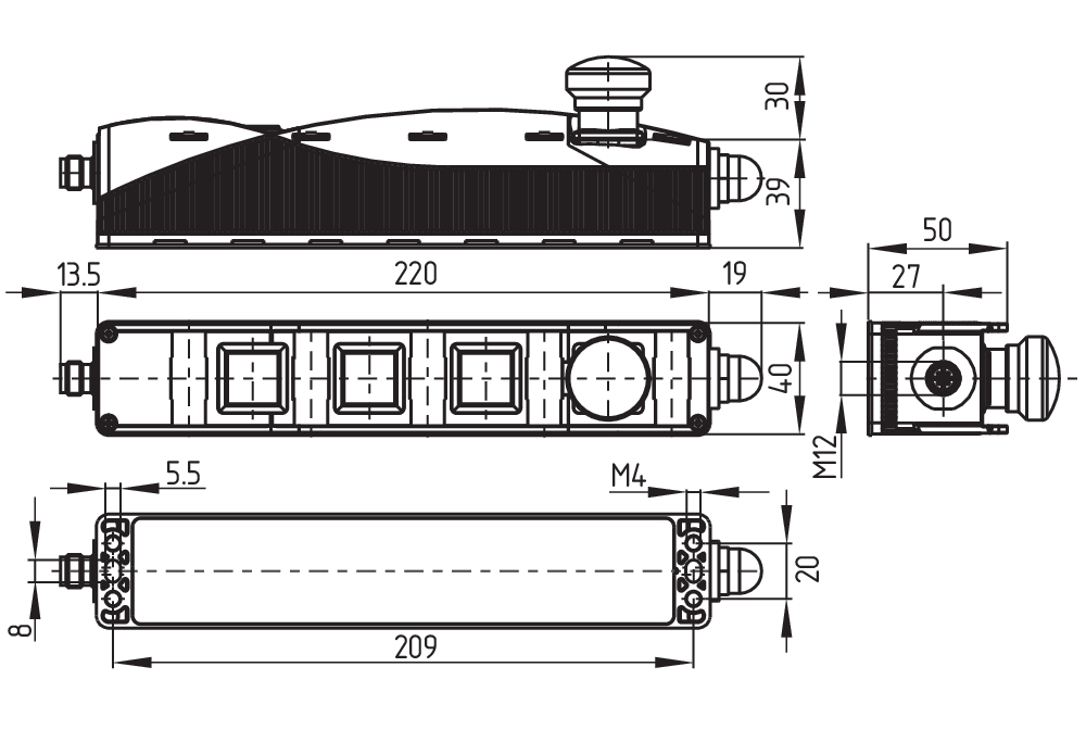
Maatschets basistoestel
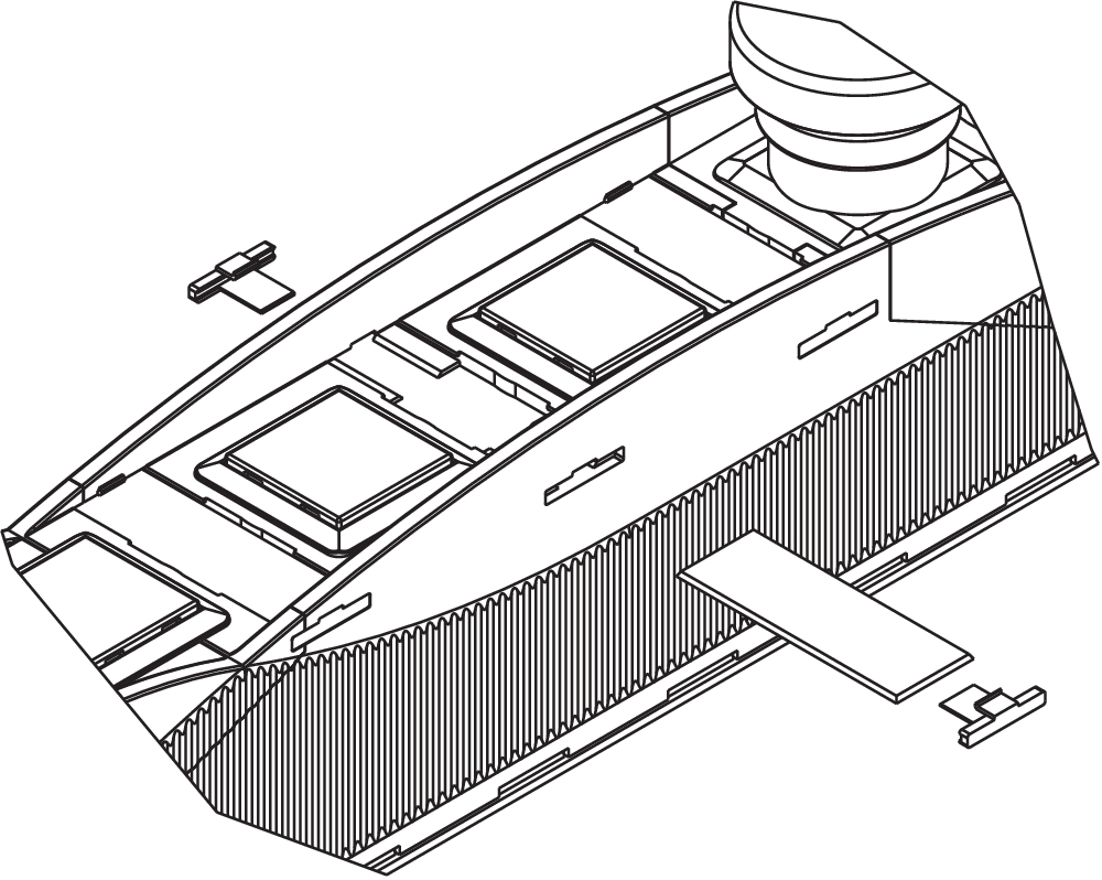
Werkwijze, werkingsprincipe
Clipart


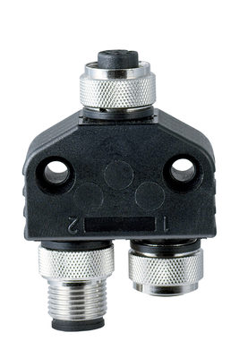
101209414 CSS-Y-A-8P
- Accessories for series-wiring with serial diagnostics
- The connector supplies the safety channels with operating voltage.
103008718 CSS-Y-A-8P-VA
- Accessories for series-wiring with serial diagnostics
- The connector supplies the safety channels with operating voltage.
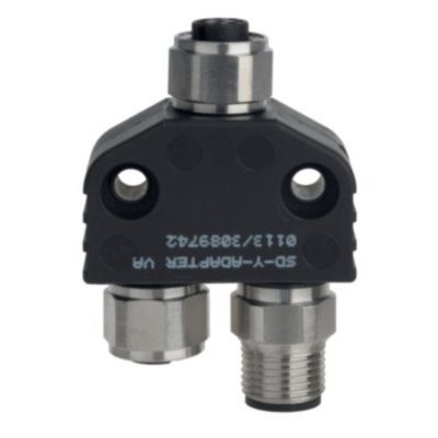
103009361 SD-Y-POWER
- Accessories for series-wiring with serial diagnostics
103009362 SD-Y-POWER VA
- Accessories for series-wiring with serial diagnostics
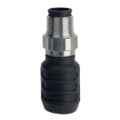
101190026 CSS-T
- Accessories for series-wiring with serial diagnostics
- for Sensors

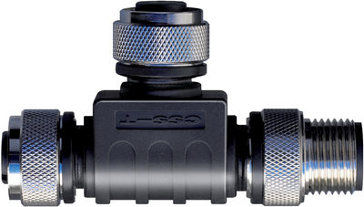
101190025 CSS-T-A
- Accessories for series-wiring with serial diagnostics
- for CSS 34

101209416 CSS-Y-8P
- Accessories for series-wiring with serial diagnostics
103008717 CSS-Y-8P-VA
- Accessories for series-wiring with serial diagnostics
Schmersal India Pvt. Ltd., Plot No - G-7/1, Ranjangaon MIDC, Tal. - Shirur, Dist.- Pune 412 220
De genoemde gegevens en informatie zijn zorgvuldig gecontroleerd. Afbeeldingen kunnen afwijken van het origineel. Verdere technische gegevens zijn te vinden in de handleiding. Technische wijzigingen en fouten voorbehouden.
Gegenereerd op 27-04-2025 11:30
Recent bekeken
BN 120L-10Z 2,0M