SRB219IT-24VAC/DC
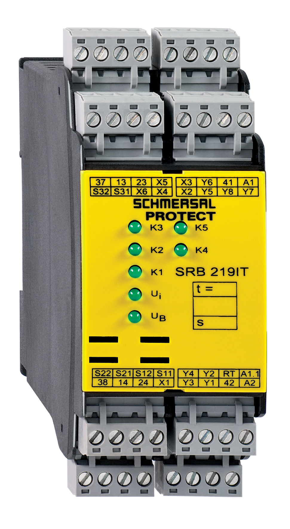
SRB219IT-24VAC/DC
Downloads
- Multifunctional safety relay module for superior diagnostics and visualisation
- Suitable for the signal processing of outputs with contact sensors
- Suitable for the signal processing of outputs with contact sensors
- Suitable for signal processing of outputs connected to potentials (AOPDs), e.g. safety light grids/curtains
- 1 + 8 Signalling outputs
- 2 safety contacts, STOP 0;
1 safety contact, STOP 1 (adjustable 1 … 30 s)
Ordering data
| Note (Delivery capacity) |
Niet meer verkrijgbaar! |
| Replacement article number |
101159512 |
| Product type description |
SRB219IT-24VAC/DC |
| Article number (order number) |
101158208 |
| EAN (European Article Number) |
4250116201570 |
| eCl@ss number, version 12.0 |
27-37-18-19 |
| eCl@ss number, version 11.0 |
27-37-18-19 |
| eCl@ss number, version 9.0 |
27-37-18-19 |
| ETIM number, version 7.0 |
EC001449 |
| ETIM number, version 6.0 |
EC001449 |
Approvals - Standards
| Certificates |
cULus |
General data
| Standards |
EN IEC 62061 EN ISO 13849-1 EN IEC 60947-5-1 EN IEC 60947-5-3 EN IEC 60947-5-5 EN IEC 61508 EN IEC 60204-1 EN IEC 60947-1 |
| Climatic stress |
EN 60068-2-78 |
| Housing material |
Kunststof, glasvezelversterkte thermoplast, geventileerd |
| Gross weight |
360 g |
General data - Features
| Electronic Fuse |
Ja |
| Wire breakage detection |
Ja |
| Cross-circuit detection |
Ja |
| Removable Terminals |
Ja |
| Start input |
Ja |
| Feedback circuit |
Ja |
| Automatic reset function |
Ja |
| Reset edge detection |
Ja |
| Earth connection detection |
Ja |
| Integral system diagnostics, status |
Ja |
| Number of auxiliary contacts |
1 |
| Number of LEDs |
7 |
| Number of normally closed (NC) |
2 |
| Number of undelayed semi-conductor outputs with signaling function |
7 |
| Number of delayed semi-conductor outputs with signaling function. |
1 |
| Number of safety contacts |
3 |
| Number of signalling outputs |
8 |
| Safety classification |
| Vorschriften |
EN IEC 60947-5-1 EN IEC 61508 |
| Stop-Category |
0 1 |
| Safety classification - Relay outputs |
| Performance Level, stop 0, up to |
e |
| Performance Level, stop 1, up to |
d |
| Category, Stop 0 |
4 |
| Category, Stop 1 |
3 |
| Diagnostic Coverage (DC) Level, Stop 0 |
≥ 99 % |
| Diagnostic Coverage (DC) Level, Stop 1 |
> 60 |
| PFH value, Stop 0 |
2,00 x 10⁻⁸ /h |
| PFH value, Stop 1 |
2,00 x 10⁻⁷ /h |
| Safety Integrity Level (SIL), Stop 0, suitable for applications in |
3 |
| Safety Integrity Level (SIL), Stop 1, suitable for applications in |
2 |
| Mission time |
20 Year(s) |
| Common Cause Failure (CCF), minimum |
65 |
Mechanical data
| Mechanical life, minimum |
10.000.000 Operations |
| Mounting |
Snelbevestiging voor DIN-rail volgens DIN EN 60715 |
Mechanical data - Connection technique
| Terminal designations |
IEC/EN 60947-1 |
| Termination |
stijf of flexibel Schraubanschluss M20 x 1.5 |
| Cable section, minimum |
0,25 mm² |
| Cable section, maximum |
2,5 mm² |
| Tightening torque of Clips |
0,6 Nm |
Mechanical data - Dimensions
| Width |
45 mm |
| Height |
100 mm |
| Depth |
121 mm |
Ambient conditions
| Degree of protection of the enclosure |
IP40 |
| Degree of protection of the mounting space |
IP54 |
| Degree of protection of clips or terminals |
IP20 |
| Ambient temperature |
-25 ... +45 °C |
| Storage and transport temperature |
-40 ... +85 °C |
| Resistance to vibrations |
10...55 Hz, Amplitude 0,35 mm, ± 15 % |
| Restistance to shock |
30 g / 11 ms |
Ambient conditions - Insulation values
| Rated impulse withstand voltage Uimp |
4 kV |
| Overvoltage category |
III |
| Degree of pollution |
2 |
Electrical data
| Frequency range |
50 Hz 60 Hz |
| Operating voltage |
24 VAC -15 % / +10 % |
| Ripple voltage |
10 % |
| Rated operating voltage |
24 VAC |
| Rated operating voltage |
24 VDC |
| Operating current |
200 mA |
| Rated AC voltage for controls, 50 Hz, minimum |
20,4 VAC |
| Rated control voltage at AC 50 Hz, maximum |
26,4 VAC |
| Rated AC voltage for controls, 60 Hz, minimum |
20,4 VAC |
| Rated control voltage at AC 60 Hz, maximum |
26,4 VAC |
| Rated AC voltage for controls at DC minimum |
20,4 VDC |
| Rated control voltage at DC, maximum |
28,8 VDC |
| Electrical power consumption |
4,4 W |
| Electrical power consumption |
5,2 VA |
| Contact resistance, maximum |
0,1 Ω |
| Note (Contact resistance) |
In nieuwe toestand |
| Drop-out delay in case of "emergency stop", maximum |
15 ms |
| Pull-in delay at automatic start, maximum, typically |
60 ms |
| Pull-in delay at RESET, typically |
200 ms |
| Material of the contacts, electrical |
AgSn0. zelfreinigend, gedwongen uitgevoerd |
Electrical data - Digital inputs
| Conduction resistance, maximum |
40 Ω |
Electrical data - Electromagnetic compatibility (EMC)
| EMC rating |
EMC-Richtlijn |
Status indication
| Indicated operating states |
Positie relais K2 Positie relais K1 Interne bedrijfsspanning Ui Positie relais K3 Positie relais K5 |
Other data
| Note (applications) |
Veiligheidssensor Beschermvoorziening Noodstopknop Noodstop-trekkoordschakelaars Veiligheidslichtgordijn |
Note
| Note (General) |
Inductieve verbruikers (externe relais, enz.) zijn via een aangepaste bedrading te ontstoren. |
Wiring example
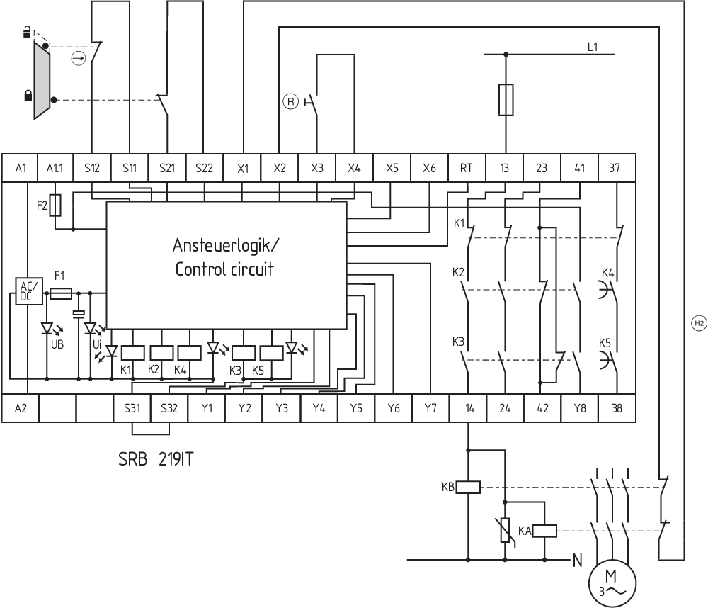
| Note (Wiring diagram) |
Het schakelvoorbeeld is afgebeeld bij gesloten beschermvoorzieningen en in spanningsloze toestand. De ISD-tabellen (geïntegreerde systeemdiagnose) voor analyse van de foutmeldingen en hun oorzaken worden in bijlage vermeld. De sturing herkent kabelbreuken en aardlekken in het bewakingscircuit. Vermogensvlak: voldoet voor 2-kanalige aansturing,als contactversterking en/of contactvermenigvuldiging via externe relais met gedwongen uitgevoerde contacten. Potentiaal belaste uitgangen van veiligheidslichtgordijnen/-lichtschermen (p-schakelend) op S12/S22 aansluiten. De toestellen moeten dezelfde referentiepotentiaal hebben. Tijdsvertraging: Het tijdsvertraagde vrijgavecontact 37/38 kan met een afvalvertraging van 1 tot 30 seconden ingesteld worden (zie instelinstructies). De gewenste tijdsvertraging wordt met behulp van een potentiometer aan de voorkant van de behuizing ingesteld (afdekplaatje wegnemen). Bij een 2-kanalige aansturing met dwarssluitbewaking, het verbreekcontact aansluiten op S11/S12 en S31/S32 en S21/S22 overbruggen Startfunctie / Resetknop: De functie "afvallende flank" wordt geprogrammeerd met behulp van de "AF" schakelaar onder het deksel van de behuizing (positie schakelaar = 1). De automatische start wordt geprogrammeerd door het overbruggen van de klemmen X3/ Ingangsniveau: Het voorbeeld toont een 2-kanalige aansturing van een veiligheidsdeurbewaking met twee positieschakelaars, waarvan een met gedwongen verbreking, externe resetknop (R) en terugkoppeling (H2). (voorbeeld zonder dwarssluitingsbewaking) Bij 1-kanalige aansturing, het verbreekcontact op S11/S12 aansluiten en S21/S22 + S31/S32 overbruggen Voortijdige uitschakeling van de tijdvertraging: via de ingang RT kan de afvalvertraging voortijdig beëindigd worden. Via ingang RT kan het tijdvertraagde vrijgavecontact 37/38 voor het verstrijken van de ingestelde tijd "uitgeschakeld" worden. F1 = hybride-smeltveiligheid F2 = smeltveiligheid signaaluitgangen |
Taalfilter
Datasheet
Bedieningshandleiding en conformiteitsverklaring
UL-certificaat
Schakelvoorbeeld (elektrische kabels)
Krachtveld diagram
Download de nieuwste versie van Adobe Reader
Foto van het product (individuele catalogusfoto)
Schakelvoorbeeld
Symbool (technische standaard)

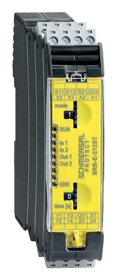
103007222 SRB-E-212ST
- Plug-in screw terminals with coding
- STOP 0 / 1 Function
- 1 oder 2-channel control
- 2 safety contacts STOP 0
- 1 Safety output STOP 1
- Drop-out delay 0 … 30
Schmersal India Pvt. Ltd., Plot No - G-7/1, Ranjangaon MIDC, Tal. - Shirur, Dist.- Pune 412 220
De genoemde gegevens en informatie zijn zorgvuldig gecontroleerd. Afbeeldingen kunnen afwijken van het origineel. Verdere technische gegevens zijn te vinden in de handleiding. Technische wijzigingen en fouten voorbehouden.
Gegenereerd op 19-04-2025 10:18