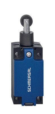
BN 65-10Z/V

BN 65-10Z/V
Downloads
- With pre-wired cable
- Actuation from front
- with bias magnet
- Non-contact principle
- Long life
- Actuating surface and direction of actuation marked by switch symbol
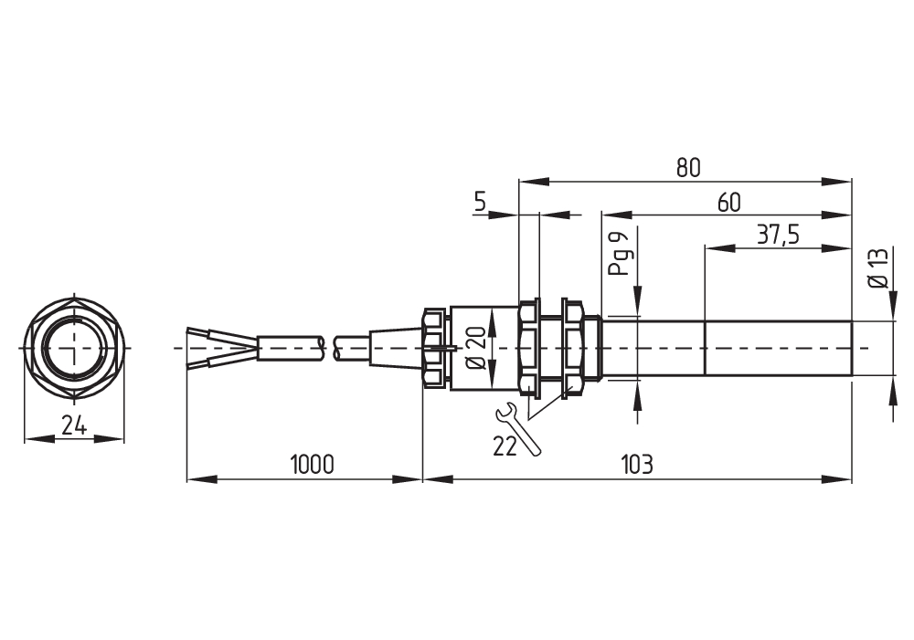
- Construction form Ø 13 mm
- Thermoplastic enclosure
- Actuating distance up to 60 mm depending on actuating magnet and version
- with central mounting
Ordering data
| Product type description |
BN 65-10Z/V |
| Article number (order number) |
101055824 |
| EAN (European Article Number) |
4030661009797 |
| eCl@ss number, version 12.0 |
27-27-43-02 |
| eCl@ss number, version 11.0 |
27-27-01-05 |
| eCl@ss number, version 9.0 |
27-27-01-05 |
| ETIM number, version 7.0 |
EC002544 |
| ETIM number, version 6.0 |
EC002544 |
Approvals - Standards
| Certificates |
cULus |
General data
| Working principle |
Magnetisk drev |
| Housing construction form |
Sylinder, glatt |
| Housing material |
Plast, glassfiber forsterket termoplast |
| Gross weight |
74 g |
General data - Features
| Suitable for elevators |
Ja |
| bias magnet |
Ja |
| Number of normally open (NO) |
1 |
Mechanical data
| Actuating panels |
frontside |
| Actuating element |
Magnet |
| Mechanical life, minimum |
1 000 000 000 Operations |
| Actuating speed, maximum |
18 m/s |
| Mounting |
sentral med gjenget flens |
| Tightening torque of nuts, maximum |
3 Nm |
Mechanical data - Switching distances
| Switching distance Sn |
5 mm … 55 mm BP 10S = 5 mm 2 x BP 10S = 10 mm BP 15S = 6 mm BP 34S = 20 mm BP 20S = 15 mm BP 31S = 15 mm BP 11S = 5 mm 2 x BP 11S = 15 mm BP 12S = 10 mm 2 x BP 12S = 25 mm BP 21S = 30 mm 2 x BP 21S = 20 ... 55 mm BP 22S = 25 mm 2 x BP 22S = 15 ... 55 mm BE 20 S = 6 mm |
| Note (Switching distance Sn) |
Aktueringsavstand opp til 55 mm avhengig av aktuerende magnet og versjon Angivelse av koblingsavstandene gjelder ved betjening av enkeltmonterte apparater uten ferromagnetisk påvirkning. Forandring av avstandene, positiv eller negativ, er mulig gjennom ferrmagnetisk påvirkning. Ved plassering av flere magnetaktuatorer må man ta hensyn til den gjensidige påvirkningen. |
| Note (switching distance) |
All switching distances in accordance EN IEC 60947-5-2 |
| Repeat accuracy R |
0,3 mm |
Mechanical data - Connection technique
| Length of cable |
1 m |
| Termination |
Kabel |
| Wire cross-section |
0,75 mm2 |
| Wire cross-section |
18 AWG |
| Material of the Cable mantle |
H03VV-F |
Mechanical data - Dimensions
| Diameter of sensor |
13 mm |
| width across flats |
22 BK |
| Length of sensor |
103 mm |
Ambient conditions
| Degree of protection |
IP67 |
| Ambient temperature |
-25 ... +75 °C |
| Resistance to vibrations |
10 … 55 Hz, Amplitude 1 mm |
| Restistance to shock |
30 g, på sinusbølge-oscillasjon |
| Resistant to vibration |
30 g, på sinusbølge-oscillasjon |
Electrical data
| Switching voltage, maximum |
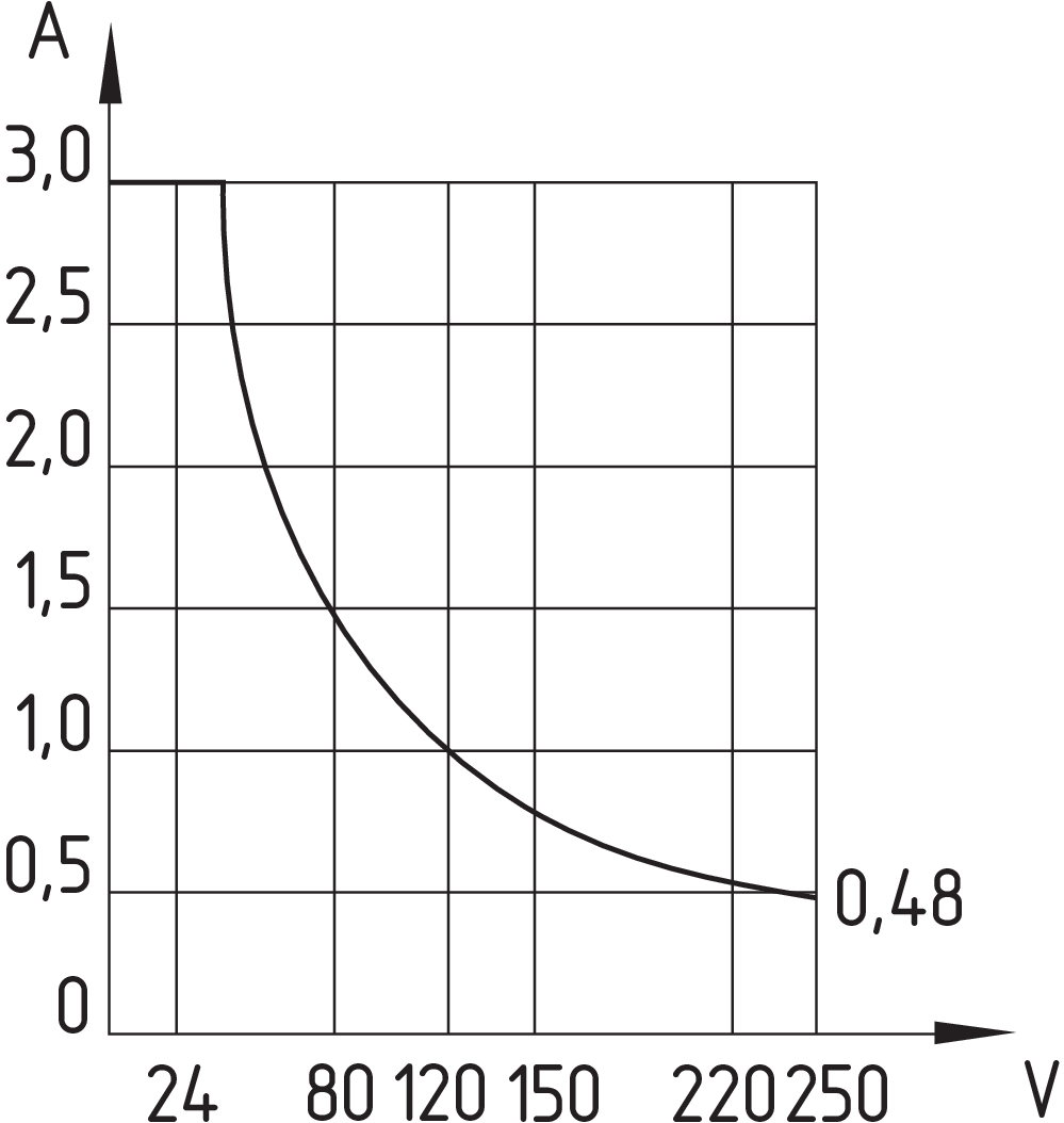
250 VAC |
| Switching current, maximum |
3 A |
| Switching capacity, maximum |
120 W |
| Switching capacity, maximum |
120 VA |
| Switching element |
Normalt åpen kontakt (NO) |
| Bounce duration, minimum |
0,3 ms |
| Bounce duration, maximum |
0,6 ms |
| Switching frequency, maximum |
300 Hz |
| Maximale Schalthäufigkeit |
1 080 000 /h |
Electrical data - Digital Output
| Design of control elements |
Reedkontakter |
Scope of delivery
| Scope of delivery |
Actuator must be ordered separately. |
Accessory
| Recommendation (actuator) |
BP 10 S 2x BP 10 S BP 15 S BP 34 S BP 20 S BP 31 S BP 11 S 2x BP 11 S BP 12 S 2x BP 12S BP 21 S 2x BP 21 S BP 22 S 2x BP 22 S BE 20 S |
| Recommendation (actuator, lift switchgear) |
BP 10 2 x BP 10 BP 15 BP 34 |
Note
| Note (General) |
Bryteren skal monteres på jern med et ikke-magnetisk lag på minst 20 mm. |
Språk filter
Datablad
EU-samsvarserkklæring
UL sertifikat
Info
Last ned den nyeste versjonen av Adobe Reader
Produktbilde (enkelt katalogbilde)
Dimensjonsriktig tegning grunnenhet
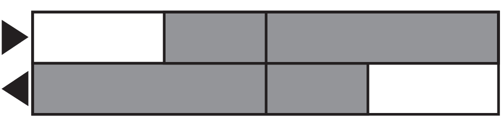
Brytervandringsdiagram
Diagram

Karakteristikk-kurve
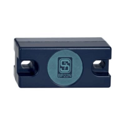
101057432 BP 22 N(S)
- -metal housing
- S-pole marked red
- N-pole marked green
- Suitable for mounting on ferrous material
- Can be used as N or S magnet
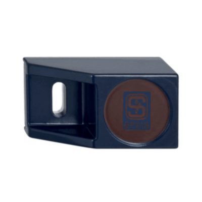
101057534 BP 21 S
- -metal housing
- S-pole marked red
- Suitable for mounting on ferrous material
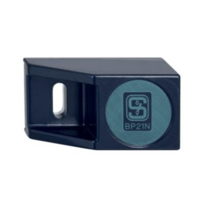
101057536 BP 21 N
- -metal housing
- N-pole marked green
- Suitable for mounting on ferrous material
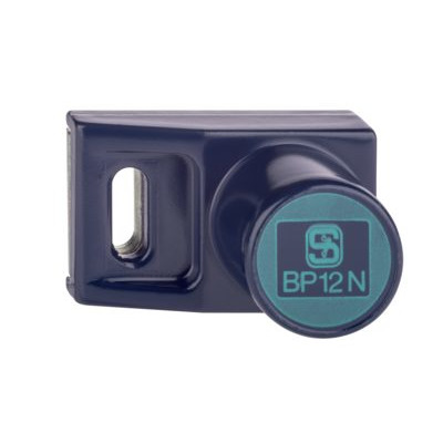
101059917 BP 12 N
- -metal housing
- N-pole marked green
- Suitable for mounting on ferrous material
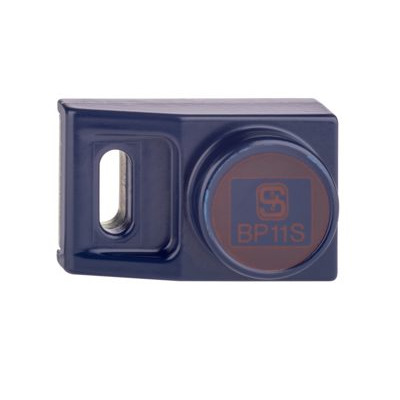
101057533 BP 11 S
- -metal housing
- S-pole marked red
- Suitable for mounting on ferrous material

101059923 BP 11 N
- -metal housing
- N-pole marked green
- Suitable for mounting on ferrous material
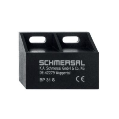
101057521 BP 31 S
- thermoplastic enclosure
- S-pole marked red
- Suitable for mounting on ferrous material with a distance of 20 mm
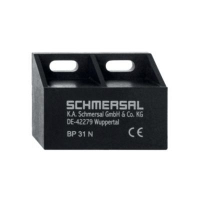
101057520 BP 31 N
- thermoplastic enclosure
- N-pole marked green
- Suitable for mounting on ferrous material with a distance of 20 mm

101057530 BP 31
- thermoplastic enclosure
- S-pole marked red
- N-pole marked green
- Suitable for mounting on ferrous material with a distance of 20 mm

101057541 BP 20 S
- -metal housing
- S-pole marked red
- Suitable for mounting on ferrous material with a distance of 20 mm
101057538 BP 20 N
- -metal housing
- N-pole marked green
- Suitable for mounting on ferrous material with a distance of 20 mm
101057549 BP 20
- -metal housing
- S-pole marked red
- N-pole marked green
- Suitable for mounting on ferrous material with a distance of 20 mm
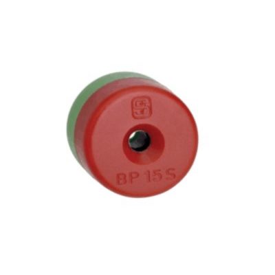
101060163 BP 15
- thermoplastic enclosure
- N-pole marked green
- S-pole marked red
- Suitable for mounting on ferrous material with a distance of 18 mm
101057531 BP 10
- Unenclosed
- Colour coding of poles by lables
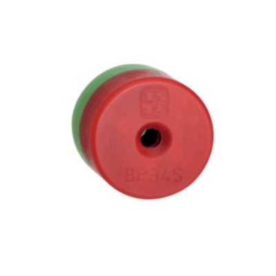
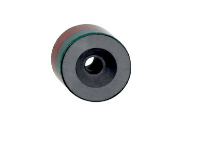
101057553 BP 34
- thermoplastic enclosure
- S-pole marked red
- N-pole marked green
- Suitable for mounting on ferrous material with a distance of 25 mm
Schmersal India Pvt. Ltd., Plot No - G-7/1, Ranjangaon MIDC, Tal. - Shirur, Dist.- Pune 412 220
Data og verdier er kontrollert omhyggelig. Bilder kan avvike fra originalen. Ytterligere tekniske data finner du i manualen. Tekniske modifiseringer og feil kan forkomme.
Generert til 10.04.2025, 03:20
Nylig sett
PS315-T12-R300