CSS 8-180-2P+D-E-L
CSS 8-180-2P+D-E-L
| Oznaczenie typu produktu: CSS 8-180-(1)-(2)-(3) |
| (1) | |
| 2P | 2 wyjścia bezpieczeństwa PNP odporne na zwarcie |
| 2P+D | 2 wyjścia bezpieczeństwa PNP odporne na zwarcie i wyjście diagnostyczne |
| (2) | |
| E | Czujnik pojedyńczy, lub ostatni w łańcuchu |
| Y | Łączenie szeregowe |
| M | połączenie wielofunkcyjne |
| (3) | |
| L | kabel |
| LST | Przewód z konektorem |
| ST | konektor |
- Pre-wired cable 5-pole
- Comfortable diagnostics through sensor LED and electronic signalling output
- Thermoplastic enclosure
- Electronic contact-free, coded system
- Misaligned actuation possible
- High repeat accuracy of the switching points
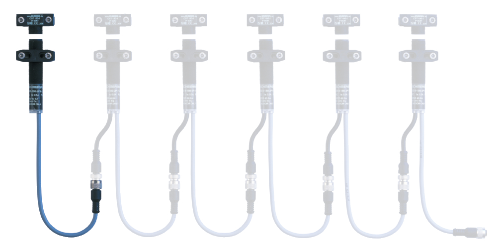
- Max. length of the sensor chain 200 m
- Early warning when operating near the limit of the sensor's hysteris range
- Self-monitoring series-wiring of 16 sensors
- 2 short-circuit proof PNP safety outputs
Ordering data
| Product type description |
CSS 8-180-2P+D-E-L |
| Article number (order number) |
101169552 |
| EAN (European Article Number) |
4030661295954 |
| eCl@ss number, version 12.0 |
27-27-46-01 |
| eCl@ss number, version 11.0 |
27-27-24-03 |
| eCl@ss number, version 9.0 |
27-27-24-03 |
| ETIM number, version 7.0 |
EC001829 |
| ETIM number, version 6.0 |
EC001829 |
Approvals - Standards
| Certificates |
TÜV cULus UKCA |
General data
| Standards |
EN IEC 60947-5-3 EN IEC 61508 |
| Working principle |
indukcyjne |
| Housing construction form |
walec, gwint |
| Installation conditions (mechanical) |
nie wpuszczany |
| Sensor topology |
Czujnik pojedyńczy, lub ostatni w łańcuchu |
| Housing material |
Tworzywo, Tworzywo termoplastyczne wzmocnione włóknem szklanym |
| Active area |
Tworzywo, Tworzywo termoplastyczne wzmocnione włóknem szklanym |
| Material of the nuts |
Tworzywo, Tworzywo termoplastyczne wzmocnione włóknem szklanym |
| Reaction time, maximum |
30 ms |
| Duration of risk, maximum |
30 ms |
| Gross weight |
150 g |
General data - Features
| Short circuit detection |
Tak |
| Cross-circuit detection |
Tak |
| Safety functions |
Tak |
| Integral system diagnostics, status |
Tak |
| Number of semi-conductor outputs with signaling function |
1 |
| Number of fail-safe digital outputs |
2 |
| Number of series-wiring of sensors |
16 |
| Safety classification |
| Vorschriften |
EN ISO 13849-1 EN IEC 60947-5-3 EN IEC 61508 |
| Performance Level, up to |
e |
| Category |
4 |
| PFH value |
2,50 x 10⁻⁹ /h |
| Safety Integrity Level (SIL), suitable for applications in |
3 |
| Mission time |
20 Year(s) |
Mechanical data
| Tightening torque of nuts, maximum |
3 Nm |
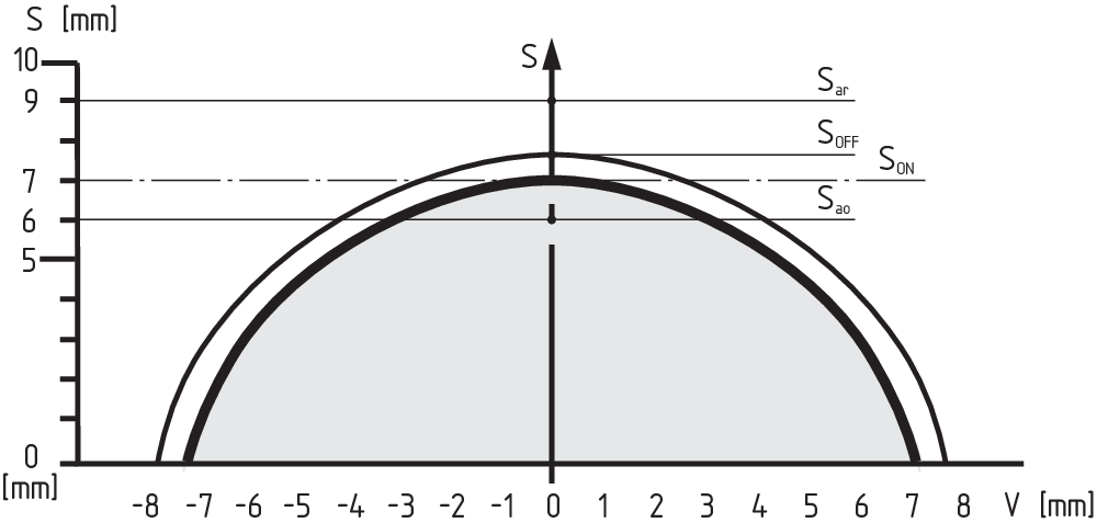
Mechanical data - Switching distances
| Switch distance, typical |
8 mm |
| Assured switching distance "ON" Sao |
7 mm |
| Assured switching distance "OFF" Sar |
10 mm |
| Note (switching distance) |
All switching distances in accordance EN IEC 60947-5-3 |
| Hysteresis (Switching distance), maximum |
0,7 mm |
| Repeat accuracy R |
0,2 mm |
Mechanical data - Connection technique
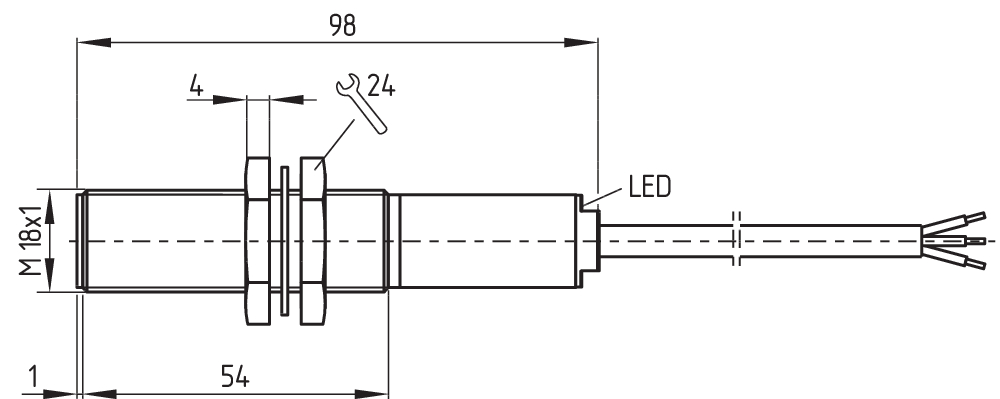
| Length of cable |
1 m |
| Termination |
Kabel |
| Terminal connector, Output |
5-pol. |
| Wire cross-section |
0,35 mm2 |
| Wire cross-section |
22 AWG |
Mechanical data - Dimensions
| ISO thread of the sensor |
M18 |
| width across flats |
24 BK |
| Length of sensor |
92 mm |
Ambient conditions
| Degree of protection |
IP65 IP67 |
| Ambient temperature |
-25 ... +60 °C |
| Storage and transport temperature |
-25 ... +85 °C |
| Resistance to vibrations |
10 … 55 Hz, amplituda 1 mm |
| Restistance to shock |
30 g / 11 ms |
| Protection class |
II |
Ambient conditions - Insulation values
| Rated insulation voltage Ui |
32 VDC |
| Rated impulse withstand voltage Uimp |
0,8 kV |
| Overvoltage category |
III |
| Degree of pollution |
3 |
Electrical data
| Operating voltage |
24 VDC -15 % / +10 % |
| No-load supply current I0, typical |
50 mA |
| Rated operating voltage |
24 VDC |
| Operating current |
1 000 mA |
| Switching frequency, approx. |
3 Hz |
| Utilisation category DC-12 |
24 VDC / 0,05 A |
Electrical data - Safety digital outputs
| Rated operating current (safety outputs) |
500 mA |
| Output current, (fail-safe output), maximum |
0,5 A |
| Design of control elements |
p-type |
| Voltage drop Ud, maximum |
0,5 V |
| Leakage current Ir, maximum |
0,5 mA |
| Voltage, Utilisation category DC-12 |
24 VDC |
| Current, Utilisation category DC-12 |
0,5 A |
| Voltage, Utilisation category DC-13 |
24 VDC |
| Current, Utilisation category DC-13 |
0,5 A |
Electrical data - Diagnostic outputs
| Rated operating voltage |
24 VDC |
| Design of control elements |
typ p |
| Voltage drop Ud, maximum |
4 V |
| Voltage, Utilisation category DC-12 |
24 VDC |
| Current, Utilisation category DC-12 |
0,05 A |
| Voltage, Utilisation category DC-13 |
24 VDC |
| Current, Utilisation category DC-13 |
0,05 A |
Status indication
| Note (LED switching conditions display) |
Wielobarwna dioda LED: zielona, czerwona, żółta |
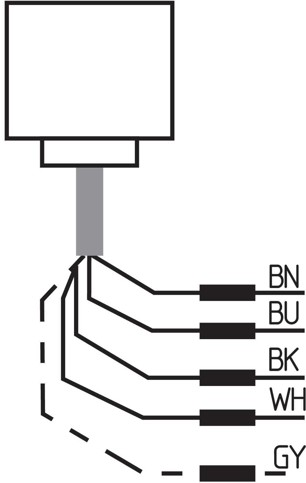
Pin assignment
| PIN 1 |
A1 Ue Brązowe |
| PIN 2 |
Y2 wyjście bezpieczeństwa 2: biały |
| PIN 3 |
A2 GND Niebieskie |
| PIN 4 |
Y1 Wyjście bezpieczne 1 Czarne |
| PIN 5 |
Wyjście sygnalizacyjne: szary |
Scope of delivery
| Scope of delivery |
Actuator must be ordered separately. |
| Scope of delivery of mounting material |
2x Nakrętki M18 x 1 |
Accessory
| Recommendation (actuator) |
CST 180-1 CST 180-2 |
| Recommended safety switchgear |
PROTECT PSC1 SRB-E-301ST SRB-E-201LC |
Note
| Note (General) |
Wymagania względem modułu bezpieczeństwa: 2-kanałowe wejście bezpieczne, odpowiednie dla czujników PNP z funkcją NO. Moduł bezpieczeństwa musi tolerować wewnętrzne testy czujników z cyklicznym wyłączaniem ich wyjść na maks. 0,25 ms. Moduł bezpieczeństwa nie musi dysponować funkcją detekcji zwarcia międzykanałowego. |
Filtr językowy
Karta katalogowa
Instrukcja obsługi i deklaracja zgodności
Certyfikat TÜV
Certyfikat UL
Certyfikat UKCA
Przykład połączeń (okablowanie elektryczne)
Broszura
Biblioteka/Library SISTEMA-VDMA
pobierz najnowszą wersję Adobe Reader
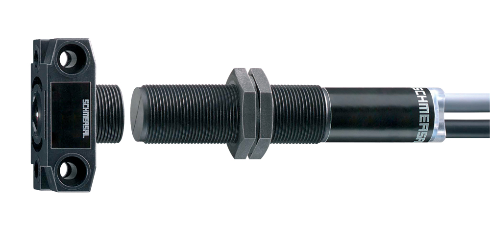
Zdjęcie produktu (pojedyncze zdjęcie katalogowe)
Rysunek wymiarowy Urządzenie podstawowe
Diagram
Krzywa charakterystyczna
Przykład okablowania
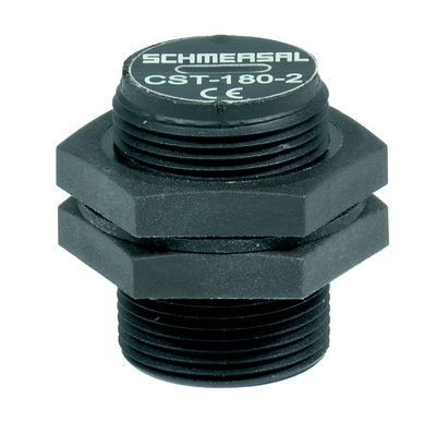
101179574 CST 180-2 KPL.
- Front and lateral actuation of the sensor possible
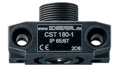
101177198 CST 180-1 KPL
- Front and lateral actuation of the sensor possible
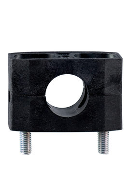
101068879 ACC-IFL-MOCL-H18
- For a smooth fitting of the proximity switches with cylindric shape Ø 18 mm or thread M18
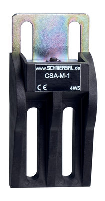
101173457 CSA-M-1 KPL. (CSS 8-180)
- Magnetic snap lock
- For play-free interlocking of light guards

103009970 SRB-E-201LC
- Plug-in screw terminals with coding
- STOP 0 Function
- 1 oder 2-channel control
- Start button / Auto-start
- 2 Safety outputs 2 A
- 1 Signalling output

103009973 SRB-E-204ST
- Plug-in screw terminals with coding
- STOP 0 Function
- Monitoring of 4 sensors
- Start button / Auto-start
- 2 Safety outputs
- 4 Signalling outputs

103007672 SRB-E-301ST
- Plug-in screw terminals with coding
- STOP 0 Function
- 1 oder 2-channel control
- Start button / Auto-start
- 1 Auxiliary contact
- 3 safety contacts
| Deklaracja zgodności UE |  |
| Oryginał | K.A. Schmersal GmbH & Co. KG Möddinghofe 30 42279 Wuppertal Niemcy Internet: www.schmersal.com |
| Wyjaśnienie: | Niniejszym oświadczamy, że niżej wymienione elementy konstrukcyjne spełniają wymagania podanych niżej Europejskich Dyrektyw w zakresie koncepcji i konstrukcji. |
| Oznaczenie elementu konstrukcyjnego: | CSS 8-180 |
| Typ: | patrz klucz zamówieniowy |
| Opis elementu konstrukcyjnego: | Bezdotykowy czujnik bezpieczństwa |
| Odnośne dyrektywy: | Dyrektywa maszynowa | 2006/42/EG |
| Dyrektywa o kompatybilności elektromagnetycznej | 2014/30/EU | |
| Dyrektywa RoHS | 2011/65/EU |
| Zastosowane normy: | EN 60947-5-3:2013 EN ISO 14119:2013 EN ISO 13849-1:2015 EN 61508 część 1-7:2010 |
| Jednostka notyfikowana do badania typu: | TÜV Rheinland Industrie Service GmbH Am Grauen Stein, 51105 Köln Nr ident.: 0035 |
| Certyfikat badania typu WE: | 01/205/5874.00/21 |
| Osoba upoważniona do sporządzenia dokumentacji technicznej: | Oliver Wacker Möddinghofe 30 42279 Wuppertal |
| Miejscowość i data wystawienia: | Wuppertal, 29 listopada 2021 |
 |
| Prawnie wiążący podpis Philip Schmersal Dyrektor |
| UK Declaration of Conformity | |
| Company: | K.A. Schmersal GmbH & Co. KG Möddinghofe 30 42279 Wuppertal Germany Internet: www.schmersal.com |
| Declaration: | We hereby, under sole responsibility, certify that the hereafter described components both in their basic design and construction conform to the relevant statutory requirements, regulations and designated standards of the United Kingdom. |
| Name of the component: | CSS 8-180 |
| Type: | See ordering code |
| Description of the component: | Non-contact safety sensor |
| Relevant legislation: | Supply of Machinery (Safety) Regulations | 2008 |
| Electromagnetic Compatibility Regulations | 2016 | |
| The Restriction of the Use of Certain Hazardous Substances in Electrical and Electronic Equipment Regulations | 2012 |
| Designated standards: | EN 60947-5-3:2013 EN ISO 14119:2013 EN ISO 13849-1:2015 EN 61508 parts 1-7:2010 |
| Approved body for Type Examination: | TÜV Rheinland UK Ltd. 1011 Stratford Road Solihull, B90 4BN ID: 2571 |
| Type examination certificate: | 01/205U/5874.00/23 |
| UK-Importer / Person authorised for the compilation of the technical documentation: | Schmersal UK Ltd. Paul Kenney Unit 1, Sparrowhawk Close Enigma Business Park Malvern, Worcestershire, WR14 1GL |
| Place and date of issue: | Wuppertal, February 6, 2023 |
|
| Authorised signature Philip Schmersal Managing Director |
Schmersal India Pvt. Ltd., Plot No - G-7/1, Ranjangaon MIDC, Tal. - Shirur, Dist.- Pune 412 220
Dane zostały starannie sprawdzone. Zdjęcia mogą odbiegać od rzeczywistości. Dalsze dane techniczne znajdują się w instrukcji obsługi. Możliwe są zmiany i błędy techniczne.
Wygenerowano dnia 22.04.2025, 15:26