AZ 16-02ZVRK-M16-2254
AZ 16-02ZVRK-M16-2254
| Oznaczenie typu produktu: AZ 16-(1)ZV(2)K-(3)-(4)-(5) |
| (1) | |
| bez | 1 zestyk NO / 1 zestyk NC |
| 02 | 2 zestyki NC |
| 03 | 3 zestyki NC |
| 12 | 1 zestyk NO / 2 zestyki NC |
| (2) | |
| bez | Siła wypychająca |
| R | Siła zatrzasku 30 N |
| (3) | |
| G24 | z diodą LED (dostępne tylko dla wersji z jednym zestykiem NO i jednym zestykiem NC.) |
| (4) | |
| M16 | Przepust kablowy M16 |
| M20 | Przepust kablowy M20 |
| ST | Konektor M12. 4-polowy, od dołu |
| STL | Konektor M12, 4-polowy, lewy |
| STR | Konektor M12, 4-polowy, prawy |
| (5) | |
| 2254 | Siła zatrzasku 5 N |
| 1762 | Montaż z przodu |
| 1637 | złocone zestyki |
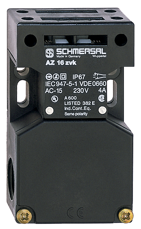
- Obudowa z tworzywa termoplastycznego
- z podwójną izolacją
- 52 mm x 90 mm x 30 mm
- Uniwersalne kodowanie
- długa żywotność
- Wysoki poziom niezawodności zestyków przy niskich napięciach i natężeniach prądu
- niewrażliwe na zabrudzenie
- Otwory szczelinowe do regulacji, otwory okrągłe do zamocowania
Klucz zamówieniowy
| Oznaczenie typu produktu |
AZ 16-02ZVRK-M16-2254 |
| Numer artykułu (Numer katalogowy) |
101156104 |
| EAN (European Article Number) |
4030661177212 |
| eCl@ss number, version 12.0 |
27-27-26-02 |
| eCl@ss number, version 11.0 |
27-27-26-02 |
| Numer eCl@ss, wersja 9.0 |
27-27-26-02 |
| ETIM number, version 7.0 |
EC002592 |
| ETIM number, version 6.0 |
EC002592 |
Certyfikaty - Normy
| Certyfikaty |
cULus CCC |
Właściwości ogólne
| Normy |
EN ISO 13849-1 EN ISO 14119 EN IEC 60947-5-1 |
| Poziom kodowania zgodny z EN ISO 14119 |
niskie |
| Zasada działania |
elektromechaniczne |
| Materiał obudowy |
Tworzywo sztuczne, tworzywo termoplastyczne wzmocnione włóknem szklanym, samogasnące |
| Ciężar brutto |
115 g |
Dane ogólne - właściwości
| Liczba kierunków aktywacji |
3 |
| Liczba zestyków bezpieczeństwa |
2 |
| Liczba dławic kablowych |
3 |
Klasyfikacja
| Normy, przepisy |
EN ISO 13849-1 |
| Performance Level, up to |
c |
| Kategoria zgodnie z EN ISO 13849 |
1 |
| B10D Normally-closed contact (NC) |
2 000 000 operacji |
| Note |
Electrical life on request. |
| Żywotność |
20 Rok(lata) |
Klasyfikacja - wykluczenie błędu
| Uwaga: |
Możliwość zastosowania po dokonaniu wykluczenia błędów w postaci niebezpiecznego uszkodzenia 1-kanałowej mechaniki i odpowiednim zabezpieczeniu przed manipulacją. |
| Poziom zapewnienia bezpieczeństwa |
d |
| Kategoria zgodnie z EN ISO 13849 |
3 |
| Note |
for 2-channel use and with suitable logic unit. |
| Żywotność |
20 Rok(lata) |
Dane mechaniczne
| Żywotność mechaniczna, najmniejszy |
1 000 000 operacji |
| Siła zatrzasku |
5 N |
| Skok wymuszonego rozwarcia |
8 mm |
| Positive break force per NC contact, minimum |
10 N |
| Siła wymuszonego rozwarcia, minimalne |
20 N |
| Szybkość najazdu, maksimum |
2 m/s |
| Montaż |
Śruby |
| Wykonanie śrub mocujących |
2 x M6 |
Mechanical data - Connection technique
| Prowadzenie przewodów |
3 x M16 x 1,5 |
| Konektor |
Terminale śrubowe |
| Przekrój kabla, minimalne |
0,25 mm² |
| Przekrój kabla, maksimum |
2,5 mm² |
| Uwaga (przekrój przyłącza) |
Wszystkie odniesienia do przekroju przewodów uwzględniają końcówki kablowe. |
| Allowed type of cable |
solid single-wire solid multi-wire flexible |
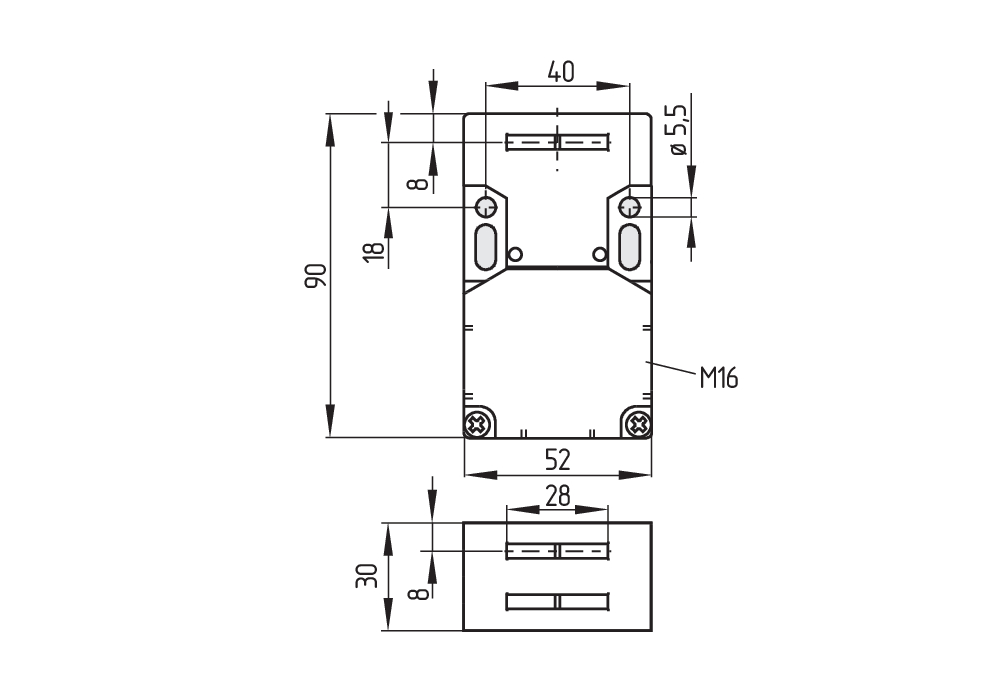
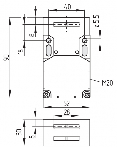
Dane mechaniczne - Wymiary
| Długość czujnika |
30 mm |
| Szerokość czujnika |
52 mm |
| Wysokość czujnika |
90 mm |
Warunki otoczenia
| Stopień ochrony |
IP67 |
| Ambient temperature |
-30 ... +80 °C |
| Storage and transport temperature |
-40 ... +85 °C |
| Dopuszczalna wysokość ustawienia n.p.m., maksimum |
2 000 m |
Ambient conditions - Insulation values
| Znamionowe napięcie izolacji |
500 V |
| Znamionowe napięcie udarowe wytrzymywane |
6 kV |
| Kategoria przepięcia |
III |
| Stopień zanieczyszczenia zgodnie z IEC/EN 60664-1 |
3 |
Dane elektryczne
| Znamionowy prąd cieplny |
10 A |
| Warunkowy znamionowy prąd zwarciowy wg EN 60947-5-1 |
1 000 A |
| Element przełączający |
Zestyk normalnie zamkniety (NC) |
| Zasada przełączania |
slow action, positive break NC contact |
| Częstotliwość przełączania |
4 000 /h |
| Materiał zestyków, elektrycznych |
Srebro |
Dane elektryczne - zestyki bezpieczeństwa
| Napięcie, kategoria użytkowania AC-15 |
230 VAC |
| Prąd, kategoria użytkowania AC-15 |
4 A |
| Napięcie, kategoria użytkowania DC-13 |
24 VDC |
| Prąd, kategoria użytkowania DC-13 |
4 A |
Zakres dostawy
| Zakres dostawy |
Actuator must be ordered separately. |
Filtr językowy
Karta katalogowa
Instrukcja obsługi (dodatek/instrukcja skrócona)
Instrukcja obsługi i deklaracja zgodności
Instrukcja obsługi i deklaracja zgodności (Short)
Certyfikat CCC
Biblioteka/Library SISTEMA-VDMA
pobierz najnowszą wersję Adobe Reader
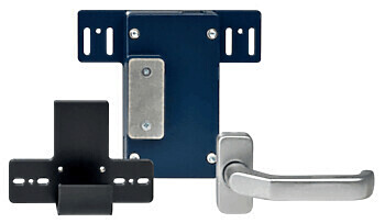
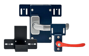
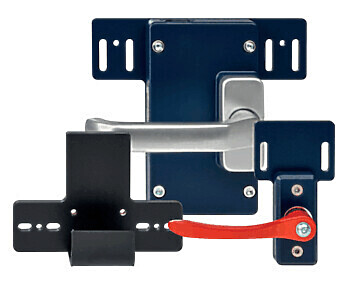
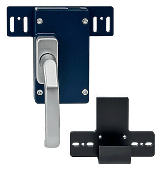
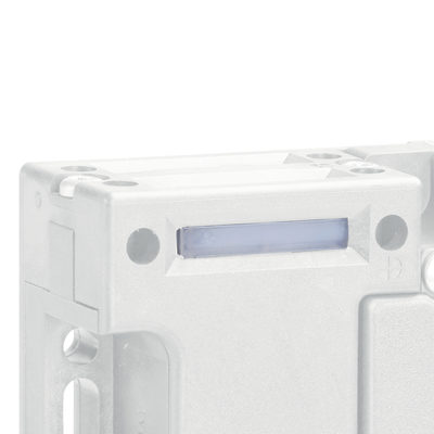
Zdjęcie produktu (pojedyncze zdjęcie katalogowe)
Rysunek wymiarowy Urządzenie podstawowe
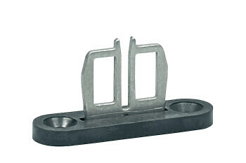
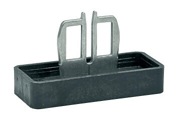
101083036 AKTYWATOR AZ 15/16-B1 KPL.
- Aktywator prosty
- nadaje się szczególnie do osłon przesuwnych

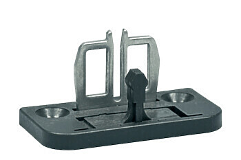
101092711 AKTYWATOR AZ 15/16-B1-1747 KPL.
- Do blokowania lekkich osłon bez jakichkolwiek luzów
- Możliwość użycia jako wyposażenie dodatkowe wyłącznika
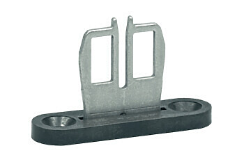
101111079 AKTYWATOR AZ 15/16-B1-2053 KPL.
- Do blokowania osłon o małym i średnim ciężarze
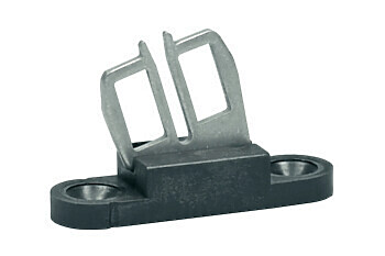
101126793 AKTYWATOR AZ 15/16-B1-2177 KPL.
- Do blokowania lekkich osłon bez prowadnic

101137408 AKTYWATOR AZ 15/16-B1-2245 KPL.
- Tłumi wibracje na urządzeniu ochronnym
- Aktywator prosty z mocowaniem gumowym
- nadaje się szczególnie do osłon przesuwnych
101095558 AKTYWATOR AZ 15/16-B2 KPL.
- Dla bardzo małych kątów najazdu wzdłuż płaszczyzny dźwigni/trzpienia
101096091 AKTYWATOR AZ 15/16-B2-1747 KPL.
- Dla bardzo małych kątów najazdu wzdłuż płaszczyzny dźwigni/trzpienia
- Możliwość użycia jako wyposażenie dodatkowe wyłącznika
- Do blokowania lekkich osłon bez jakichkolwiek luzów
101095550 AKTYWATOR AZ 15/16-B3 KPL.
- Dla bardzo małych kątów najazdu pod kątem 90° do płaszczyzny dźwigni/trzpienia
101096092 AKTYWATOR AZ 15/16-B3-1747 KPL.
- Dla bardzo małych kątów najazdu pod kątem 90° do płaszczyzny dźwigni/trzpienia
- Możliwość użycia jako wyposażenie dodatkowe wyłącznika
- Do blokowania lekkich osłon bez jakichkolwiek luzów
101137434 AKTYWATOR AZ 15/16-B6 KPL.
- Dla bardzo małych kątów najazdu wzdłuż lub pod kątem 90° do płaszczyzny dźwigni/trzpienia

101096090 AZ 15/16-B3-1747 ZESTAW WYPOSAŻENIA DODATKOWEGO
- Dla bardzo małych kątów najazdu pod kątem 90° do płaszczyzny dźwigni/trzpienia
- Możliwość użycia jako wyposażenie dodatkowe wyłącznika
- Do blokowania lekkich osłon bez jakichkolwiek luzów
- Zatrzask magnetyczny można łatwo zamocować w każdej płaszczyźnie aktywacji.

101093553 AZ 15/16-B1-1747 ZESTAW WYPOSAŻENIA DODATKOWEGO
- Do blokowania lekkich osłon bez jakichkolwiek luzów
- Zatrzask magnetyczny można łatwo zamocować w każdej płaszczyźnie aktywacji.
- Możliwość użycia jako wyposażenie dodatkowe wyłącznika
- Aktywator prosty z zatrzaskiem magnetycznym
- nadaje się szczególnie do osłon przesuwnych

101108278 AZ 15/16-B1-2024 ZESTAW WYPOSAŻENIA DODATKOWEGO
- Do ochrony przed gromadzeniem się brudu
- Aktywator prosty z uszczelką wargową
- nadaje się szczególnie do osłon przesuwnych

101111081 AZ 15/16-B1-2053 ZESTAW WYPOSAŻENIA DODATKOWEGO
- Do blokowania osłon o małym i średnim ciężarze
- Prosty aktywator z regulowanym zatrzaskiem kulkowym
- nadaje się szczególnie do osłon przesuwnych

101126794 AZ 15/16-B1-2177 ZESTAW WYPOSAŻENIA DODATKOWEGO
- Do blokowania lekkich osłon bez prowadnic

101096089 AZ 15/16-B2-1747 ZESTAW WYPOSAŻENIA DODATKOWEGO
- Dla bardzo małych kątów najazdu wzdłuż płaszczyzny dźwigni/trzpienia
- Możliwość użycia jako wyposażenie dodatkowe wyłącznika
- Do blokowania lekkich osłon bez jakichkolwiek luzów
- Zatrzask magnetyczny można łatwo zamocować w każdej płaszczyźnie aktywacji.


101089116 ZAŚLEPKA USZCZELNIAJĄCA AZ 15/16-1476
- Do ochrony przed gromadzeniem się brudu
- Do zakrycia nieużywanych szczelin aktywatora
- Łatwy montaż na zatrzask


101115025 SET BC 2053-2
- Dodatkowy zatrzask kulkowy dla stabilnego zamknięcia osłon o małym i średnim ciężarze
- Do oddzielnego montażu na osłonie

101110500 BLOKADA SERWISOWA SZ 16/335
- Dla zapobiegania nieumyślnemu zamknięciu, np. podczas konserwacji
- Do złożonych instalacji
- Zapobiega aktywacji wyłącznika
- Możliwość zamontowania do 6 kłódek
- Na łańcuchu w pobliżu wyłącznika bezpieczeństwa można umieścić blokadę serwisową.
Table of Contents
- 1 About this document
- 1.1 Function
- 1.2 Target group of the operating instructions: authorised qualified personnel
- 1.3 Explanation of the symbols used
- 1.4 Appropriate use
- 1.5 General safety instructions
- 2 Product description
- 2.1 Ordering code
- 2.2 Special versions
- 2.3 Purpose
- 2.4 Warning about misuse
- 2.5 Exclusion of liability
- 2.6 Technical Data
- 3 Mounting
- 3.1 General mounting instructions
- 3.2 Mounting of the actuator
- 3.3 Dimensions
- 4 Electrical connection
- 4.1 General information for electrical connection
- 4.2 Contact Options
- 5 Set-up and maintenance
- 6 Disassembly and disposal
- 6.1 Disassembly
- 6.2 Disposal
1 About this document
1.1 Function
This document provides all the information you need for the mounting, set-up and commissioning to ensure the safe operation and disassembly of the switchgear. The operating instructions enclosed with the device must always be kept in a legible condition and accessible.
1.2 Target group of the operating instructions: authorised qualified personnel
All operations described in the operating instructions manual must be carried out by trained specialist personnel, authorised by the plant operator only.
Please make sure that you have read and understood these operating instructions and that you know all applicable legislations regarding occupational safety and accident prevention prior to installation and putting the component into operation.
The machine builder must carefully select the harmonised standards to be complied with as well as other technical specifications for the selection, mounting and integration of the components.
The information contained in this operating instructions manual is provided without liability and is subject to technical modifications.
1.3 Explanation of the symbols used
- Information, hint, note: This symbol is used for identifying useful additional information.
- Caution: Failure to comply with this warning notice could lead to failures or malfunctions.
Warning: Failure to comply with this warning notice could lead to physical injury and/or damage to the machine.
1.4 Appropriate use
The Schmersal range of products is not intended for private consumers.
The products described in these operating instructions are developed to execute safety-related functions as part of an entire plant or machine. It is the responsibility of the manufacturer of a machine or plant to ensure the correct functionality of the entire machine or plant.
The safety switchgear must be exclusively used in accordance with the versions listed below or for the applications authorised by the manufacturer. Detailed information regarding the range of applications can be found in the chapter "Product description".
1.5 General safety instructions
The user must observe the safety instructions in this operating instructions manual, the country specific installation standards as well as all prevailing safety regulations and accident prevention rules.
- Further technical information can be found in the Schmersal catalogues or in the online catalogue on the Internet: products.schmersal.com.
2 Product description
2.1 Ordering code
| Product type description: AZ 16-(1)ZV(2)K-(3)-(4)-(5) |
| (1) | |
| without | 1 NO contacts/1 NC contact |
| 02 | 2 NC contact |
| 03 | 3 NC contact |
| 12 | 1 NO contact/2 NC contacts |
| (2) | |
| without | Ejection force |
| R | Latching force 30 N |
| (3) | |
| G24 | with LED (only available for version with one NO and one NC contact) |
| (4) | |
| M16 | cable entry M16 |
| M20 | Cable entry M20 |
| ST | Connector M12, 4 pole, bottom |
| STL | Connector M12, 4 pole, left |
| STR | Connector M12, 4 pole, right |
| (5) | |
| 2254 | Latching force 5 N |
| 1762 | Front mounting |
| 1637 | Gold-plated contacts |
2.2 Special versions
For special versions, which are not listed in the ordering code, these specifications apply accordingly, provided that they correspond to the standard version.
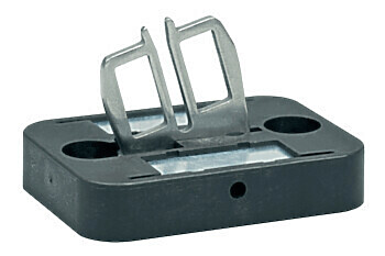
2.3 Purpose
The safety switches with separate actuator are suitable for sliding, hinged and removable safety guards, which need to be closed in order to ensure the necessary operational safety.
The safety switches are used for applications, in which the hazardous situation is terminated without delay when the safety guard is opened.
When the safety guard is opened, the NC contacts are positively opened and the NO contacts are closed.
- The safety switchgears are classified according to EN ISO 14119 as type 2 interlocking devices.
- The user must evaluate and design the safety chain in accordance with the relevant standards and the required safety level.
- The entire concept of the control system, in which the safety component is integrated, must be validated to the relevant standards.
2.4 Warning about misuse
- In case of improper use or manipulation of the safety switchgear, personal hazards or damages to machinery or plant components cannot be excluded. There are no residual risks, provided that the safety instructions as well as the instructions regarding mounting, commissioning, operation and maintenance are observed.
2.5 Exclusion of liability
We shall accept no liability for damages and malfunctions resulting from defective mounting or failure to comply with the operating instructions manual. The manufacturer shall accept no liability for damages resulting from the use of unauthorised spare parts or accessories.
For safety reasons, invasive work on the device as well as arbitrary repairs, conversions and modifications to the device are strictly forbidden, the manufacturer shall accept no liability for damages resulting from such invasive work, arbitrary repairs, conversions and/or modifications to the device.
2.6 Technical Data
Certyfikaty - Normy
| Certyfikaty |
cULus CCC |
Właściwości ogólne
| Normy |
EN ISO 13849-1 EN ISO 14119 EN IEC 60947-5-1 |
| Poziom kodowania zgodny z EN ISO 14119 |
niskie |
| Zasada działania |
elektromechaniczne |
| Materiał obudowy |
Tworzywo sztuczne, tworzywo termoplastyczne wzmocnione włóknem szklanym, samogasnące |
| Ciężar brutto |
115 g |
Dane ogólne - właściwości
| Liczba kierunków aktywacji |
3 |
| Liczba zestyków bezpieczeństwa |
2 |
| Liczba dławic kablowych |
3 |
Klasyfikacja
| Normy, przepisy |
EN ISO 13849-1 |
| Performance Level, up to |
c |
| Kategoria zgodnie z EN ISO 13849 |
1 |
| B10D Normally-closed contact (NC) |
2 000 000 operacji |
| Note |
Electrical life on request. |
| Żywotność |
20 Rok(lata) |
Klasyfikacja - wykluczenie błędu
| Uwaga: |
Możliwość zastosowania po dokonaniu wykluczenia błędów w postaci niebezpiecznego uszkodzenia 1-kanałowej mechaniki i odpowiednim zabezpieczeniu przed manipulacją. |
| Poziom zapewnienia bezpieczeństwa |
d |
| Kategoria zgodnie z EN ISO 13849 |
3 |
| Note |
for 2-channel use and with suitable logic unit. |
| Żywotność |
20 Rok(lata) |
Dane mechaniczne
| Żywotność mechaniczna, najmniejszy |
1 000 000 operacji |
| Siła zatrzasku |
5 N |
| Skok wymuszonego rozwarcia |
8 mm |
| Positive break force per NC contact, minimum |
10 N |
| Siła wymuszonego rozwarcia, minimalne |
20 N |
| Szybkość najazdu, maksimum |
2 m/s |
| Montaż |
Śruby |
| Wykonanie śrub mocujących |
2 x M6 |
Mechanical data - Connection technique
| Prowadzenie przewodów |
3 x M16 x 1,5 |
| Konektor |
Terminale śrubowe |
| Przekrój kabla, minimalne |
0,25 mm² |
| Przekrój kabla, maksimum |
2,5 mm² |
| Uwaga (przekrój przyłącza) |
Wszystkie odniesienia do przekroju przewodów uwzględniają końcówki kablowe. |
| Allowed type of cable |
solid single-wire solid multi-wire flexible |
Dane mechaniczne - Wymiary
| Długość czujnika |
30 mm |
| Szerokość czujnika |
52 mm |
| Wysokość czujnika |
90 mm |
Warunki otoczenia
| Stopień ochrony |
IP67 |
| Ambient temperature |
-30 ... +80 °C |
| Storage and transport temperature |
-40 ... +85 °C |
| Dopuszczalna wysokość ustawienia n.p.m., maksimum |
2 000 m |
Ambient conditions - Insulation values
| Znamionowe napięcie izolacji |
500 V |
| Znamionowe napięcie udarowe wytrzymywane |
6 kV |
| Kategoria przepięcia |
III |
| Stopień zanieczyszczenia zgodnie z IEC/EN 60664-1 |
3 |
Dane elektryczne
| Znamionowy prąd cieplny |
10 A |
| Warunkowy znamionowy prąd zwarciowy wg EN 60947-5-1 |
1 000 A |
| Element przełączający |
Zestyk normalnie zamkniety (NC) |
| Zasada przełączania |
slow action, positive break NC contact |
| Częstotliwość przełączania |
4 000 /h |
| Materiał zestyków, elektrycznych |
Srebro |
Dane elektryczne - zestyki bezpieczeństwa
| Napięcie, kategoria użytkowania AC-15 |
230 VAC |
| Prąd, kategoria użytkowania AC-15 |
4 A |
| Napięcie, kategoria użytkowania DC-13 |
24 VDC |
| Prąd, kategoria użytkowania DC-13 |
4 A |
Note about the safety classification
Basically suitable up to Cat. 1 / PL c.
With 2-channel usage with fault exclusion mechanism (if a fault exclusion to the 1-channel mechanics is authorised) and suitable logic applicable up to Cat. 3 / PL d

(Determined values can vary depending on the application-specific parameters hop, dop and tcycle as well as the load.)
If multiple safety components are wired in series, the Performance Level to EN ISO 13849-1 will be reduced due to the restricted error detection under certain circumstances.
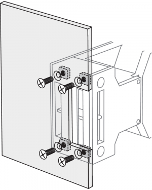
3 Mounting
3.1 General mounting instructions
- Please observe the relevant requirements of the standards ISO 12100, ISO 14119 and ISO 14120.
The mounting dimensions are indicated on the rear of the component. The enclosure must not be used as an end stop.
Any mounting position. The mounting position however must be chosen so that the ingress of dirt and soiling in the used opening is avoided. The unused openings must be sealed by means of slot sealing plugs (AZ 15/16 - 1476-1 available as accessory) after fitting.
3.2 Mounting of the actuator
See operating instructions Actuator.
- The actuator must be permanently fitted to the safety guards and protected against displacement by suitable measures (tamperproof screws, gluing, drilling of the screw heads).
| Actuating radii [mm] |  |  | ||
|---|---|---|---|---|
| over the small edge of the actuator | over the wide edge of the actuator | |||
| Rmin | d | Rmin | d | |
| AZ 15/16-B2 | - | - | 45 | 11 |
| AZ 15/16-B2-1747 | - | - | 45 | 11 |
| AZ 15/16-B3 | 32 | 11 | - | - |
| AZ 15/16-B3-1747 | 32 | 11 | - | - |
| AZ 15/16-B6 | 25 | 11 | 38 | 11 |
3.3 Dimensions
All measurements in mm.
4 Electrical connection
4.1 General information for electrical connection
- The electrical connection may only be carried out by authorised personnel in a de-energised condition.
The contact labelling can be found in the wiring compartment of the switch. Appropriate cable glands with a suitable degree of protection are to be used.
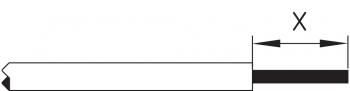
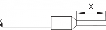
Settle length x of the conductor: 6 mm
After wiring, dust and soiling must be removed from the wiring compartment. The safety switch is double insulated. The use of a protective ground connector therefore is not authorised.
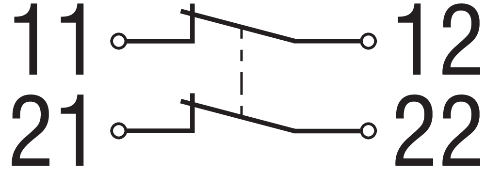
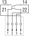
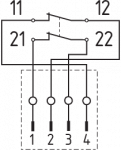
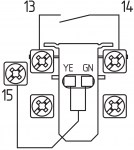
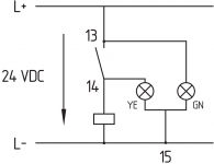
4.2 Contact Options
Contacts are shown with safety guard closed. All NC contacts have positive break B.
| AZ 16ZV.K | AZ 16-02ZV.K | AZ 16-12ZV.K |
|---|---|---|
 |  |  |
| AZ 16-03ZV.K | AZ 16ZV.K-ST | AZ 16-02ZV.K-ST |
|---|---|---|
 |  |  |
| AZ 16-12ZV.K-ST | LED | LED |
|---|---|---|
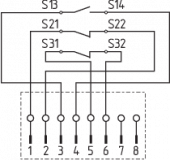 |  |  |
| Key | |
|---|---|
| B | Automatic opener, NC contact |
 | Normally-open contact |
 | Normally-closed contact |
5 Set-up and maintenance
The safety function of the safety components must be tested. In the case of correct installation and adequate use, the safety switchgear features maintenance-free functionality. A regular visual inspection and functional test, including the following steps, is recommended:
- Check for free movement of the actuating element
- Check cable entry and connections
- Check the switch enclosure for damage
- Remove particles of dust and soiling
- Adequate measures must be taken to ensure protection against tampering either to prevent tampering of the safety guard, for instance by means of replacement actuators.
- Damaged or defective components must be replaced.
6 Disassembly and disposal
6.1 Disassembly
The safety switchgear must be disassembled in a de-energised condition only.
6.2 Disposal
- The safety switchgear must be disposed of in an appropriate manner in accordance with the national prescriptions and legislations.
| EU-Konformitätserklärung |  |
| Original | K.A. Schmersal GmbH & Co. KG Möddinghofe 30 42279 Wuppertal Germany Internet: www.schmersal.com |
| Erklärung: | Hiermit erklären wir, dass die nachfolgend aufgeführten Bauteile aufgrund der Konzipierung und Bauart den Anforderungen der unten angeführten Europäischen Richtlinien entsprechen. |
| Bezeichnung des Bauteils: | AZ 15 AZ 16 |
| Typ: | siehe Typenschlüssel |
| Beschreibung des Bauteils: | Zwangsöffnender Positionsschalter mit getrenntem Betätiger für Sicherheitsfunktionen |
| Einschlägige Richtlinien: | Maschinenrichtlinie | 2006/42/EG |
| RoHS-Richtlinie | 2011/65/EU |
| Angewandte Normen: | EN 60947-5-1:2017 ISO 14119:2013 |
| Bevollmächtigter für die Zusammenstellung der technischen Unterlagen: | Oliver Wacker Möddinghofe 30 42279 Wuppertal |
| Ort und Datum der Ausstellung: | Wuppertal, 3. August 2020 |
 |
| Rechtsverbindliche Unterschrift Philip Schmersal Geschäftsführer |
| UK Declaration of Conformity | |
| Company: | K.A. Schmersal GmbH & Co. KG Möddinghofe 30 42279 Wuppertal Germany Internet: www.schmersal.com |
| Declaration: | We hereby, under sole responsibility, certify that the hereafter described components both in their basic design and construction conform to the relevant statutory requirements, regulations and designated standards of the United Kingdom. |
| Name of the component: | AZ 15 AZ 16 |
| Type: | See ordering code |
| Description of the component: | Positive break position switch with separate actuator for safety functions |
| Relevant legislation: | Supply of Machinery (Safety) Regulations The Restriction of the Use of Certain Hazardous Substances in Electrical and Electronic Equipment Regulations | 2008 2012 |
| Designated standards: | EN 60947-5-1: 2017 ISO 14119: 2013 |
| UK-Importer / Person authorised for the compilation of the technical documentation: | Schmersal UK Ltd. Paul Kenney Unit 1, Sparrowhawk Close Enigma Business Park Malvern, Worcestershire, WR14 1GL |
| Place and date of issue: | Wuppertal, October 28, 2022 |
|
| Authorised signature Philip Schmersal Managing Director |
Schmersal-Polska Sp.j., ul. Baletowa 29, 02-867 Warszawa
Dane zostały starannie sprawdzone. Zdjęcia mogą odbiegać od rzeczywistości. Dalsze dane techniczne znajdują się w instrukcji obsługi. Możliwe są zmiany i błędy techniczne.
Wygenerowano dnia 18.04.2024, 13:47