This document provides all the information you need for the mounting, set-up and commissioning to ensure the safe operation and disassembly of the switchgear. The operating instructions enclosed with the device must always be kept in a legible condition and accessible.
All operations described in the operating instructions manual must be carried out by trained specialist personnel, authorised by the plant operator only.
Please make sure that you have read and understood these operating instructions and that you know all applicable legislations regarding occupational safety and accident prevention prior to installation and putting the component into operation.
The machine builder must carefully select the harmonised standards to be complied with as well as other technical specifications for the selection, mounting and integration of the components.
The information contained in this operating instructions manual is provided without liability and is subject to technical modifications.
The Schmersal range of products is not intended for private consumers.
The products described in these operating instructions are developed to execute safety-related functions as part of an entire plant or machine. It is the responsibility of the manufacturer of a machine or plant to ensure the correct functionality of the entire machine or plant.
The safety switchgear must be exclusively used in accordance with the versions listed below or for the applications authorised by the manufacturer. Detailed information regarding the range of applications can be found in the chapter "Product description".
The user must observe the safety instructions in this operating instructions manual, the country specific installation standards as well as all prevailing safety regulations and accident prevention rules.
| Product type description: AZM300(1)-(2)-ST-(3)-(4)-(5) |
| (1) | |
| Z | Guard locking monitored > |
| B | Actuator monitored |
| (2) | |
| without | Standard coding |
| I1 | Individual coding |
| I2 | Individual coding, multiple teaching |
| (3) | |
| 1P2P | 1 p-type diagnostic output and 2 p-type safety outputs |
| SD2P | serial diagnostic output and 2 p-type safety outputs |
| (4) | |
| without | Power to unlock |
| A | Power to lock |
| (5) | |
| without | Manual release |
| N | Emergency release |
| T | Emergency exit |
| T 8 | Emergency exit, distance 8.5 mm |
For special versions, which are not listed in the ordering code, these specifications apply accordingly, provided that they correspond to the standard version.
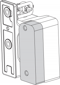
The non-contact, electronic safety switchgear is designed for application in safety circuits and is used for monitoring the position and locking of movable safety guards.
The different variants can be used as safety switch with interlocking function either as solenoid interlock.
The safety function consists of safely switching off the safety outputs when the safety guard is unlocked or opened and maintaining the safe switched off condition of the safety outputs for as long as the safety guard is open.
We shall accept no liability for damages and malfunctions resulting from defective mounting or failure to comply with the operating instructions manual. The manufacturer shall accept no liability for damages resulting from the use of unauthorised spare parts or accessories.
For safety reasons, invasive work on the device as well as arbitrary repairs, conversions and modifications to the device are strictly forbidden, the manufacturer shall accept no liability for damages resulting from such invasive work, arbitrary repairs, conversions and/or modifications to the device.
|
TÜV cULus ECOLAB FCC IC UKCA ANATEL |
| Instruções |
EN ISO 13849-1 EN ISO 14119 EN IEC 60947-5-3 EN IEC 61508 |
| informação gerais |
Codificação universal |
| Nível de codificação conforme EN ISO 14119 |
baixa |
| Princípio ativo |
RFID |
| Banda de frequência RFID |
125 kHz |
| Potência de envio RFID, máximo |
-6 dB/m |
| Material do invólucro |
Plástico, termoplástico reforçado com fibra de vidro |
| Tempo de risco, máximo |
200 ms |
Tempo de reação das saídas de segurança em caso de desconexão por atuador, máximo tempo de reação das saídas de segurança em caso de desconexão pelas entradas de segurança, máximo |
100 ms |
Tempo de reação das saídas de segurança em caso de desconexão pelas entradas de segurança, máximo |
1,5 ms |
| Peso bruto |
600 g |
| Princípio de bloqueio por corrente elétrica |
Sim |
| Supervisão de atuadores |
Sim |
| Bloqueio |
Sim |
| Desbloqueio auxiliar |
Sim |
| Deteção de curto-circuito |
Sim |
| Reconhecimento de curto-circuito |
Sim |
| Ligação em série |
Sim |
| Funções de segurança |
Sim |
| Indicação integrada, estado |
Sim |
| Número de direções de atuação |
3 |
| Quantidade de saídas digitais seguras |
2 |
| Certificados |
EN ISO 13849-1 EN IEC 61508 |
| Performance Level, até |
e |
| Categoria de comando |
4 |
| Valor PFH |
5,20 x 10⁻¹⁰ /h |
| Valor PFD |
4,50 x 10⁻⁵ |
| Safety Integrity Level (SIL), apropriado para aplicações em |
3 |
| Vida útil |
20 Jahr(e) |
| Resistência mecânica, Mínimo |
1 000 000 Schaltspiele |
| Orientação (resistência mecânica) |
Para utilização como dobradiça de porta: ≥ 50.000 operações (para proteções ≤ 5 kg e velocidade do atuador ≤ 0,5 m/s) |
| Desalinhamento angular entre solenoide e atuador, máximo |
2 ° |
| Força de engate FZh segundo a EN ISO 14119 |
1 150 N |
| Força de engate Fmax, máximo |
1 500 N |
| Força de retenção, ajustável, posição 1 |
25 N |
| Força de retenção, ajustável, posição 2 |
50 N |
| Versão dos parafusos de fixação |
2x M6 |
| Binário de aperto dos parafusos de fixação, mínimo |
6 Nm |
| Binário de aperto para parafusos de fixação, máximo |
7 Nm |
| Distância do interruptor, típico |
2 mm |
| Distância do interruptor garantida "ON" Sao |
1 mm |
| Distância do interruptor garantida "OFF" Sar |
20 mm |
| Nota (distância do interruptor) |
All switching distances in accordance EN IEC 60947-5-3 |
| Comprimento da corrente de sensores, máximo |
200 m |
| Nota (comprimento da cadeia de sensores) |
O comprimento e a secção do cabo alteram a queda de tensão em função da corrente de saída |
| Nota (ligação em série) |
Número ilimitado de dispositivos, respeitar a proteção externa do condutor, máx. 31 dispositivos com diagnóstico serial SD |
| Tipo de conexão |
Conector M12, 8-polos, codificação-A |
| Comprimento de sensor |
120 mm |
| Largura de sensor |
87,5 mm |
| Altura do sensor |
35 mm |
| Tipo de proteção |
IP66 IP67 IP69 |
| Temperatura ambiente |
+0 ... +60 °C |
| Temperatura para armazenar e transportar |
-10 ... +90 °C |
| Humidade relativa, máximo |
93 % |
| Orientação (humidade relativa) |
não condensado sem gelo |
| Resistência à vibração |
10 … 150 Hz, amplitude 0,35 mm |
| Resistência a impactos |
30 g / 11 ms |
| Classe de proteção |
III |
| Altura de instalação permitida sobre NN, máximo |
3 000 m |
| Tensão calculada de isolamento Ui |
32 VDC |
| Medição da rigidez dielétrica da tensão máxima Uimp |
0,8 kV |
| Categoria de sobre-tensão |
III |
| Grau de contaminação por sujeira |
3 |
| Tensão de operação |
24 VDC -15 % / +10 % (fonte de alimentação PELV) |
| Corrente de circuito aberto I0, típico |
100 mA |
| Consumo de corrente com o íman ON, valor médio |
200 mA |
| Consumo de corrente com íman ON, valor de pico |
350 mA / 200 ms |
| Medição da tensão de operação |
24 VDC |
| Corrente operacional nominal |
800 mA |
| Corrente de curto-circuito |
100 A |
| Isolação externa de cabos e equipamento |
2A gG |
| Atraso na operação, máximo |
5 000 ms |
| Frequência de comutação, máximo |
0,5 Hz |
| Categoria de aplicação DC-12 |
24 VDC / 0,05 A |
| Dados elétricos, máximo |
2 A |
| Designação, comando magnético |
IN |
| Limiares de comutação |
-3 V … 5 V (Low) 15 V … 30 V (High) |
| Potência instalada a 24 V |
10 mA |
| Ciclo de carga do íman |
100 % |
| Duração do impulso de teste, máximo |
5 ms |
| Intervalo do impulso de teste, mínimo |
40 ms |
| Classificação ZVEI CB24I, descida |
C0 |
| Classificação ZVEI CB24I, fonte |
C1 C2 C3 |
| Designação, entradas de segurança |
X1 e X2 |
| Limiares de comutação |
−3 V … 5 V (Low) 15 V … 30 V (High) |
| Potência instalada a 24 V |
5 mA |
| Duração do impulso de teste, máximo |
1 ms |
| Intervalo do impulso de teste, mínimo |
100 ms |
| Classificação ZVEI CB24I, descida |
C1 |
| Classificação ZVEI CB24I, fonte |
C1 C2 C3 |
| Designação, saídas de segurança |
Y1 e Y2 |
| Versão de elementos de comutação |
À prova de curto-circuito, tipo p |
| Queda de tensão Ud, máximo |
2 V |
| Corrente residual Ir, máximo |
0,5 mA |
| Voltagem, categoria de aplicação DC-12 |
24 VDC |
| Potência, categoria de aplicação DC-12 |
0,25 A |
| Voltagem, categoria de aplicação DC-13 |
24 VDC |
| Potência, categoria de aplicação DC-13 |
0,25 A |
| Intervalo do impulso de teste, típico |
1000 ms |
| Duração do impulso de teste, máximo |
0,5 ms |
| Classificação ZVEI CB24I, fonte |
C2 |
| Classificação ZVEI CB24I, descida |
C1 C2 |
| Designação, saídas de diagnóstico |
OUT |
| Versão de elementos de comutação |
À prova de curto-circuito, tipo p |
| Queda de tensão Ud, máximo |
2 V |
| Voltagem, categoria de aplicação DC-12 |
24 VDC |
| Potência, categoria de aplicação DC-12 |
0,05 A |
| Voltagem, categoria de aplicação DC-13 |
24 VDC |
| Potência, categoria de aplicação DC-13 |
0,05 A |
| Orientação (LED indicador do estado) |
Estado operacional : LED amarelo Falha avaria funcional: LED vermelho Tensão de alimentação UB: LED verde indica |
| PIN 1 |
A1 Tensão de alimentação UB |
| PIN 2 |
X1 Entrada de segurança 1 |
| PIN 3 |
A2 GND |
| PIN 4 |
Y1 Saída de segurança 1 |
| PIN 5 |
OUT Saída para diagnóstico |
| PIN 6 |
X2 Entrada de segurança 2 |
| PIN 7 |
Y2 Saída de segurança 2 |
| PIN 8 |
IN Comando magnético |
Note about the safety classification
UL notice
FCC/IC - Note
This device complies with Part 15 of the FCC Rules and contains licence-exempt transmitter/receivers that are compliant with ISED (Innovation, Science and Economic Development) Canada licence-exempt RSS standard(s).
Operation is subject to the following two conditions:
(1) This device may not cause harmful interference signals, and
(2) This device must be able to tolerate interference signals. These also include interference signals that could cause the device to function improperly.
This device complies with the nerve stimulation limits (ISED SPR-002) when operated at a minimum distance of 100 mm. Changes or modifications not expressly approved by K.A. Schmersal GmbH & Co. KG could void the user's authority to operate the equipment.
The licence-free transmitter/receiver contained in this device satisfies the requirements of the "Radio Standards Specification" of the Innovation, Science and Economic Development Canada (ISED) authority that apply to licence-free radio equipment. Operation is permissible under the following two conditions:
(1) The device must not create disturbances.
(2) The device must tolerate received radio frequency interference, even if this could impair its functionality.
This device complies with the nerve stimulation limits (ISED CNR-102) when operated at a minimum distance of 100 mm.
In the event of changes or modifications that have not been expressly approved by K.A. Schmersal GmbH & Co. KG, the user's authorisation to use the device may become ineffective.
| 20941-22-14519 | Este equipamento nao tem direito àprotecao contra interferência prejudicial e nao pode causar interferencia em sistemas devidamente autorizados. Para maiores informacores consultar: www.gov.br/anatel |
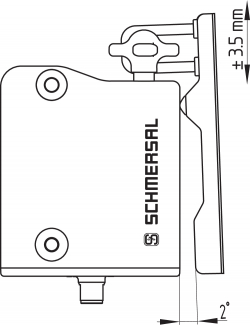
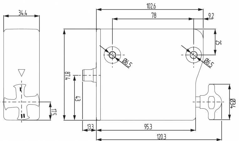
For the correct fixing of the solenoid interlock and the actuator, two mounting holes for M6 screws are provided (tightening torque: 6 … 7 Nm).
Any mounting position. The system must only be operated with an angle of ≤ 2° between the solenoid interlock and the actuator.

Mounting of the actuators
Refer to the mounting instructions manual for the corresponding actuator.
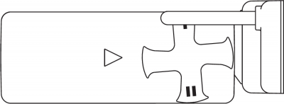
Actuating directions


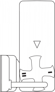
The diagrams show a closed guard system with a set latching force of 50 N (see also chapter "adjustment of latching force").
Correct
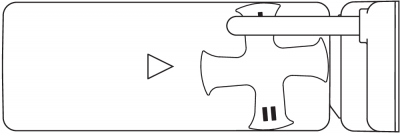
False
To avoid any interference inherent to this kind of system and any reduction of the switching distances, please observe the following guidelines:
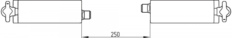
Minimum distance between two solenoid interlocks
as well as other systems with same frequency (125 kHz)

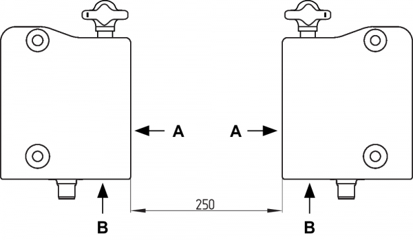
The minimum distance from metallic securing surfaces to the face side "A" and underside "B" of the device is 5 mm.

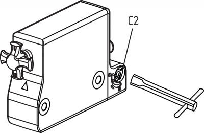
For the machine set-up, the solenoid interlock can be unlocked in a de-energised condition. The solenoid interlock is unlocked by turning the manual release in the position q The normal locking function is only restored after the manual release has been returned to its original position p.
Caution: do not turn beyond the end stop!

Key
A: connector plug M12, 8-pole
B: LED display
C1: Manual release by means of slotted screwdriver
C2: Manual release by means of triangular key TK-M5
The manual release must be protected against accidental actuation, e.g. by using the enclosed seal after completing commissioning.
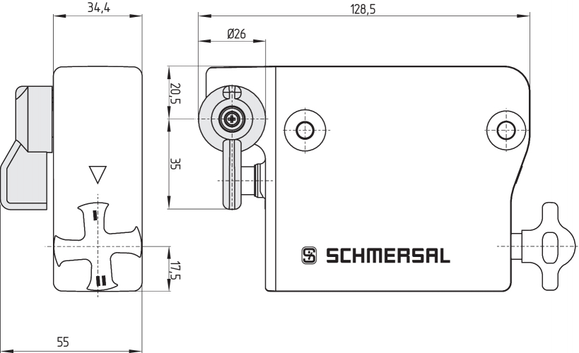
With variants that have both emergency exit and emergency release, the red lever is loosely supplied. Before first use, mount the lever on the triangular part of the release using the screw supplied so that the arrow in the triangle and pin on the red lever are congruent.
The installation of the lever is possible on both sides. The opposite side can be used as a manual release by means of a triangular key TK-M5.
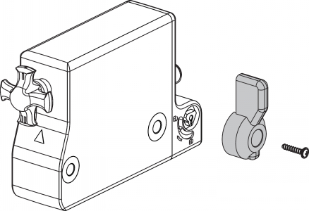
To activate the emergency exit, turn the red lever in the direction of the arrow to the end stop. The safety outputs switch off and the guard system can be opened. The blocked position is cancelled by turning the lever in the opposite direction. In the unlocked position, the guard system is secured against unintentional locking.
To activate the emergency release turn the red lever in the direction of the arrow to the end stop. The safety outputs switch off and the guard system can be opened. The lever is latched and cannot be returned to its original position. To cancel the blocking condition, the central mounting screw must be loosened to such extent that the lever can be turned back into its original position. The screw must then be re-tightened.
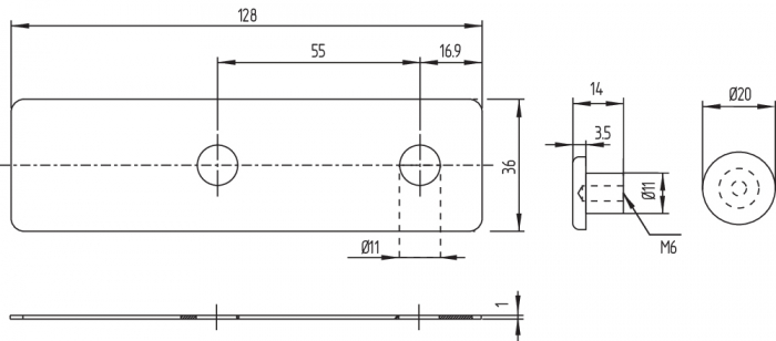
For doors, which close flush with the door frame, the optional mounting late MP-AZ/AZM300-1 can be used.

All measurements in mm.
AZM300...-T/-T8 and -N
Device with emergency exit or emergency release
Emergency exit -T / Emergency release -N
Emergency exit -T8

Actuator AZ/AZM300-B1 (not included in delivery)
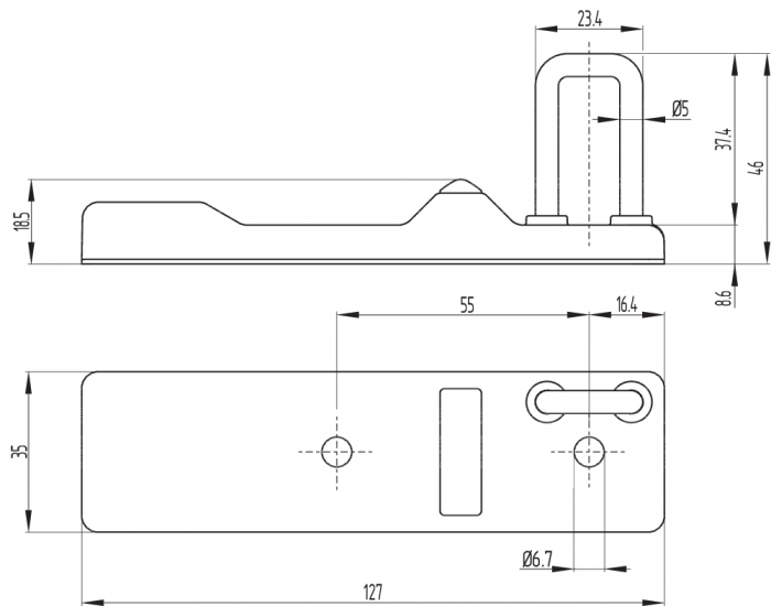
Mounting plate MP-AZ/AZM300-1 (available as accessory)

MS-AZ/AZM300-B1-1 (available as accessory)
Aluminium protective plate as a cover for use on glass and plastic doors on machines with high design requirements
Lockout tag SZ 200-1 (available as accessory)

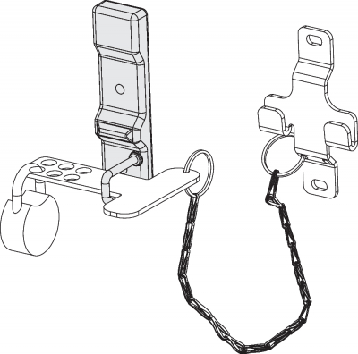
Bowden cable release ACC-AZM300-BOW-.-.M-.M (available as accessory)
Observe the additional notes in the operating instructions of the Bowden cable release.

The voltage inputs A1, X1, X2 and IN must have a protection against permanent overvoltage. Supply units according to EN 60204-1 is recommended.
The required electrical cable fuse protection must be integrated in the installation.
The safety outputs can be integrated into the safety circuit of the control system.
Requirements for the connected safety-monitoring module:
Dual-channel safety input, suitable for 2 p-type semi-conductor outputs
Cable design
The wiring capacity of the connecting cable of the solenoid interlock must not exceed 50 nF. Depending on the strand structure, normal unshielded 30 m long control cables LIYY 0.25 mm² to 1.5 mm² have a wiring capacitance of approx. 3 … 7 nF.
Series-wiring can be set up. In the case of a series connection, the risk time remains unchanged and the reaction time increases by the sum of the reaction time of the inputs per additional unit specified in the technical data. The quantity of devices is only limited by the cable drops and the external cable fuse protection, according to the technical data. Series-wiring of up to 31 AZM300 … SD components with serial diagnostics is possible.
The application examples shown are suggestions. They however do not release the user from carefully checking whether the switchgear and its set-up are suitable for the individual application. The application examples shown are suggestions.
Wiring example 1: Series-wiring of the AZM300 with conventional diagnostic output
The voltage is supplied at both safety inputs of the terminal safety component of the chain (considered from the safety-monitoring module). The safety outputs of the first safety component are wired to the safety-monitoring module.
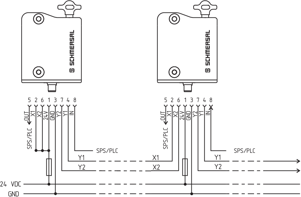
Y1 and Y2 = Safety outputs → Safety monitoring module
Wiring example 2: Series-wiring of the AZM300 with serial diagnostic function (max. 31 components in series)
In devices with the serial diagnostics function (ordering suffix -SD), the serial diagnostics connections are wired in series and connected to a SD-Gateway for evaluation purposes. The safety outputs of the first safety component are wired to the safety-monitoring module. The serial Diagnostic Gateway is connected to the serial diagnostic input of the first safety component.
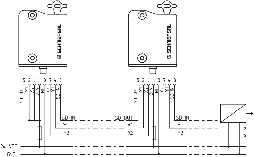
Y1 and Y2 = Safety outputs → Safety monitoring module
SD-IN → Gateway → Field bus
| Function safety switchgear | Pin configuration of the connector | Colour codes of the Schmersal connectors | Poss. colour code of other commercially available connectors according to EN 60947-5-2 | |||
|---|---|---|---|---|---|---|
| With conventional diagnostic output | With serial diagnostic function |  | IP67 / IP69 to DIN 47100 | IP69 (PVC) | ||
| A1 | Ue | 1 | WH | BN | BN | |
| X1 | Safety input 1 | 2 | BN | WH | WH | |
| A2 | GND | 3 | GN | BU | BU | |
| Y1 | Safety output 1 | 4 | YE | BK | BK | |
| OUT | Diagnostic output | SD-output | 5 | GY | GY | GY |
| X2 | Safety input 2 | 6 | PK | VT | PK | |
| Y2 | Safety output 2 | 7 | BU | RD | VT | |
| IN | Solenoid control | SD-input | 8 | RD | PK | OR |
| Connecting cables with coupling (female) IP67 / IP69, M12, 8-pole - 8 x 0.25 mm² to DIN 47100 | |
|---|---|
| Cable length | Ordering code |
| 2,5 m | 103011415 |
| 5,0 m | 103007358 |
| 10,0 m | 103007359 |
| 15,0 m | 103011414 |
| Connecting cables (PVC) with socket (female) M12, 8-pole - 8 x 0.21 mm², IP69 | |
|---|---|
| Cable length | Ordering code |
| 5.0 m | 101210560 |
| 5.0 m, angled | 101210561 |
| 10.0 m | 103001389 |
| 15.0 m | 103014823 |
Solenoid interlocks with standard coding are ready to use upon delivery.
Individually coded solenoid interlocks and actuators will require the following "teach-in" procedure:
For ordering suffix -I1, the executed allocation of safety switchgear and actuator is irreversible.
For ordering suffix -I2, the "teach-in" procedure for a new actuator can be repeated an unlimited number of times. When a new actuator is taught, the code, which was applicable until that moment, becomes invalid. Subsequent to that, an enabling inhibit will be active for ten minutes, thus providing for an increased protection against tampering. The green LED will flash until the expiration of the time of the enabling inhibit and the detection of the new actuator. In case of power failure during the lapse of time, the 10-minutes tampering protection time will restart.
In order to enable trouble-free functionality of the device, the rotary handle must be in position I or II when the safety guard is open. In the intermediate positions, locking is impossible. The latching force is changed by turning the rotary handle by 180°.
In position I,the latching force is approx. 25 N.
In position II, the latching force is approx. 50 N.

In the power to unlock version of the AZM300, the solenoid interlock is unlocked when the IN signal (= 24V) is set. In the power to lock version of the AZM300, the solenoid interlock is locked when the IN signal (= 24 V) is set.
In the standard AZM300Z variant, the unlocking of the solenoid interlock causes the safety outputs to be disabled. The unlocked safety guard can be relocked as long as the actuator is inserted in the AZM300Z solenoid interlock; in that case, the safety outputs are re-enabled.
It is not necessary to open the safety guard.
In the AZM300B version, only the opening of the safety guard causes the safety outputs to be disabled.
The solenoid interlock signals the operating condition, as well as errors through 3-colour LEDs.
| green (Power) | Supply voltage on |
| yellow (Status) | Operating condition |
| red (Fault) | Error (see table 2: Error messages / flash codes red diagnostic LED) |
| System condition No input signal at X1 and/or X2 | LED | ||
|---|---|---|---|
| green | red | yellow | |
| Safety guard open and a safety guard in the safety circuit upstream is also open | Flashes (1 Hz) | Off | Off |
| Safety guard closed and a safety guard in the safety circuit upstream is open | Flashes (1 Hz) | Off | Flashes |
| Safety guard locked and a safety guard in the safety circuit upstream is open | Flashes (1 Hz) | Off | On |
The short-circuit proof diagnostic output OUT can be used for central visualisation or control tasks, e.g. in a PLC.
The diagnostic output is not a safety-related output.
Error
Errors which no longer guarantee the function of the safety switchgear (internal errors) cause the safety outputs to be disabled within the duration of risk. After fault rectification, the error message is reset by opening and re-closing the corresponding safety guard.
Fault warning
A fault that does not immediately endanger the safety function of the safety switchgear (e.g. too high ambient temperature, safety output at external potential, cross-circuit) leads to delayed shutdown (see Table 2). This signal combination, diagnostic output disabled and safety channels still enabled, can be used to stop the production process in a controlled manner. An error warning is deleted when the cause of error is eliminated. If the fault warning remains on for 30 minutes, the safety outputs are also switched off (red LED flashes, see Table 2).
Behaviour of diagnosis output based on interlock with power to unlock as an example
Input signal magnet control

Normal sequence, door was locked

Door could not be locked or fault

 | Safety guard open |  | Safety guard closed |  | Locking time |
 | Safety guard not locked or fault |  | Safety guard locked | ||
 | Lock |  | Unlock |
Evaluation of diagnostic output

Power to unlock: IN = 0 = Lock
 | Safety guard can be locked |
 | Safety guard locked |
Power to lock: IN = 1 = Lock
 | Safety guard can be locked |
 | Safety guard locked |
| Table 1: Diagnostic information of the safety switchgear | ||||||||
|---|---|---|---|---|---|---|---|---|
| System condition | Magnet control IN | LED | Safety outputs Y1, Y2 | Diagnostic output OUT | ||||
| Power to unlock | Power to lock | green | red | yellow | AZM300Z | AZM300B | ||
| Safety guard open | 24 V (0 V) | 0 V (24 V) | On | Off | Off | 0 V | 0 V | 0 V |
| Safety guard closed, not locked | 24 V | 0 V | On | Off | Flashes | 0 V | 24 V | 24 V |
| Safety guard closed, locking impossible | 0 V | 24 V | On | Off | Flashes | 0 V | 24 V | 0 V |
| Safety guard closed and locked | 0 V | 24 V | On | Off | On | 24 V | 24 V | 24 V |
| Error warning1) | 0 V | 24 V | On | Flashes2) | On | 24 V1) | 24 V1) | 0 V |
| Error | 0 V (24 V) | 24 V (0 V) | On | Flashes2) | Off | 0 V | 0 V | 0 V |
| No input signal at X1 and/or X2 | 0 V (24 V) | 24 V (0 V) | Flashes | Off | Off | 0 V | 0 V | 0 V |
| No input signal at X1 and/or X2 | 0 V (24 V) | 24 V (0 V) | Flashes | Off | On/Flashes | 0 V | 0 V | 24 V |
| Additionally for variant I1/I2: | ||||||||
| Teach-in procedure actuator started | Off | On | Flashes | 0 V | 0 V | 0 V | ||
| Only I2: teach-in procedure actuator (release block) | Flashes | Off | Off | 0 V | 0 V | 0 V | ||
1) after 30 min: disabling due to fault 2) refer to flash code | ||||||||
| Table 2: Error messages / flash codes red diagnostic LED | |||
|---|---|---|---|
| Flash pulses (red) | Designation | Autonomous switch-off after | Error cause |
| 1 flash pulse | Error (warning) at output Y1 | 30 min | Fault in output test or voltage at output Y1, although the output is disabled. |
| 2 flash pulses | Error (warning) at output Y2 | 30 min | Fault in output test or voltage at output Y2, although the output is disabled. |
| 3 flash pulses | Error (warning) cross-wire short | 30 min | Cross-wire short between the output cables or fault at both outputs |
| 4 flash pulses | Error (warning) temperature too high | 30 min | The temperature measurement reveals an internal temperature that is too high |
| 5 flash pulses | Actuator fault | 0 min | Incorrect or defective actuator, bracket broken, Malfunction of the RFID signal |
| 6 flash pulses | Fault rotary handle | 0 min | Rotary handle not in authorised intermediate position |
| Continuous red signal | Internal error | 0 min | Device defective |
Solenoid interlocks with serial diagnostic cable have a serial input and output cable instead of the conventional diagnostic output. If solenoid interlocks are wired in series, the diagnostic data are transmitted through the series-wiring of the inputs and outputs.
Max. 31 solenoid interlocks can be wired in series. For the evaluation of the serial diagnostics line either the PROFIBUS-Gateway SD-I-DP-V0-2 or the Universal-Gateway SD-I-U-... are used. This serial diagnostic interface is integrated as slave in an existing field bus system. In this way, the diagnostic signals can be evaluated by means of a PLC.
The necessary software for the integration of the SD-Gateway is available for download at products.schmersal.com.
The response data and the diagnostic data are automatically and permanently written in an input byte of the PLC for each solenoid interlock in the series-wired chain. The request data for each solenoid interlock is transmitted to the component through an output byte of the PLC. In case of a communication error between the SD-gateway and the solenoid interlock, the switching condition of the solenoid interlock is maintained.
Error
Errors which no longer guarantee the function of the safety switchgear (internal errors) cause the safety outputs to be disabled within the duration of risk. The fault is reset, when the cause is eliminated and bit 7 of the request byte changes from 1 to 0 or the safety guard is opened. Faults at the safety outputs are only deleted upon the next release, as the fault rectification cannot be detected sooner.
Fault warning
A fault that does not immediately endanger the safety function of the safety switchgear (e.g. too high ambient temperature, safety output at external potential, cross-circuit) leads to delayed shutdown (see Table 2). This signal combination, diagnostic output disabled and safety channels still enabled, can be used to stop the production process in a controlled manner. An error warning is deleted when the cause of error is eliminated. If the fault warning remains on for 30 minutes, the safety outputs are also switched off (red LED flashes, see Table 2).
Diagnostic error (warning)
If an error (warning) is signalled in the response byte, detailed fault information can be read out.
| Table 3: I/O data and diagnostic data (The described condition is reached, when Bit = 1) | ||||
|---|---|---|---|---|
| Bit n° | Call Byte | Response-Byte | Diagnostic error warning | Diagnostic error |
| Bit 0: | Magnet on, irrespective of power to lock or power to unlock principle | Safety output activated | Error output Y1 | Error output Y1 |
| Bit 1: | --- | Safety guard closed AND locking/unlocking possible 1) | Error output Y2 | Error output Y2 |
| Bit 2: | --- | Actuator detected and locked | Cross-wire short | Cross-wire short |
| Bit 3: | --- | --- | Temperature too high | Temperature too high |
| Bit 4: | --- | Input condition X1 and X2 | --- | Incorrect or defective actuator, bracket broken, Malfunction of the RFID signal |
| Bit 5: | --- | Valid actuator detected | Internal device error | Internal device error |
| Bit 6: | --- | Error warning 2) | Communication error between the field bus Gateway and the safety switchgear | --- |
| Bit 7: | Error reset | Error (enabling path switched off) | Rotary handle not in authorised intermediate position | Rotary handle not in authorised intermediate position |
| 1) The leading diagnosis message through bit 1 indicates whether locking or unlocking of the guard system is possible. The solenoid interlock cannot be unlocked if e.g. the door pulls the turret out of its rest position beyond the set latching force. This can occur if doors are heavily distorted or when pulling the door. The solenoid interlock can only be locked if the turret is in the rest position, i.e. the latching force is sufficient to pull the guard system into the correct position. 2) after 30 min -> fault | ||||
The safety function of the safety components must be tested. In the case of correct installation and adequate use, the safety switchgear features maintenance-free functionality. A regular visual inspection and functional test, including the following steps, is recommended:
The safety switchgear must be disassembled in a de-energised condition only.