AES 1136-2185
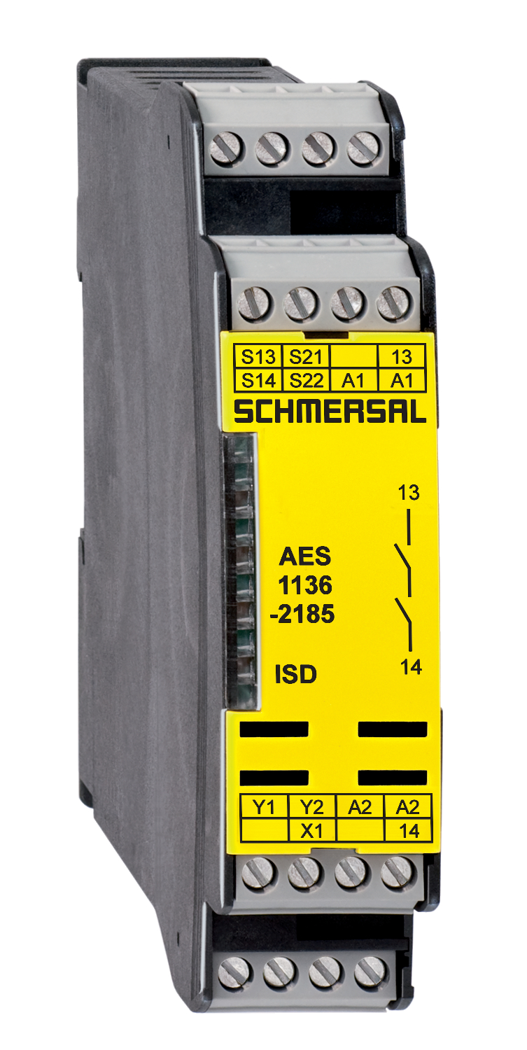
AES 1136-2185
- Monitoring of BNS range magnetic safety sensors
- 1 safety contact, STOP 0
- 2 Signalling outputs
Ordering data
| Note (Delivery capacity) |
Elde mevcut değil! |
| Product type description |
AES 1136-2185 |
| Article number (order number) |
101172221 |
| EAN (European Article Number) |
4030661300450 |
| eCl@ss number, version 12.0 |
27-37-18-19 |
| eCl@ss number, version 11.0 |
27-37-18-19 |
| eCl@ss number, version 9.0 |
27-37-18-19 |
| ETIM number, version 7.0 |
EC001449 |
| ETIM number, version 6.0 |
EC001449 |
| Available until |
31.12.2024 |
Approvals - Standards
| Certificates |
cULus |
General data
| Standards |
BG-GS-ET-14 BG-GS-ET-20 EN IEC 62061 EN ISO 13849-1 EN IEC 60947-5-1 EN IEC 60947-5-3 EN IEC 60947-5-5 EN IEC 60204-1 EN IEC 60947-1 |
| Climatic stress |
EN 60068-2-3 BG-GS-ET-14 |
| Housing material |
Plastik, fiber cam takviyeli termoplastik, havalandırılmış |
| Gross weight |
190 g |
General data - Features
| Wire breakage detection |
Evet |
| Cross-circuit detection |
Evet |
| Automatic reset function |
Evet |
| Start-up test |
Evet |
| Earth connection detection |
Evet |
| Integral system diagnostics, status |
Evet |
| Number of LEDs |
1 |
| Number of normally closed (NC) |
2 |
| Number of normally open (NO) |
1 |
| Number of undelayed semi-conductor outputs with signaling function |
2 |
| Number of safety contacts |
1 |
| Number of signalling outputs |
2 |
| Safety classification |
| Vorschriften |
EN ISO 13849-1 EN IEC 61508 |
| Stop-Category |
0 |
| Safety classification - Relay outputs |
| Performance Level, up to |
d |
| Category |
3 |
| PFH value |
1,00 x 10⁻⁷ /h |
| Safety Integrity Level (SIL), suitable for applications in |
2 |
| Mission time |
20 Year(s) |
Mechanical data
| Mechanical life, minimum |
20.000.000 Operations |
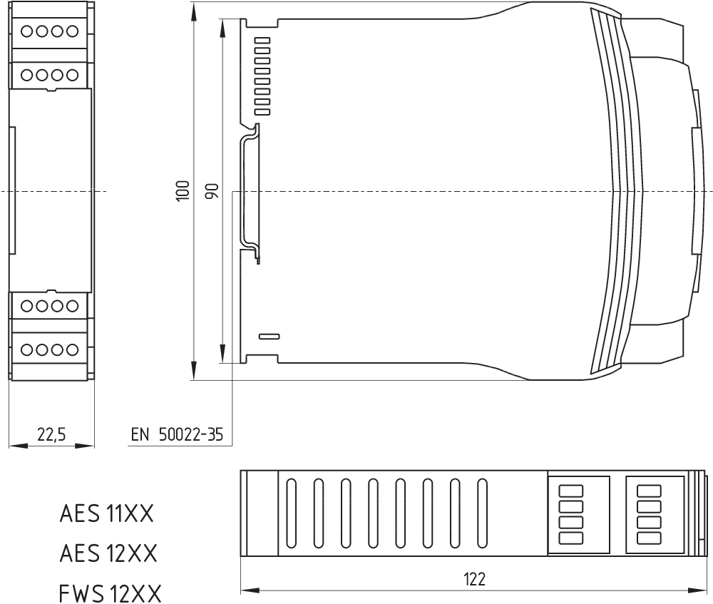
| Mounting |
EN 60715 e uygun standart DIN rayının üzerine kilitlenir |
Mechanical data - Connection technique
| Terminal designations |
IEC/EN 60947-1 |
| Termination |
Sabit ya da esnek Vida bağlantısı M20 x 1.5 |
| Cable section, minimum |
0,25 mm² |
| Cable section, maximum |
2,5 mm² |
| Tightening torque of Clips |
0,6 Nm |
Mechanical data - Dimensions
| Width |
22,5 mm |
| Height |
100 mm |
| Depth |
121 mm |
Ambient conditions
| Degree of protection of the enclosure |
IP40 |
| Degree of protection of the mounting space |
IP54 |
| Degree of protection of clips or terminals |
IP20 |
| Ambient temperature |
+0 ... +55 °C |
| Storage and transport temperature |
-25 ... +70 °C |
| Resistance to vibrations |
10...55 Hz, Genlik 0.35 mm, ± 15 % |
| Restistance to shock |
30 g / 11 ms |
Ambient conditions - Insulation values
| Rated impulse withstand voltage Uimp |
4 kV |
| Overvoltage category |
III |
| Degree of pollution |
2 |
Electrical data
| Frequency range |
50 Hz 60 Hz |
| Operating voltage |
24 VAC -15 % / +10 % |
| Ripple voltage |
10 % |
| Thermal test current |
6 A |
| Rated operating voltage |
24 VAC |
| Rated operating voltage |
24 VDC |
| Rated AC voltage for controls, 50 Hz, minimum |
20,4 VAC |
| Rated control voltage at AC 50 Hz, maximum |
26,4 VAC |
| Rated AC voltage for controls, 60 Hz, minimum |
20,4 VAC |
| Rated control voltage at AC 60 Hz, maximum |
26,4 VAC |
| Rated AC voltage for controls at DC minimum |
20,4 VDC |
| Rated control voltage at DC, maximum |
28,8 VDC |
| Electrical power consumption |
5 W |
| Contact resistance, maximum |
0,1 Ω |
| Note (Contact resistance) |
yeni durumda |
| Drop-out delay in case of power failure, typically |
80 ms |
| Drop-out delay in case of emergency, typically |
20 ms |
| Pull-in delay at automatic start, maximum, typically |
100 ms |
| Pull-in delay at RESET, typically |
20 ms |
| Material of the contacts, electrical |
Ag-Ni 10 ve 0.2 µm altın kaplama |
Electrical data - Safe relay outputs
| Voltage, Utilisation category AC-15 |
230 VAC |
| Current, Utilisation category AC-15 |
6 A |
| Voltage, Utilisation category DC-13 |
24 VDC |
| Current, Utilisation category DC-13 |
6 A |
| Switching capacity, minimum |
10 VDC |
| Switching capacity, minimum |
10 mA |
| Switching capacity, maximum |
250 VAC |
| Switching capacity, maximum |
8 A |
Electrical data - Digital inputs
| Input signal, HIGH Signal "1" |
10 … 30 VDC |
| Input signal, LOW Signal "0" |
0 … 2 VDC |
| Conduction resistance, maximum |
40 Ω |
Electrical data - Digital Output
| Voltage, Utilisation category DC-12 |
24 VDC |
| Current, Utilisation category DC-12 |
0,1 A |
Electrical data - Relay outputs (auxiliary contacts)
| Switching capacity, maximum |
24 VDC |
| Switching capacity, maximum |
2 A |
Electrical data - Electromagnetic compatibility (EMC)
| EMC rating |
EMC-Directive |
Integral system diagnosis (ISD)
| Note (ISD -Faults) |
Aşağıdaki hatalar emniyetli kontrol modülleri tarafından kaydedilmiştir ve ISD ile belirtilir. |
| Faults |
Emniyet rölesi devreye girmede veya devre dışı kalmada başarısız Kapı kontaktları kapatmada ve açmada başarısız Anahtar bağlantılarının çapraz bağlantısı veya kısa devre kontrolü Anahtar bağlantılarının kesintisi Emniyetli kontrol modülünün giriş devreleri veya röle kontrol devreleri üzerinde arıza |
Other data
| Note (applications) |
Güvenlik sensörü Koruma sistemi |
Note
| Note (General) |
Inductive loads (e.g. contactors, relays, etc.) are to be suppressed by means of a suitable circuit. |
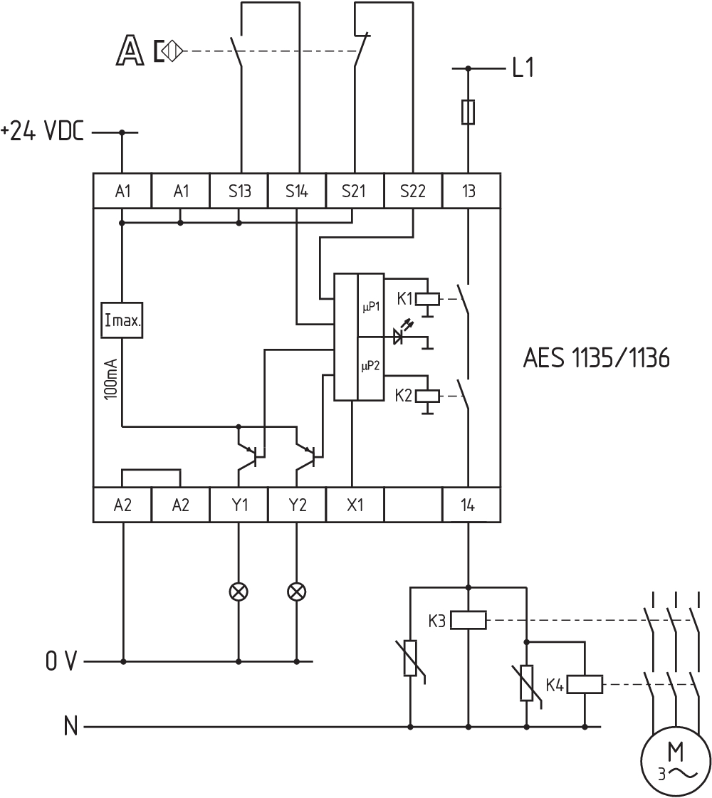
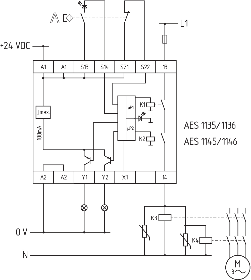
Wiring example
| Note (Wiring diagram) |
The wiring diagram is shown with guard doors closed and in de-energised condition. To secure a guard door up to PL d and Category 3 Monitoring 1 guard door(s), each with a magnetic safety sensor of the BNS range If one or two external relays or contactors are used to switch the load, the system can then only be classified in Category 3 to EN ISO 13849-1, if exclusion of the fault “Failure of the external contactors” can be substantiated and is documented, e.g. by using reliable down-rated contactors. A second contactor leads to an increase in the level of security by redundant switching to switch the load off. Modification for 2 NC contacts: The safety monitoring module can be modified to monitor two NC contacts by bridging the terminals A1 and X1. In this configuration, the short-circuit detection becomes inoperative. Expansion of enable delay time: The enable delay time can be increased from 0.1 s to 1.0 s by changing the position of a jumper link connection under the cover of the unit. The ISD tables (Intergral System Diagnostics) for analysis of the fault indications and their causes are shown in the appendix. |
Dil filtresi
Veri sayfası
Çalışma Talimatları ile Uygunluk beyanı
UL Sertifikası
Bilgi
Kablo döşeme örneği (elektr. kablolama)
SISTEMA-VDMA kütüphanesi
Adobe Reader’ın son sürümünü indirin
Ürün resmi (katalog özel fotoğraf)
Boyutsal resim temel bileşeni
Kablo döşeme örneği
Kablo döşeme örneği

103009970 SRB-E-201LC
- Plug-in screw terminals with coding
- STOP 0 Function
- 1 oder 2-channel control
- Start button / Auto-start
- 2 Safety outputs 2 A
- 1 Signalling output

103007672 SRB-E-301ST
- Plug-in screw terminals with coding
- STOP 0 Function
- 1 oder 2-channel control
- Start button / Auto-start
- 1 Auxiliary contact
- 3 safety contacts
Schmersal India Pvt. Ltd., Plot No - G-7/1, Ranjangaon MIDC, Tal. - Shirur, Dist.- Pune 412 220
Veriler ve ayrıntılar dikkatli bir şekilde kontrol edilmişlerdir. Görüntüler orijinalden farklı olabilir. Daha fazla teknik veri kılavuzda bulunabilir. Teknik değişiklikler ve hatalar olabilir.
Udarbejdet d. 26.02.2025 17:23