This document provides all the information you need for the mounting, set-up and commissioning to ensure the safe operation and disassembly of the switchgear. The operating instructions enclosed with the device must always be kept in a legible condition and accessible.
All operations described in the operating instructions manual must be carried out by trained specialist personnel, authorised by the plant operator only.
Please make sure that you have read and understood these operating instructions and that you know all applicable legislations regarding occupational safety and accident prevention prior to installation and putting the component into operation.
The machine builder must carefully select the harmonised standards to be complied with as well as other technical specifications for the selection, mounting and integration of the components.
The information contained in this operating instructions manual is provided without liability and is subject to technical modifications.
The Schmersal range of products is not intended for private consumers.
The products described in these operating instructions are developed to execute safety-related functions as part of an entire plant or machine. It is the responsibility of the manufacturer of a machine or plant to ensure the correct functionality of the entire machine or plant.
The safety switchgear must be exclusively used in accordance with the versions listed below or for the applications authorised by the manufacturer. Detailed information regarding the range of applications can be found in the chapter "Product description".
The user must observe the safety instructions in this operating instructions manual, the country specific installation standards as well as all prevailing safety regulations and accident prevention rules.
| Product type description: RSS 36 (1)-(2)-(3)-(4)-(5)-(6) |
| (1) | |
| without | Standard coding |
| I1 | Individual coding |
| I2 | Individual coding, multiple teaching |
| (2) | |
| without | Without diagnostic function (only on request 1)) |
| D | With diagnostic output |
| SD | With serial diagnostic function 2) |
| (3) | |
| without | Standard version without feedback circuit monitoring EDM (External Device Monitoring) |
| F0 | EDM with automatic reset 2) |
| F1 | EDM with manual reset 2) |
| (4) | |
| without | Without EMERGENCY STOP |
| Q | Acknowledge input error with EMERGENCY STOP 2) |
| (5) | |
| without | Without latching |
| R | With latching, latching force approx. 18 N |
| (6) | |
| ST | Connector plug M12, 8-pole |
| ST5 | Connector plug M12, 5-pole |
| (*) | |
| 1) | only for version -ST5 |
| 2) | only for version -ST |
For special versions, which are not listed in the ordering code, these specifications apply accordingly, provided that they correspond to the standard version.
This non-contact, electronic safety sensor is designed for application in safety circuits and is used for monitoring the position of movable safety guards. In this application, the safety sensor monitors the position of hinged, sliding or removable safety guards by means of the coded electronic actuator.
The safety function consists of safely switching off the safety outputs when the safety guard is opened and maintaining the safe switched off condition of the safety outputs for as long as the safety guard is open.
The safety switchgears are classified according to ISO 14119 as type 4 interlocking devices. Designs with individual coding are classified as highly coded.
Safety sensors and actuators with latching (ordering suffix 'R') always must be used in pairs. The latching force (approx. 18 N) exercised by the permanent magnet keeps hatches and small guards closed, also in a de-energised condition.
The system can be used as a door end stop up to 5 kg at 0.25 m/s.
With the F0/F1 option, the sensor performs the tasks of a safety-monitoring module. At both safety outputs, two auxiliary contactors1) or Relays1) (1) each with positive-action contacts in accordance with EN 60947-5-1 or EN 50205) can be connected, whose safety-related function is checked by the sensor by means of a feedback circuit (External Device Monitoring). The feedback circuit includes the series-wiring of the NC contacts of the auxiliary contactors or relays. For the F0 version, an "enabling switch" (without safety function) can be integrated into the feedback circuit. For the F1 version, a so-called "reset button" is required, which is monitored for a trailing edge. This function corresponds to the "manual reset function" to EN ISO 13849-1.
The Q option monitors simultaneous shutdown of the sensor inputs. Series-wired sensors enable integration of EMERGENCY STOP switching elements for applications to PLe. The EMERGENCY STOP contacts are supplied by the cross-circuit monitored output signals of an upstream electronic safety switchgear device. At the end of the chain, a sensor with Q option for connecting an acknowledgement function monitors the chain for synchronous shutdown of both channels. In the event of erroneous shutdown, the error must be rectified. The safety outputs can be reactivated only once the error has been acknowledged.
The diagnostic output of the safety sensor alternatively can be used as a conventional output or as a “serial output“ with input and output channel.
We shall accept no liability for damages and malfunctions resulting from defective mounting or failure to comply with the operating instructions manual. The manufacturer shall accept no liability for damages resulting from the use of unauthorised spare parts or accessories.
For safety reasons, invasive work on the device as well as arbitrary repairs, conversions and modifications to the device are strictly forbidden, the manufacturer shall accept no liability for damages resulting from such invasive work, arbitrary repairs, conversions and/or modifications to the device.
|
TÜV cULus ECOLAB FCC IC ANATEL |
| Normlar, talimatlar |
EN ISO 13849-1 EN IEC 60947-5-3 EN IEC 61508 |
| genel bilgiler |
Tek olarak kodlama, etkinleştirilmiş tekrarlanan öğreti |
| Coding level according to EN ISO 14119 |
Yüksek |
| Etkili kural |
RFID |
| Frequency band RFID |
125 kHz |
| Transmitter output RFID, maximum |
-6 dB/m |
| Gövdenin konstrüksiyon şekli |
Blok |
| Yerleştirme koşulları (mekanik) |
bir hizada değil |
| Sensör topolojisi |
Seri bağlantı için sensör |
| Gövdelerin malzemesi |
Plastik, fiber cam takviyeli termoplastik |
| Reaksiyon süresi, maksimum |
100 ms |
| Risk süresi, maximum |
200 ms |
| Aktüatörün reaksiyon süresi, maksimum |
100 ms |
| Girişlerin reaksiyon süresi, maksimum |
0,5 ms |
| Brüt ağırlık |
100 g |
| Mandallama |
Evet |
| Diyagnostik çıkış |
Evet |
| Kısa devre algılaması |
Evet |
| Kısa devre tanımı |
Evet |
| Seri bağlantı |
Evet |
| Güvenlik fonksiyonları |
Evet |
| Kaskat edilebilir |
Evet |
| Entegre gösterge, durum |
Evet |
| LED sayısı |
3 |
| Sinyalizasyon fonksiyolu yarı iletken çıktıların sayısı |
1 |
| Güvenli dijital çıkış sayısı |
2 |
| Normlar, talimatlar |
EN ISO 13849-1 EN IEC 61508 |
| Performance Level, up to |
e |
| Kontrol kategorisi EN ISO 13849 e göre |
4 |
| PFH değeri |
2,70 x 10⁻¹⁰ /h |
| PFD değeri |
2,10 x 10⁻⁵ |
| Safety Integrity Level (SIL) |
3 |
| Mission time |
20 Yıl(lar) |
| Uyarı düzlemleri |
yan taraf |
| Malzeme, etkili alan |
yan taraf |
| Mekanik ömür, minimum |
1.000.000 operasyon sayısı |
| Note (Mechanical life) |
Kumanda hızı < 0,25 m/s 5 kg kapı kütlelerinde devre aralığı |
| Güç, mandallama kuvveti, yaklaşık {N} |
18 N |
| Montaj |
A screw length of 25 mm is sufficient for sensor mounting and for side mounting of the actuators. 30 mm long screws are recommended when the actuator is mounted upright and/or when the sealing discs are used. |
| Type of the fixing screws |
2x M4 (cylinder head screws with washers DIN 125A / form A) |
| Tightening torque of the fixing screws, minimum |
2,2 Nm |
| Tightening torque of the fixing screws, maximum |
2,5 Nm |
| Switch distance, typical |
12 mm |
| Temin edilmiş anahtar mesafesi "ON" |
10 mm |
| Temin edilmiş anahtar mesafesi "OFF" |
20 mm |
| Note (switching distance) |
All switching distances in accordance EN IEC 60947-5-3 |
| Histeresis (anahtar mesafesi), maximum |
2 mm |
| Hassasiyet R' yi tekrarlayın |
0,5 mm |
| Not (Hassasiyet R' yi tekrarlayın R) |
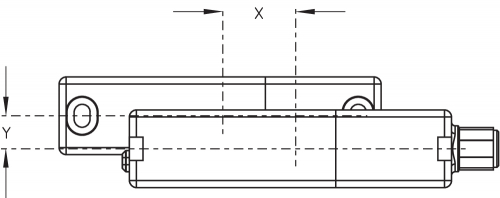
Eksenel dengeleme: Uzun taraf sensör ve uyarıcı için 8mm max yükseklik ayar sapmasına (x) izin verir (montaj toleransı veya koruma kapısının sarkması gibi durumlarda). Eksen sapması (y) maks. ± 18 mm'dir (bkz resim: çalışma prensibi).İki sensör sistemi arasındaki minimum boşluk 100 mm'dir. |
| Note (length of the sensor chain) |
Cable length and cross-section change the voltage drop dependiing on the output current |
| Note (series-wiring) |
Unlimited number of devices, oberserve external line fusing, max. 31 devices in case of serial diagnostic SD |
| Konektör, konektör |
Konektör M12, 8-kutup |
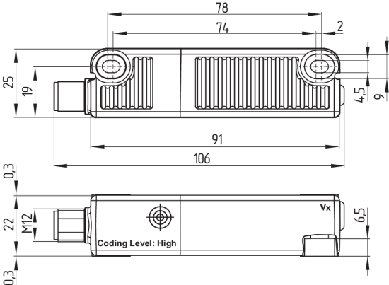
| Sensörün boyu |
22 mm |
| Sensörün genişliği |
106,3 mm |
| Sensörün yüksekliği |
25 mm |
| Koruma sınıfı |
IP65 IP67 IP69 |
| Ambient temperature |
-28 ... +70 °C |
| Storage and transport temperature |
-28 ... +85 °C |
| Göreli nem, maximum |
93 % |
| Note (Relative humidity) |
yoğuşmaz buzlanmaz |
| Titreşime karşı direnç EN 60068-2-6 göre |
10 … 55 Hz, Genlik 1 mm |
| şoka karşı direnç |
30 g / 11 ms |
| Protection class |
III |
| Permissible installation altitude above sea level, maximum |
2.000 m |
| Nominal izolasyon gerilimi |
32 VDC |
| Nominal darbeye dayanma gerilimi |
0,8 kV |
| Overvoltage category |
III |
| Kirlilik derecesi e göre IEC/EN 60664-1 |
3 |
| Operating voltage |
24 VDC -15 % / +10 % |
| Çalışma akımı, minimum |
0,5 mA |
| No-load supply current I0, typical |
35 mA |
| Rated operating voltage |
24 VDC |
| Çalışma akımı |
600 mA |
| N 60947-5-1 uyarınca koşullu nominal kısa devre akımı |
100 A |
| Hazır olma zamanı, maximum |
2.000 ms |
| Anahtarlama frekansı, maximum |
1 Hz |
| Utilisation category DC-12 |
24 VDC / 0,05 A |
| Elektriksel nominal sigorta değeri, maximum |
2 A |
| Designation, Safety inputs |
X1 and X2 |
| Current consumption of the safety inputs |
5 mA |
| Test pulse duration, maximum |
1 ms |
| Test pulse interval, minimum |
100 ms |
| Classification ZVEI CB24I, Sink |
C1 |
| Classification ZVEI CB24I, Source |
C1 C2 C3 |
| Designation, Safety outputs |
Y1 and Y2 |
| Çalışma akımı (emniyetli çıkışlar) |
250 mA |
| Çıkış akımı (güvenli çıkış), maksimum |
0,25 A |
| Emniyetli çıkış |
short-circuit proof, p-type |
| Voltage drop Ud, maximum |
1 V |
| Leakage current Ir, maximum |
0,5 mA |
| Voltage, Utilisation category DC-12 |
24 VDC |
| Current, Utilisation category DC-12 |
0,25 A |
| Voltage, Utilisation category DC-13 |
24 VDC |
| Current, Utilisation category DC-13 |
0,25 A |
| Test pulse interval, typical |
1000 ms |
| Test pulse duration, maximum |
0,3 ms |
| Classification ZVEI CB24I, Source |
C2 |
| Classification ZVEI CB24I, Sink |
C1 C2 |
| Designation, Diagnostic outputs |
OUT |
| Design of control elements |
short-circuit proof, p-type |
| Voltage drop Ud, maximum |
2 V |
| Voltage, Utilisation category DC-12 |
24 VDC |
| Current, Utilisation category DC-12 |
0,05 A |
| Voltage, Utilisation category DC-13 |
24 VDC |
| Current, Utilisation category DC-13 |
0,05 A |
| Interfering radiation |
IEC 61000-6-4 |
| Not (LED anahtarlama koşulları göstergesi) |
Sari LED: anahtarlama koşulu Yeşil LED : Besleme gerilimi kırmızı LED : hata |
| PIN 1 |
1A1 Ue: (1) |
| PIN 2 |
X1 Emniyetli giriş 1 |
| PIN 3 |
A2 GND Mavi |
| PIN 4 |
Y1 Emniyetli çıkış 1 Siyah |
| PIN 5 |
OUT Diyagnostik çıkış OUT Gri |
| PIN 6 |
X2 Emniyetli giriş 2 mor |
| PIN 7 |
Y2 Emniyetli çıkış 2 kırmızı |
| PIN 8 |
IN fonksiyonsuz Pembe |
FCC/IC - Note
This device complies with Part 15 of the FCC Rules and contains licence-exempt transmitter/receivers that are compliant with ISED (Innovation, Science and Economic Development) Canada licence-exempt RSS standard(s).
Operation is subject to the following two conditions:
(1) This device may not cause harmful interference signals, and
(2) This device must be able to tolerate interference signals. These also include interference signals that could cause the device to function improperly.
This device complies with the nerve stimulation limits (ISED SPR-002) when operated at a minimum distance of 100 mm. Changes or modifications not expressly approved by K.A. Schmersal GmbH & Co. KG could void the user's authority to operate the equipment.
The licence-free transmitter/receiver contained in this device satisfies the requirements of the "Radio Standards Specification" of the Innovation, Science and Economic Development Canada (ISED) authority that apply to licence-free radio equipment. Operation is permissible under the following two conditions:
(1) The device must not create disturbances.
(2) The device must tolerate received radio frequency interference, even if this could impair its functionality.
This device complies with the nerve stimulation limits (ISED CNR-102) when operated at a minimum distance of 100 mm.
In the event of changes or modifications that have not been expressly approved by K.A. Schmersal GmbH & Co. KG, the user's authorisation to use the device may become ineffective.
| 20941-22-14519 | Este equipamento nao tem direito àprotecao contra interferência prejudicial e nao pode causar interferencia em sistemas devidamente autorizados. Para maiores informacores consultar: www.gov.br/anatel |
Ensure the safety sensor and actuator is mounted on a flat surface. The component can be mounted in any position. The universal mounting holes provide for a variable mounting by means of M4 screws. Mounting: a screw length of 25 mm is sufficient for sensor mounting and for side mounting of the actuators. 30 mm long screws are recommended when the actuator is mounted upright and/or when the sealing discs are used. (Tightening torque 2,2...2,5 Nm). The labelled surfaces of the safety sensor and the actuator have to be opposite. The safety sensor must only be used within the assured switching distances ≤ sao and ≥ sar.
To avoid any interference inherent to this kind of system and any reduction of the switching distances, please observe the following guidelines:
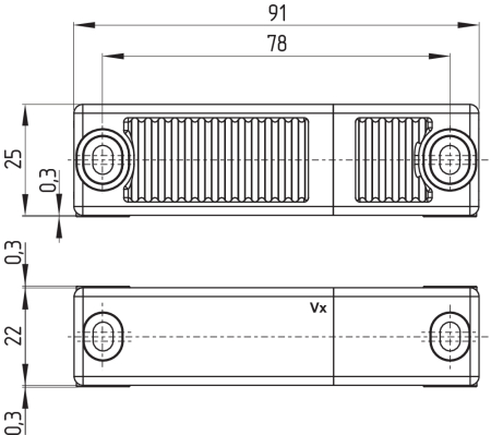
All measurements in mm.
Safety sensor
Actuator
Set of disposable screws (order separately)
- 4x M4x25 incl. washers, order number 101217746
- 4x M4x30 incl. washers, Bestellnummer 101217747
Sealing kit (order separately)
- Order number 101215048
- 8 plugs and 4 under seals
- To seal the mounting holes and as a spacer (approx. 3 mm) to facilitate cleaning below the mounting surface
- Also suitable as tamper protection for the screw attachment
| Switching distances in mm to IEC 60947-5-3 | |
|---|---|
| Typical switching distance styp: | 12 |
| Assured switching distance sao: | 10 |
| Assured switch-off distance sar: | 20 |
| Switching distances in mm to IEC 60947-5-3 | Actuator RST | Actuator RST as of V2 | |
|---|---|---|---|
| Sensor RSS | styp | 12 | 12 |
| sao | 10 | 8 | |
| sar | 16 | 16 | |
| Sensor RSS as of V2 | styp | 12 | 12 |
| sao | 10 | 10 | |
| sar | 20 | 20 | |
The side allows for a maximum height misalignment (X) of sensor and actuator of ± 8 mm (e.g. mounting tolerance or due to guard door sagging). The axial misalignment (y) is max. ± 18 mm.
Actuating curves
The actuating curves represent the typical switching distance of the safety sensor during the approach of the actuator subject to the actuating direction
| Transverse misalignment | Height misalignment |
|---|---|
 | 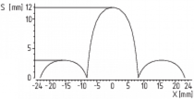 |
The continuous signal of the yellow LED signals the actuator detection; the flashing of the yellow LED signals that the safety sensor is actuated in the hysteresis area.
The correct functionality of both safety channels must be checked by means of the connected safety-monitoring module.
The safety outputs can be integrated into the safety circuit of the control system. For applications of PL e / category 4 to EN ISO 13849-1, the safety outputs of the safety sensor or of the sensor chain must be wired to a safety monitoring-module of the same category.
The required electrical cable fuse protection must be integrated in the installation.
Protection is not required when pilot wires are laid. The cables however must be separated from the supply and energy cables. The max. fuse rate for a sensor chain depends on the section of the connecting cable of the sensor.
Requirements for the connected safety-monitoring module:
dual-channel safety input, suitable for p-type sensors with NO function
As an alternative to an evaluation unit, the safety sensors of the RSS 36..F0 resp. RSS 36...F1 series can also be used for direct control and monitoring of safety contactors as first sensor of a series-wired chain.
The sensors cyclically switch off the safety output to test them. The safety-monitoring module therefore does not need to be equipped with a cross-wire short detection. The switch-off times must be tolerated by the safety-monitoring module. The switch -off time of the safety sensor is additionally extended depending on the cable length and the capacity of the cable used. Typically, a switch-off time of 250 μs is reached with a 30-m connecting cable.
Cable design
The wiring capacitance of the connecting cable of the safety sensor must not exceed 50 nF.
Depending on the strand structure, normal unshielded 200 m long control cables LIYY 0.25 mm² to 1.5 mm² have a wiring capacitance of approx. 20 … 50 nF
Series-wiring can be set up. In the case of a series connection, the risk time remains unchanged and the reaction time increases by the sum of the reaction time of the inputs per additional unit specified in the technical data. The number of components is only limited by the external cable protection according to the technical data and the line loss. Series-wiring of up to 31 RSS 36 … SD components with serial diagnostics is possible.
The application examples shown are suggestions. They however do not release the user from carefully checking whether the switchgear and its set-up are suitable for the individual application. The application examples shown are suggestions.
Wiring example 1: Series-wiring of the RSS 36 with conventional diagnostic output
The voltage is supplied to both safety inputs of the last safety sensor of the chain (considered from the safety-monitoring module).
The safety outputs of the first safety sensor are wired to the safety-monitoring module. The diagnostic output can be connected for instance to a PLC.
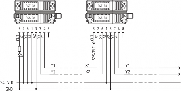
Y1 and Y2 = Safety outputs → Safety monitoring module
Wiring example 2: series-wiring of the RSS 36 with serial diagnostic function
In devices with the serial diagnostics function (ordering suffix -SD), the serial diagnostics connections are wired in series and connected to a SD-Gateway for evaluation purposes. The voltage is supplied to both safety inputs of the last safety sensor of the chain (considered from the safety-monitoring module).
The safety outputs of the first safety sensor are wired to the safety-monitoring module. The serial Diagnostic Gateway is connected to the serial diagnostic input of the first safety sensor.

Y1 and Y2 = Safety outputs → Safety monitoring module
SD-IN → Gateway → Field bus
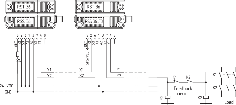
Wiring example 3: Series-wiring with RSS 36…F0
The safety sensor RSS 36 ...F0 directly controls positive-action auxiliary contactors or relays. The monitoring of the external contactors or relays is enabled by the feedback circuit, which is built by the NC contacts of K1, K2. As no further button is used, the auxiliary contactors or relays are immediately enabled when the safety guard is closed. This kind of automatic reset is permissible only if a hazard from the machine starting up can be ruled out.
The feedback circuit can be extended by an enabling button. The sensor is switched on, as soon as the enabling button is pushed. The design then corresponds analogously to the wiring examples of the F1 variants The internal safety-monitoring module of variant F0 is not equipped with an edge detection for the button. If required, a "manual reset" to EN ISO 13849-1 must be realised by other components of a local control system.
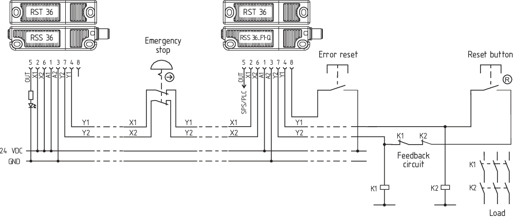
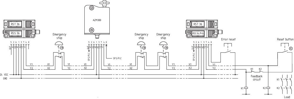
Wiring example 4: Series-wiring with RSS 36…F1-Q as master with EDM
The safety sensor RSS 36...F1 directly controls positive-action auxiliary contactors or relays. The F1 function also monitors a trailing edge of the reset button in addition to the feedback contacts. The sensor switches on when the button is released. It can be used for manual reset on safety guards, which can be stepped over. The protected area must be designed so that a single reset button suffices. The Q function monitors EMERGENCY STOP buttons integrated into the chain and requires a separate error acknowledgement button.
Wiring example 5: Series-wiring with RSS260…SD-F1-Q as master with EDM and serial diagnostics
The safety sensor RSS 260...F1 directly controls positive-action auxiliary contactors or relays. The F1 function also monitors a trailing edge of the reset button in addition to the feedback contacts. The sensor switches on when the button is released. It can be used for manual reset on safety guards, which can be stepped over. The protected area must be designed so that a single reset button suffices. The Q function monitors the EMERGENCY STOP buttons integrated into the chain. In the event of erroneous EMERGENCY STOP signals, the error message must be reset via the serial diagnostic channel using Q monitoring
Wiring example 5: Series-wiring with RSS 36…F1-Q with mixed components
The safety sensor RSS 36...F1 directly controls positive-action auxiliary contactors or relays. The F1 function also monitors a trailing edge of the reset button in addition to the feedback contacts. The sensor switches on when the button is released. It can be used for manual reset on safety guards, which can be stepped over. The protected area must be designed so that a single reset button suffices. The Q function monitors EMERGENCY STOP buttons integrated into the chain and requires a separate error acknowledgement button.
| Function safety switchgear | Pin configuration of the connector | Colour codes of the Schmersal connectors | Poss. colour codes of other customary connectors | |||||
|---|---|---|---|---|---|---|---|---|
| 8-pin version ST | 5-pin version ST | 8-pin version ST | 5-pin version ST | to IEC 60947-5-2: 2007 | ||||
| with conventional diagnostic outpu | with serial diagnostic function |  |  | IP67 / IP69 (PUR) | IP69 (PVC) | IP67 / IP69 (PUR) | ||
| A1 | Ue | 1 | 1 | WH | BN | BN | BN | |
| X1 | Safety input 1 | 2 | BN | WH | WH | |||
| A2 | GND | 3 | 3 | GN | BU | BU | BU | |
| Y1 | Safety output 1 | 4 | 4 | YE | BK | BK | BK | |
| OUT | Diagnoseausgang | SD-output | 5 | 5 | GY | GY | GY | GY |
| X2 | Safety input 2 | 6 | PK | VT | PK | |||
| Y2 | Safety output 2 | 7 | 2 | BU | RD | WH | VT | |
| IN | without function | SD-input | 8 | RD | PK | OR | ||
| Connecting cables with coupling (female) IP67 / IP69, M12, 8-pole - 8 x 0.25 mm² to DIN 47100 | |
|---|---|
| Cable length | Ordering code |
| 2,5 m | 103011415 |
| 5,0 m | 103007358 |
| 10,0 m | 103007359 |
| 15,0 m | 103011414 |
| Connecting cables (PVC) with socket (female) M12, 8-pole - 8 x 0.21 mm², IP69 | |
|---|---|
| Cable length | Ordering code |
| 5.0 m | 101210560 |
| 5.0 m, angled | 101210561 |
| 10.0 m | 103001389 |
| 15.0 m | 103014823 |
| Connecting cables (PUR) with coupling (female) IP67 / IP69, M12, 5-pole - 5 x 0.34 mm² to EN 60947-5-2 | |
|---|---|
| Cable length | Ordering code |
| 5.0 m | 103010816 |
| 10.0 m | 103010818 |
| 15.0 m | 103010820 |
Protection is not required when pilot wires are laid. The cables however must be separated from the supply and energy cables. The required electrical cable fuse protection must be integrated in the installation. The max. fuse rate for a sensor chain depends on the section of the connecting cable of the sensor.
Safety sensors with standard coding are ready to use upon delivery.
Individually coded safety sensors and actuators will require the following "teach-in" procedure:
For ordering suffix -I1, the executed allocation of safety switchgear and actuator is irreversible.
For ordering suffix -I2, the "teach-in" procedure for a new actuator can be repeated an unlimited number of times. When a new actuator is taught, the code, which was applicable until that moment, becomes invalid. Subsequent to that, an enabling inhibit will be active for ten minutes, thus providing for an increased protection against tampering. The green LED will flash until the expiration of the time of the enabling inhibit and the detection of the new actuator. In case of power failure during the lapse of time, the 10-minutes tampering protection time will restart.
The safety outputs can be integrated into the safety circuit of the control system.
The opening of a safety guard, i.e. the actuator is removed out of the active zone of the sensor, will immediately disable the safety outputs of the sensor.
The safety sensor indicates the operating condition and faults by means of three-colour LEDs located in the lateral surfaces of the sensor.
The green LED indicates that the safety sensor is ready for operation. The supply voltage is on and all safety inputs are present.
Flashing (1Hz) of the green LED signals that a voltage is missing on one or both of the safety inputs (X1 and/or X2).
The yellow LED always signals the presence of an actuator within range. If the actuator is operating in the limit area of the sensor switching distance, it will be indicated by flashing.
The flashing can be used to prematurely detect variations in the clearance between the sensor and the actuator (e.g. sagging of a safety guard). The sensor must be adjusted before the distance to the actuator increases and before the safety outputs are disabled, thus stopping the machine. If an error is detected, the red LED will be activated.
| LED indication (red) | Error cause | |
|---|---|---|
| 1 flash pulse |  | Error output Y1 |
| 2 flash pulses |  | Error output Y2 |
| 3 flash pulses |  | Cross-wire Y1/Y2 |
| 4 flash pulses |  | Ambient temperature too high |
| 5 flash pulses |  | Incorrect or defective actuator |
| 6 flash pulses |  | Discrepancy time error at X1/X2 |
| Continuous red (yellow LED flashing) |  | Actuator teaching (if actuator within range) |
| Continuous red (possibly with yellow flashing LED) | | Internal fault, with yellow flashing teaching procedure |
A diagnostic output additionally indicates the switching condition of the safety switchgear. These signals can be used in a downstream control.
The short-circuit proof diagnostic output OUT can be used for central visualisation or control tasks, e.g. in a PLC.
The diagnostic output is not a safety-related output.
Error
Errors which no longer guarantee the function of the safety switchgear (internal errors) cause the safety outputs to be disabled within the duration of risk. After fault rectification, the error message is reset by opening and re-closing the corresponding safety guard.
Error warning
A fault that does not immediately endanger the safety function of the safety switchgear (e.g. too high ambient temperature, safety output at external potential, cross-circuit) leads to delayed shutdown. This signal combination, diagnostic output disabled and safety channels still enabled, can be used to stop the production process in a controlled manner.
An error warning is deleted when the cause of error is eliminated.
If the fault warning remains on for 30 minutes, the safety outputs are also switched off (red LED flashes).
| Table 1: Examples of the diagnostic function of the safety-sensor with conventional diagnostic output | |||||||
|---|---|---|---|---|---|---|---|
| Sensor function | LED's | Diagnostic- output | Safety outputs | Comments | |||
| green | red | yellow | Y1, Y2 | ||||
| I. | Supply voltage | On | Off | Off | 0 V | 0 V | Voltage on, no evaluation of the voltage quality |
| II. | Actuated | Off | Off | On | 24 V | 24 V | The yellow LED always signals the presence of an actuator within range. |
| III. | Actuated, actuator in limit area | Off | Off | Flashes (1Hz) | 24 V pulsed | 24 V | The sensor must be adjusted before the distance to the actuator increases and before the safety outputs are disabled, thus stopping the machine. |
| IV. | Internal error or in the event of simultaneous flashing, teach-in process | On | Off | Flashes (1Hz) | 24 V | 0 V | The sensor awaits a signal on the feedback circuit: F0: Closure of the feedback circuit F1: Falling edge on the feedback circuit |
| V. | Actuated in limit area and feedback circuit open | On | Off | flashes alternating (1Hz / 5Hz) | 24 V pulsed | 0 V | LED indication combines the sensor functions III. and IV. |
| VI. | Error warning, sensor actuated | Off | Flashes | Off | 0 V | 24 V | After 30 minutes if the error is not rectified |
| VII. | Error | Off | flashes / on | off / flashes | 0 V | 0 V | Refer to table with flash codes |
| VIII. | Teach actuator | Off | On | Flashes | 0 V | 0 V | Sensor in teaching mode |
| IX. | Protection time | Flashes | Off | Off | 0 V | 0 V | 10 minutes pause after re-teaching |
| X. | No input signal at X1 and/or X2 | Flashes (1Hz) | Off | Off | 0 V | 0 V | Example: door open; a door in the safety circuit upstream is also open. |
| XI. | No input signal at X1 and/or X2 | Flashes (1Hz) | Off | On | 24 V | 0 V | Example: door closed, a door in the safety circuit upstream is open. |
Safety sensors with serial diagnostic cable have a serial input and output instead of the conventional diagnostic output. If RSS / CSS safety sensors are wired in series, the safety channels as well as the inputs and outputs of the diagnostic channels are wired in series.
Up to 31 safety switchgear devices can be connected in series with serial diagnostics. For the evaluation of the serial diagnostics line either the PROFIBUS-Gateway SD-I-DP-V0-2 or the Universal-Gateway SD-I-U-… are used. This SD-Gateway is integrated as a slave in an existing field bus system. In this way, the diagnostic signals can be evaluated by means of a PLC. The necessary software for the integration of the SD-Gateway is available for download at products.schmersal.com.
The response data and the diagnostic data are automatically and permanently written in the assigned input byte of the PLC for each safety sensor in the series-wired chain.
The request data for each safety sensor are transmitted to the device through an output byte of the PLC.
In the event of a communication error between the SD-Gateway and the safety sensor, the switching condition of the safety output of the safety sensor is maintained.
Bit 0: safety outputs enabled
Bit 1: safety sensor actuated, actuator identified
Bit 3: feedback circuit open or reset button not actuated
Bit 4: both safety inputs live
Bit 5: safety sensor actuated in hysteresis area
Bit 6: error warning, switch-off delay activated
Bit 7: error, safety outputs switched off
Error
Errors which no longer guarantee the function of the safety switchgear (internal errors) cause the safety outputs to be disabled within the duration of risk. The fault is reset, when the cause is eliminated and bit 7 of the request byte changes from 1 to 0 or the safety guard is opened. Faults at the safety outputs are only deleted upon the next release, as the fault rectification cannot be detected sooner.
Error warning
A fault that does not immediately endanger the safety function of the safety switchgear (e.g. too high ambient temperature, safety output at external potential, cross-circuit) leads to delayed shutdown. This signal combination, diagnostic output disabled and safety channels still enabled, can be used to stop the production process in a controlled manner.
An error warning is deleted when the cause of error is eliminated.
If the fault warning remains on for 30 minutes, the safety outputs are also switched off (red LED flashes).
Diagnostic error (warning)
If an error (warning) is signalled in the response byte, detailed fault information can be read out.
| Table 2: Function of the visual diagnostic LEDs, the serial status signals and the safety outputs by means of an example | ||||||||||||
|---|---|---|---|---|---|---|---|---|---|---|---|---|
| System condition | LED's | Safety outputs | Status signals serial diagnostic byte Bit n° | |||||||||
| green | red | yellow | Y1, Y2 | 7 | 6 | 5 | 4 | 3 | 2 | 1 | 0 | |
| Non-actauted, inputs X1 and X2 enabled | On | Off | Off | 0 V | 0 | 0 | 0 | 1 | 0 | 0 | 0 | 0 |
| Actuated, feedback circuit open / not actuated | On | Off | Flashes (5Hz) | 0 V | 0 | 0 | 0 | 1 | 1 | 0 | 1 | 0 |
| Actuated, safety outputs enabled | Off | Off | On | 24 V | 0 | 0 | 0 | 1 | 0 | 0 | 1 | 1 |
| Actuated in limit area | Off | Off | Flashes (1Hz) | 24 V | 0 | 0 | 1 | 1 | 0 | 0 | 1 | 1 |
| Actuated, warning | Off | On/flashes | Off | 24 V | 0 | 1 | 0 | 1 | 0 | 0 | 1 | 1 |
| Actuated, fault | Off | On/flashes | Off | 0 V | 1 | 1 | 0 | 1 | 0 | 0 | 1 | 0 |
The shown bit order of the diagnostic byte is an example. A different combination of the operational conditions will lead to a change of the bit order. | ||||||||||||
| Table 3: Tabular overview of status signals, warnings or error messages (The described condition is reached, when Bit = 1) | ||||
|---|---|---|---|---|
| Communication directions: | Request byte: | from the PLC to the local safety sensor | ||
| Response byte: | from the local safety sensor to the PLC | |||
| Warning/error byte: | from the local safety sensor to the PLC | |||
| Bit n° | Request byte | Response byte | Diagnostic | |
| Error warning | Error messages | |||
| Bit 0: | --- | Safety output activated | Error output Y1 | Error output Y1 |
| Bit 1: | --- | Actuator detected | Error output Y2 | Error output Y2 |
| Bit 2: | --- | --- | Cross-wire Y1/Y2 | Cross-wire Y1/Y2 |
| Bit 3: | --- | --- | Temperature too high | Temperature too high |
| Bit 4: | --- | Input condition X1 and X2 | --- | Incorrect or defective actuator |
| Bit 5: | --- | Actuated in limit area | Internal device error | Internal device error |
| Bit 6: | Error acknowledgement, Discrepancy time exceeded | Error warning | Communication error between the field bus Gateway and the safety switchgear | Error, discrepancy time exceeded at X1/X2 |
| Bit 7: | Error reset | Error (enabling path switched off) | --- | --- |
The safety function of the safety components must be tested. The following conditions must be previously checked and met:
| Functional test after assembly and connection of the RSS 36…-F0/-F1 All safety guards must be closed prior to the start of the functional test. The feedback circuit must be opened. 1) | |||
|---|---|---|---|
| No. | Action to test the operation | Reaction RSS 36 F0 version | Reaction RSS 36 F1 version |
| 1 | Switch on the operating voltage | The yellow LED flashes at 5 Hz and the relays are disabled. | The yellow LED flashes at 5 Hz and the relays are disabled. |
| 2 | Close the feedback circuit: actuate the connected button 2) | The yellow LED is on and both connected relays are enabled | No change compared to 1 |
| 3 | Only version F1: reset button actuation | No change compared to 2 | The yellow LED is on and both connected relays are enabled |
| 1) If no button is used, the feedback circuit must be opened by loosening the cable. To that effect, the voltage must be switched off. 2) If no button is used, the feedback circuit must be closed by reconnecting the cable. To that effect, the voltage must be switched off. | |||
With the F1 function, the button monitored on the falling edge must be actuated.
A non-monitored button integrated into the feedback circuit with function F0 is effective on closing.
An emergency-stop switching element integrated into series wiring can be monitored by the Q function in the last sensor of the chain. This monitors the simultaneous shutdown of its safety inputs and closes the safety outputs in the event of deviations greater than 500 ms. A malfunction in the chain detected in this way must be rectified immediately. Release is only then possible after the error has been acknowledged. The error will remain saved even in the event of a power interruption. Error acknowledgement must be effected via the negative edge of an acknowledge button connected to pin 8 or via the serial diagnosis line.
In addition, when emergency-stop switching elements are integrated, a reset button must be provided, as no automatic restart of the machine is permissible when an emergency-stop command is revoked.
As per the test interval referenced in the Maintenance chapter, the emergency-stop switching elements monitored in this way meet the requirements to PL e.
In the case of correct installation and adequate use, the safety switchgear features maintenance-free functionality. A regular visual inspection and functional test, including the following steps, is recommended:
The safety switchgear must be disassembled in a de-energised condition only.