This document provides all the information you need for the mounting, set-up and commissioning to ensure the safe operation and disassembly of the switchgear. The operating instructions enclosed with the device must always be kept in a legible condition and accessible.
All operations described in the operating instructions manual must be carried out by trained specialist personnel, authorised by the plant operator only.
Please make sure that you have read and understood these operating instructions and that you know all applicable legislations regarding occupational safety and accident prevention prior to installation and putting the component into operation.
The machine builder must carefully select the harmonised standards to be complied with as well as other technical specifications for the selection, mounting and integration of the components.
The information contained in this operating instructions manual is provided without liability and is subject to technical modifications.
The Schmersal range of products is not intended for private consumers.
The products described in these operating instructions are developed to execute safety-related functions as part of an entire plant or machine. It is the responsibility of the manufacturer of a machine or plant to ensure the correct functionality of the entire machine or plant.
The safety switchgear must be exclusively used in accordance with the versions listed below or for the applications authorised by the manufacturer. Detailed information regarding the range of applications can be found in the chapter "Product description".
The user must observe the safety instructions in this operating instructions manual, the country specific installation standards as well as all prevailing safety regulations and accident prevention rules.
| Product type description: AZ 16-(1)ZV(2)K-(3)-(4)-(5) |
| (1) | |
| without | 1 NO contact/1 NC contact |
| 02 | 2 NC contact |
| 03 | 3 NC contact |
| 12 | 1 NO contact/2 NC contacts |
| (2) | |
| without | Ejection force |
| R | Latching force 30 N |
| (3) | |
| G24 | with LED (only available for version with one NO and one NC contact) |
| (4) | |
| M16 | cable entry M16 |
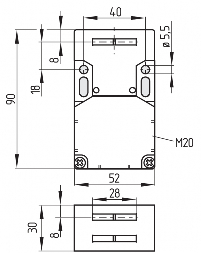
| M20 | Cable entry M20 |
| ST | Connector M12, 4 pole, bottom |
| STL | Connector M12, 4 pole, left |
| STR | Connector M12, 4 pole, right |
| (5) | |
| 2254 | Latching force 5 N |
| 1762 | Front mounting |
| 1637 | Gold-plated contacts |
For special versions, which are not listed in the ordering code, these specifications apply accordingly, provided that they correspond to the standard version.
The safety switches with separate actuator are suitable for sliding, hinged and removable safety guards, which need to be closed in order to ensure the necessary operational safety.
The safety switches are used for applications, in which the hazardous situation is terminated without delay when the safety guard is opened.
When the safety guard is opened, the NC contacts are positively opened and the NO contacts are closed.
We shall accept no liability for damages and malfunctions resulting from defective mounting or failure to comply with the operating instructions manual. The manufacturer shall accept no liability for damages resulting from the use of unauthorised spare parts or accessories.
For safety reasons, invasive work on the device as well as arbitrary repairs, conversions and modifications to the device are strictly forbidden, the manufacturer shall accept no liability for damages resulting from such invasive work, arbitrary repairs, conversions and/or modifications to the device.
| 证书 |
cULus CCC |
| 标准型 |
EN ISO 13849-1 EN ISO 14119 EN IEC 60947-5-1 |
| 编码等级,依据EN ISO 14119 |
低 |
| 工作原理 |
机电 |
| 外壳材料 |
塑料,玻璃纤维加固热塑塑料,自熄灭 |
| 毛重 |
120 g |
| 喷射力 |
是 |
| 操动方向数量 |
3 |
| 辅助触点数量 |
1 |
| 安全触点数量 |
1 |
| 电缆接头数量 |
3 |
| 标准型 |
EN ISO 13849-1 |
| 性能水平,最高 |
c |
| 类别 |
1 |
| B10D 常闭触点 (NC) |
2,000,000 操作 |
| 注意 |
按要求提供电气寿命。 |
| B10D 常开触点(NO) |
1,000,000 操作 |
| 注意 |
在10% Ie 及阻性负载时 |
| 任务时间 |
20 年 |
| 请注意: |
可用于允许排除单通道机构危险损坏的故障,并确保有足够的防操纵保护。 |
| 性能水平,最高 |
d |
| 类别 |
3 |
| 注意 |
用于双通道,并配有合适的逻辑单元。 |
| 任务时间 |
20 年 |
| 机械寿命,最少 |
1,000,000 操作 |
| 肯定断开行程 |
8 mm |
| 每个 NC 触点的正断开力, 最小力 |
10 N |
| 肯定断开操作力,最小 |
10 N |
| 操动速度,最大 |
2 m/s |
| 安装 |
螺钉 |
| 固定螺丝类型 |
2x M6 |
| 连接器位置 |
右侧 |
| 电缆入口 |
M12(A码) |
| 连接器 |
连接器插头M12,4芯,(A编码) |
| 传感器长度 |
30 mm |
| 传感器宽度 |
52 mm |
| 传感器高度 |
90 mm |
| 防护等级 |
IP67 |
| 工作环境温度 |
-30 ... +80 °C |
| 储存和运输温度 |
-40 ... +85 °C |
| 最大允许安装海拔高度 |
2,000 m |
| 额定绝缘电压 Ui |
500 V |
| 额定冲击耐受电压 Uimp |
6 kV |
| 过电压级别 |
III |
| 污染等级 |
3 |
| 额定冲击耐受电压,联接器 4针 {kV} |
2.5 kV |
| 热测试电流 |
10 A |
| 要求额定短路电流 |
1,000 A |
| 开关元件 |
1个NO 触点, 1个NC 触点 |
| 开关原理 |
缓动型,肯定断开常闭触点 |
| 开关频率 |
4,000 /h |
| 触点材料,电气 |
银 |
| 电压,应用类别 AC-15 |
230 VAC |
| 电流,应用类别 AC-15 |
4 A |
| 电压,应用类别 DC-13 |
24 VDC |
| 电流,应用类别 DC-13 |
4 A |
| 注,使用标准 DC-13 |
连接器 4芯 |
| 电压,应用类别 AC-15 |
230 VAC |
| 电流,应用类别 AC-15 |
4 A |
| 电压,应用类别 DC-13 |
24 VDC |
| 电流,应用类别 DC-13 |
4 A |
| 注,使用标准 DC-13 |
联接器 4-芯 |
Note about the safety classification
Basically suitable up to Cat. 1 / PL c.
With 2-channel usage with fault exclusion mechanism (if a fault exclusion to the 1-channel mechanics is authorised) and suitable logic applicable up to Cat. 3 / PL d

(Determined values can vary depending on the application-specific parameters hop, dop and tcycle as well as the load.)
If multiple safety components are wired in series, the Performance Level to EN ISO 13849-1 will be reduced due to the restricted error detection under certain circumstances.
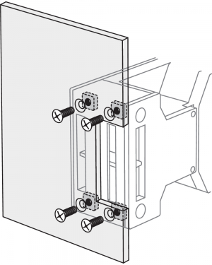
The mounting dimensions are indicated on the rear of the component. The enclosure must not be used as an end stop.
Any mounting position. The mounting position however must be chosen so that the ingress of dirt and soiling in the used opening is avoided. The unused openings must be sealed by means of slot sealing plugs (AZ 15/16 - 1476-1 available as accessory) after fitting.
See operating instructions Actuator.
| Actuating radii [mm] |  |  | ||
|---|---|---|---|---|
| over the small edge of the actuator | over the wide edge of the actuator | |||
| Rmin | d | Rmin | d | |
| AZ 15/16-B2 | - | - | 45 | 11 |
| AZ 15/16-B2-1747 | - | - | 45 | 11 |
| AZ 15/16-B3 | 32 | 11 | - | - |
| AZ 15/16-B3-1747 | 32 | 11 | - | - |
| AZ 15/16-B6 | 25 | 11 | 38 | 11 |
All measurements in mm.
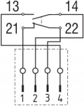
The contact labelling can be found in the wiring compartment of the switch. Appropriate cable glands with a suitable degree of protection are to be used.
Settle length x of the conductor: 6 mm
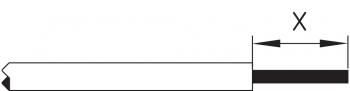
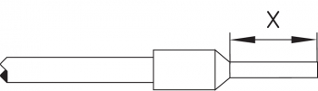
After wiring, dust and soiling must be removed from the wiring compartment. The safety switch is double insulated. The use of a protective ground connector therefore is not authorised.
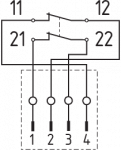
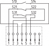
Contacts are shown with safety guard closed. All NC contacts have positive break B.
| AZ 16ZV.K | AZ 16-02ZV.K | AZ 16-12ZV.K |
|---|---|---|
 |  |  |
| AZ 16-03ZV.K | AZ 16ZV.K-ST | AZ 16-02ZV.K-ST |
|---|---|---|
 |  |  |
| AZ 16-12ZV.K-ST | LED | LED |
|---|---|---|
 | 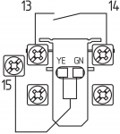 | 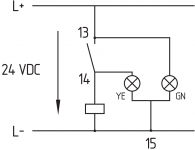 |
| Key | |
|---|---|
| B | Automatic opener, NC contact |
 | Normally-open contact |
 | Normally-closed contact |
The safety function of the safety components must be tested. In the case of correct installation and adequate use, the safety switchgear features maintenance-free functionality. A regular visual inspection and functional test, including the following steps, is recommended:
The safety switchgear must be disassembled in a de-energised condition only.