SRB400CS 24VDC
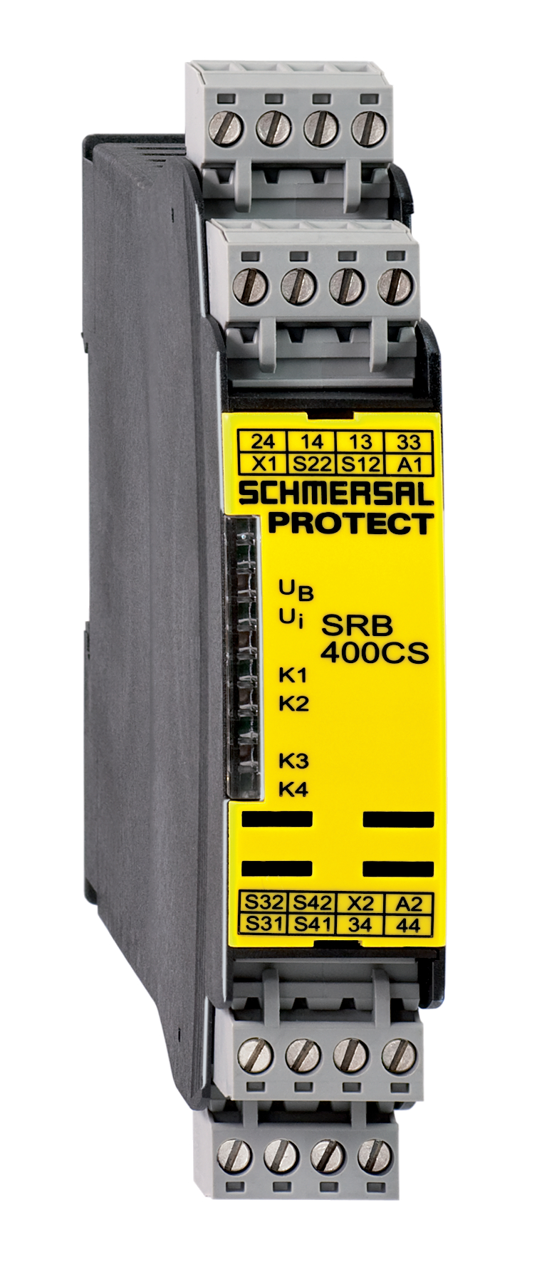
SRB400CS 24VDC
Downloads
- Level 1: Reset without edge detection, Optional Automatic reset function, Level 2: / Opener (NC) Opener (NC)
- Two-functions safety monitoring module (double evaluation)
- 2 x 2 enabling paths with different shut-down behaviour, e.g. emergency exit opens both enabling paths (level 1); guard door monitoring only opens the second enabling path (level 2)
- Suitable for signal processing of potential-free contacts, e.g. Emergency Stop command devices (level 1), position switches with safety function, solenoid interlocks and safety sensors (level 2)
Ordering data
| Replacement article number |
101177160 |
| Product type description |
SRB400CS 24VDC |
| Article number (order number) |
101176209 |
| EAN (European Article Number) |
4250116201938 |
| eCl@ss number, version 12.0 |
27-37-18-19 |
| eCl@ss number, version 11.0 |
27-37-18-19 |
| eCl@ss number, version 9.0 |
27-37-18-19 |
| ETIM number, version 7.0 |
EC001449 |
| ETIM number, version 6.0 |
EC001449 |
| Notice |
Auslaufprodukt |
Approvals - Standards
| Certificates |
cULus |
General data
| Standards |
EN IEC 62061 EN ISO 13849-1 EN IEC 60947-5-1 EN IEC 60947-5-3 EN IEC 60947-5-5 EN IEC 61508 EN IEC 60204-1 EN IEC 60947-1 |
| Climatic stress |
EN 60068-2-78 |
| Housing material |
Kunststoff, glasfaserverstärkter Thermoplast, belüftet |
| Gross weight |
235 g |
General data - Features
| Electronic Fuse |
Ja |
| Wire breakage detection |
Ja |
| Removable Terminals |
Ja |
| Start input |
Ja |
| Feedback circuit |
Ja |
| Automatic reset function |
Ja |
| Earth connection detection |
Ja |
| Integral system diagnostics, status |
Ja |
| Number of inputs for NC |
2 |
| Number of inputs for NO |
2 |
| Number of LEDs |
6 |
| Number of safety contacts |
4 |
| Safety classification |
| Vorschriften |
EN IEC 60947-5-1 EN IEC 61508 |
| Stop-Category |
0 |
| Safety classification - Relay outputs |
| Performance Level, stop 0, up to |
e |
| Category, Stop 0 |
4 |
| Diagnostic Coverage (DC) Level, Stop 0 |
≥ 99 % |
| PFH value, Stop 0 |
2,00 x 10⁻⁸ /h |
| Safety Integrity Level (SIL), Stop 0, suitable for applications in |
3 |
| Mission time |
20 Year(s) |
| Common Cause Failure (CCF), minimum |
65 |
Mechanical data
| Mechanical life, minimum |
10.000.000 Operations |
| Mounting |
Schnellbefestigung für Normschiene nach DIN EN 60715 |
Mechanical data - Connection technique
| Terminal designations |
IEC/EN 60947-1 |
| Termination |
starr oder flexibel Schraubanschluss M20 x 1.5 |
| Cable section, minimum |
0,25 mm² |
| Cable section, maximum |
2,5 mm² |
| Tightening torque of Clips |
0,6 Nm |
Mechanical data - Dimensions
| Width |
22,5 mm |
| Height |
100 mm |
| Depth |
121 mm |
Ambient conditions
| Degree of protection of the enclosure |
IP40 |
| Degree of protection of the mounting space |
IP54 |
| Degree of protection of clips or terminals |
IP20 |
| Ambient temperature |
-25 ... +45 °C |
| Storage and transport temperature |
-40 ... +85 °C |
| Resistance to vibrations |
10 ... 55 Hz, Amplitude 0,35 mm |
| Restistance to shock |
10 g / 11 ms |
Ambient conditions - Insulation values
| Rated impulse withstand voltage Uimp |
4 kV |
| Overvoltage category |
III |
| Degree of pollution |
2 |
Electrical data
| Operating voltage |
24 VDC -10 % / +20 % |
| Ripple voltage |
10 % |
| Rated operating voltage |
24 VDC |
| Rated AC voltage for controls at DC minimum |
20,4 VDC |
| Rated control voltage at DC, maximum |
28,8 VDC |
| Electrical power consumption |
4,4 W |
| Contact resistance, maximum |
0,1 Ω |
| Note (Contact resistance) |
in Neuzustand |
| Drop-out delay in case of power failure, typically |
80 ms |
| Drop-out delay in case of emergency, typically |
20 ms |
| Pull-in delay at automatic start, maximum, typically |
100 ms |
| ON delay at automatic start |
Einstellbar |
| Pull-in delay at RESET, typically |
20 ms |
| Material of the contacts, electrical |
Ag-Ni, selbstreinigend, zwangsgeführt |
Electrical data - Safe relay outputs
| Voltage, Utilisation category AC-15 |
250 VAC |
| Current, Utilisation category AC-15 |
6 A |
| Voltage, Utilisation category DC-13 |
24 VDC |
| Current, Utilisation category DC-13 |
6 A |
| Switching capacity, minimum |
10 VDC |
| Switching capacity, minimum |
10 mA |
| Switching capacity, maximum |
250 VAC |
| Switching capacity, maximum |
8 A |
Electrical data - Digital inputs
| Conduction resistance, maximum |
40 Ω |
Electrical data - Relay outputs (auxiliary contacts)
| Switching capacity, maximum |
24 VDC |
| Switching capacity, maximum |
2 A |
Electrical data - Electromagnetic compatibility (EMC)
| EMC rating |
EMV-Richtlinie |
Status indication
| Indicated operating states |
Stellung der Relais K2 Stellung der Relais K1 Interne Betriebsspannung Ui Stellung der Relais K3 |
Other data
| Note (applications) |
Sicherheits-Sensor Schutzeinrichtung NOT-HALT-Taster Seilzug-Notschalter |
Note
| Note (General) |
Induktive Verbraucher (Schütze, Relais etc.) sind durch eine geeignete Beschaltung zu entstören. |
| Note (Cross-circuit detection) |
Ebene 1 |
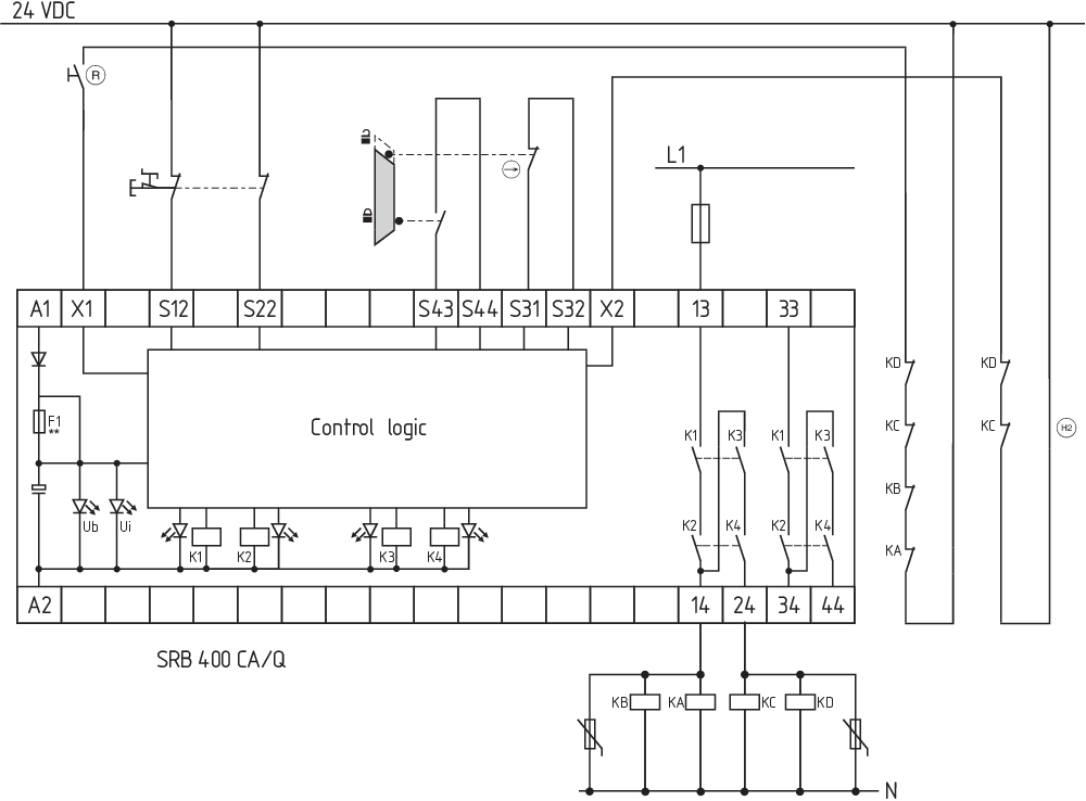
Wiring example
| Note (Wiring diagram) |
Das Schaltungsbeispiel ist bei geschlossenen Schutzeinrichtungen und im spannungslosen Zustand dargestellt. Leistungsebene: 2-kanalige Ansteuerung geeignet zur Kontaktverstärkung bzw. Kontaktvervielfältigung durch Schütze oder Relais mit zwangsgeführten Kontakten. Die Ansteuerung erkennt Querschlüsse, Drahtbrüche und Erdschlüsse im Überwachungskreis. Eingangsebene: 2-kanalige Ansteuerung, dargestellt am Beispiel einer NOT-HALT-Schaltung (Ebene 1) mit externem Reset-Taster (R), und einer Schutztürüberwachung (Ebene 2) mit Rückführkreis (H2). Automatischer Start (Ebene 1): Die Programmierung auf automatischen Start erfolgt durch die Einbindung des Rückführkreises an die Klemmen X1/+24VDC. Automatischer Start (Ebene 2): Die Programmierung auf automatischen Start erfolgt durch die Einbindung des Rückführkreises an die Klemmen X2/+24VDC. Bei nicht benötigtem Rückführkreis sind diese durch eine Brücke zu ersetzen. |
Sprachfilter
Datenblatt
Betriebsanleitung und Konformitätserklärung
UL-Zertifikat
Schaltungsbeispiel (elektr. Verdrahtung)
Download der aktuellen Version von Adobe Reader
Produktbild (Katalogeinzelphoto )
Schaltungsbeispiel
Schaltungsbeispiel
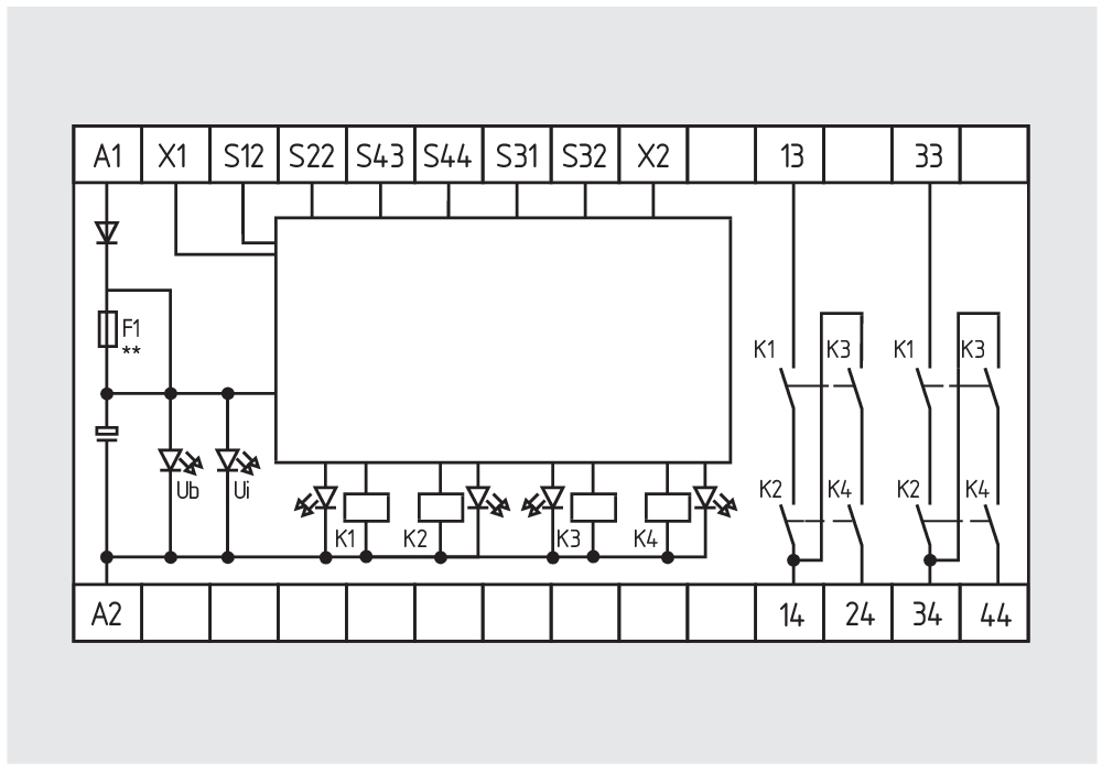
Symbol (technischer Standard)

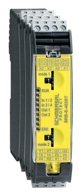
103007221 SRB-E-402ST
- Two-functions safety monitoring module (double evaluation), 2 x STOP 0
- 2 x 1 oder 2-channel control
- 2 x Start button / Auto-start
- 1 x Monitoring two-hand control panels to ISO 13851
- 2 safety contacts
- 2 Safety outputs
Schmersal India Pvt. Ltd., Plot No - G-7/1, Ranjangaon MIDC, Tal. - Shirur, Dist.- Pune 412 220
Die genannten Daten und Angaben wurden sorgfältig geprüft. Abbildungen können vom Original abweichen. Weitere technische Daten finden Sie in der Betriebsanleitung. Technische Änderungen und Irrtümer vorbehalten.
Generiert am: 21.05.2025, 14:41