EX-AZM300Z-I2-ST-1P2P-A-CR-3GD
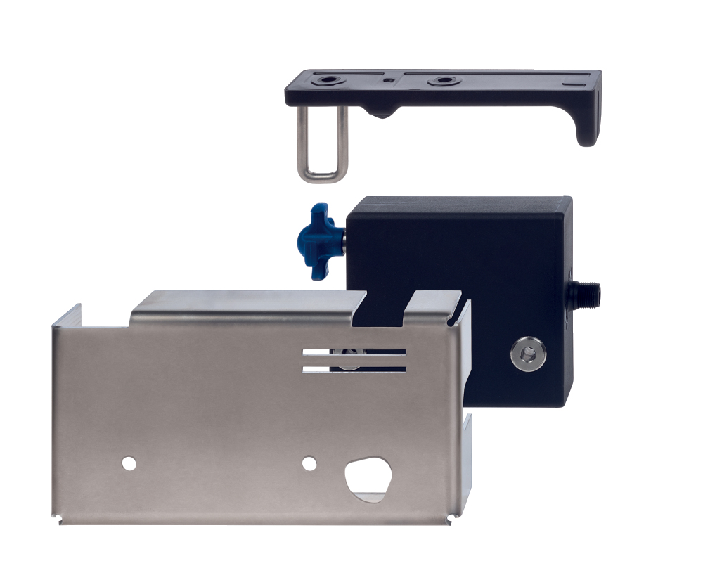
EX-AZM300Z-I2-ST-1P2P-A-CR-3GD
| Descripción del tipo de producto: EX-AZM300(1)(2)-ST(3)(4)(5) |
| (1) | |
| Z | Monitorización del bloqueo > |
| B | Monitorización del actuador |
| (2) | |
| sin | Codificación estándar |
| I1 | Codificación individual |
| I2 | Codificación individual, aprendizajes multiples |
| (3) | |
| 1P2P | 1 salida de diagnóstico, tipo P y 2 salidas de seguridad tipo P |
| SD2P | salida de diagnóstico en serie y 2 salidas de seguridad, tipo P |
| (4) | |
| sin | Principio de desbloqueo por tensión |
| A | Principio de bloqueo por tensión |
| (5) | |
| CL | Con caja de protección, bisagra de la puerta a la izquierda |
| CR | Con caja de protección, bisagra de la puerta a la derecha |
- Explosion protection for ATEX Zones 2 and 22
- RFID-technology for needs-based protection against tampering
- Thermoplastic enclosure
- Suitable for mounting to profile systems
- Suitable for hinged and sliding guards
- Series-wiring
- Manual release
Ordering data
| Product type description |
EX-AZM300Z-I2-ST-1P2P-A-CR-3GD |
| Article number (order number) |
103052212 |
| EAN (European Article Number) |
4030661632865 |
| eCl@ss number, version 12.0 |
27-27-26-03 |
| eCl@ss number, version 11.0 |
27-27-26-03 |
| eCl@ss number, version 9.0 |
27-27-26-03 |
| ETIM number, version 7.0 |
EC002593 |
| ETIM number, version 6.0 |
EC002593 |
Approvals - Standards
| Certificates |
ATEX (Konformitätserklärung) |
Explosion protection
| Explosion protection: regulations |
EN IEC 60079-0 EN 60079-7 EN 60079-31 |
| Explosion protection zones |
2 22 |
| Explosion protection category |
3G 3D |
| Explosion protection designation |
D II 3G Ex ic IIC T5 Gc X Ex tc IIIB T95°C Dc X |
General data
| Standards |
EN ISO 13849-1 EN ISO 14119 EN IEC 60947-5-3 EN IEC 61508 |
| Coding |
Codificación individual, aprendizajes multiples |
| Coding level according to EN ISO 14119 |
alta |
| Working principle |
RFID |
| Frequency band RFID |
125 kHz |
| Transmitter output RFID, maximum |
-6 dB/m |
| Housing material |
Plástico, termoplástico reforzado con fibra de vidrio, auto-extinguible |
| Duration of risk, maximum |
200 ms |
| Reaction time, switching off safety outputs via actuator, maximum |
100 ms |
| Reaction time, switching off safety outputs via safety inputs, maximum |
1,5 ms |
| Gross weight |
1.100 g |
General data - Features
| Power to lock |
Sí |
| Solenoid interlock monitored |
Sí |
| Latching |
Sí |
| Manual release |
Sí |
| Short circuit detection |
Sí |
| Cross-circuit detection |
Sí |
| Series-wiring |
Sí |
| Safety functions |
Sí |
| Integral system diagnostics, status |
Sí |
| Number of actuating directions |
1 |
| Number of fail-safe digital outputs |
2 |
| Safety classification |
| Vorschriften |
EN ISO 13849-1 EN IEC 61508 |
Safety classification - Interlocking function
| Performance Level, up to |
e |
| Category |
4 |
| PFH value |
5,20 x 10⁻¹⁰ /h |
| PFD value |
4,50 x 10⁻⁵ |
| Safety Integrity Level (SIL), suitable for applications in |
3 |
| Mission time |
20 Year(s) |
Safety classification - Guard locking function
| Performance Level, up to |
d |
| Category |
2 |
| PFH value |
2,00 x 10⁻⁹ /h |
| PFD value |
1,80 x 10⁻⁴ |
| Safety Integrity Level (SIL), suitable for applications in |
2 |
| Mission time |
20 Year(s) |
Mechanical data
| Mechanical life, minimum |
1.000.000 Operations |
| Note (Mechanical life) |
Si se utiliza como tope de resguardo: ≥ 50.000 maniobras (con pesos de resguardos ≤ 5 kg) y velocidad de accionamiento ≤ 0.5 m/s) |
| Angular misalignment between solenoid interlock and actuator, maximum |
2 ° |
| Energy impact (protective case), maximum |
7 J |
| Note (Energy impact) |
with stainless steel CL/CR protective enclosure |
| Holding force FZh in accordance with EN ISO 14119 |
1.150 N |
| Holding force Fmax, maximum |
1.500 N |
| Latching force, adjustable, position 1 |
25 N |
| Latching force, adjustable, position 2 |
50 N |
| Type of the fixing screws |
2x M6 |
| Note (Type of the fixing screws) |
Property class min. 8.8 |
| Tightening torque of the fixing screws, maximum |
8 Nm |
| Material of the fixing screws |
Acero inoxidable (V4A) |
Mechanical data - Switching distances according EN IEC 60947-5-3
| Switch distance, typical |
2 mm |
| Assured switching distance "ON" Sao |
1 mm |
| Assured switching distance "OFF" Sar |
20 mm |
Mechanical data - Connection technique
| Length of sensor chain, maximum |
200 m |
| Note (length of the sensor chain) |
Cable length and cross-section change the voltage drop dependiing on the output current |
| Note (series-wiring) |
Unlimited number of devices, oberserve external line fusing, max. 31 devices in case of serial diagnostic SD |
| Termination |
Conector M12, 8-polos, codificados A |
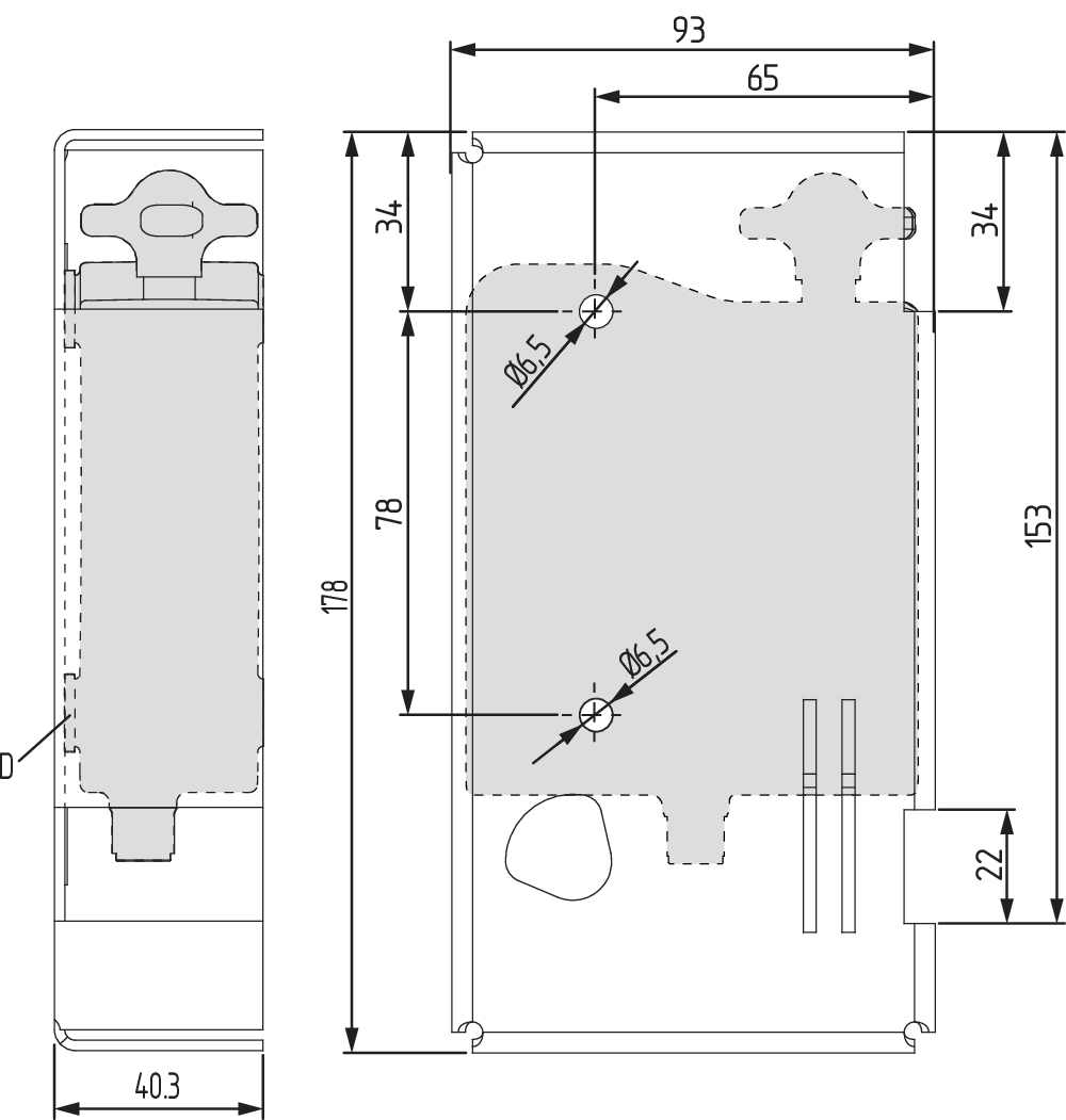
Mechanical data - Dimensions
| Length of sensor |
178 mm |
| Width of sensor |
93 mm |
| Height of sensor |
40,3 mm |
Ambient conditions
| Degree of protection |
IP66 IP67 IP69 |
| Ambient temperature |
+0 ... +50 °C |
| Storage and transport temperature |
-10 ... +90 °C |
| Relative humidity, maximum |
93 % |
| Note (Relative humidity) |
sin condensación sin escarcha |
| Resistance to vibrations |
10 … 150 Hz, amplitud 0,35 mm |
| Restistance to shock |
30 g / 11 ms |
| Protection class |
III |
| Permissible installation altitude above sea level, maximum |
2.000 m |
Ambient conditions - Insulation values
| Rated insulation voltage Ui |
32 VDC |
| Rated impulse withstand voltage Uimp |
0,8 kV |
| Overvoltage category |
III |
| Degree of pollution |
3 |
Electrical data
| Operating voltage |
24 VDC -15 % / +10 % |
| No-load supply current I0, typical |
100 mA |
| Current consumption with magnet ON, average |
200 mA |
| Current consumption with magnet ON, peak |
350 mA / 200 ms |
| Rated operating voltage |
24 VDC |
| Required rated short-circuit current |
100 A |
| External wire and device fuse rating |
2 A gG |
| Time to readiness, maximum |
5.000 ms |
| Switching frequency, maximum |
0,5 Hz |
| Utilisation category DC-12 |
24 VDC / 0,05 A |
| Electrical fuse rating, maximum |
2 A |
Electrical data - Magnet control
| Designation, Magnet control |
IN |
| Switching thresholds |
-3 V … 5 V (Low) 15 V … 30 V (High) |
| Current consumption at 24 V |
10 mA |
| Magnet switch-on time |
100 % |
| Test pulse duration, maximum |
5 ms |
| Test pulse interval, minimum |
40 ms |
| Classification ZVEI CB24I, Sink |
C0 |
| Classification ZVEI CB24I, Source |
C1 C2 C3 |
Electrical data - Safety digital inputs
| Designation, Safety inputs |
X1 y X2 |
| Switching thresholds |
−3 V … 5 V (Low) 15 V … 30 V (High) |
| Current consumption at 24 V |
5 mA |
| Test pulse duration, maximum |
1 ms |
| Test pulse interval, minimum |
100 ms |
| Classification ZVEI CB24I, Sink |
C1 |
| Classification ZVEI CB24I, Source |
C1 C2 C3 |
Electrical data - Safety digital outputs
| Designation, Safety outputs |
Y1 y Y2 |
| Design of control elements |
protegidas contra cortocircuitos, tipo p |
| Voltage drop Ud, maximum |
2 V |
| Leakage current Ir, maximum |
0,5 mA |
| Voltage, Utilisation category DC-12 |
24 VDC |
| Current, Utilisation category DC-12 |
0,25 A |
| Voltage, Utilisation category DC-13 |
24 VDC |
| Current, Utilisation category DC-13 |
0,25 A |
| Test pulse interval, typical |
1000 ms |
| Test pulse duration, maximum |
0,5 ms |
| Classification ZVEI CB24I, Source |
C2 |
| Classification ZVEI CB24I, Sink |
C1 C2 |
Electrical data - Diagnostic outputs
| Designation, Diagnostic outputs |
OUT |
| Design of control elements |
protegidas contra cortocircuitos, tipo p |
| Voltage drop Ud, maximum |
2 V |
| Voltage, Utilisation category DC-12 |
24 VDC |
| Current, Utilisation category DC-12 |
0,05 A |
| Voltage, Utilisation category DC-13 |
24 VDC |
| Current, Utilisation category DC-13 |
0,05 A |
Status indication
| Note (LED switching conditions display) |
Estado operativo: LED amarillo Error/fallo de funcionamiento: LED rojo Tensión de alimentación: LED verde |
Pin assignment
| PIN 1 |
A1 Tensión de alimentación UB |
| PIN 2 |
X1 Entrada de seguridad 1 |
| PIN 3 |
A2 GND |
| PIN 4 |
Y1 Salida de seguridad 1 |
| PIN 5 |
OUT Salida de diagnóstico |
| PIN 6 |
X2 Entrada de seguridad 2 |
| PIN 7 |
Y2 Salida de seguridad 2 |
| PIN 8 |
IN Control del electroimán |
Scope of delivery
| Scope of delivery |
Actuator must be ordered separately. |
Accessory
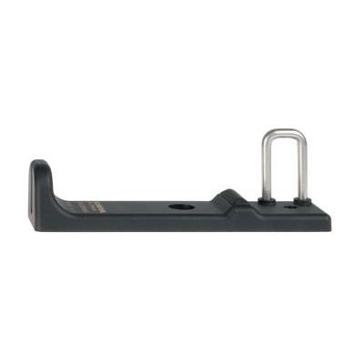
| Recommendation (actuator) |
EX-AZ/AZM300-B1 |
Note
| Note (General) |
Do osłon wpuszczonych w ramę można użyć opcjonalnego zestawu montażowego MP-AZ/AZM300-1. Do osłon wykonanych ze szkła lub Makrolonu można uzyć opcjonalnego zestawu montażowego MS-AZ/AZM300-B1-1 Tak długo, jak aktywator pozostaje włożony do blokady, osłona bezpieczeństwa może być ponownie zaryglowana. W tym przypadku, wyjścia bezpieczeństwa są ponownie załączane, tak, że osłona bezpieczeństwa nie może zostać otwarta. |
Filtro de idiomas
Ficha técnica
Manual de instrucciones y declaración de conformidad
Declaración de conformidad UKCA
SISTEMA-VDMA Biblioteca/Library
Descargar la versión actual de Adobe Reader
Foto de producto (foto individual de catálogo)
Dibujo dimensional Componente básico
103012543 EX-AZ/AZM300-B1
- 3 different directions of actuation
103003172 MP-AZ/AZM300-1
- Adapter plate made of plastic for use on flush doors
- Outer contour optimised for AZM300
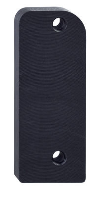
103002891 MS-AZ/AZM300-B1-1
- Aluminium protective plate as a screen
- Threaded heads made of aluminium with M6 thread incl. rubber discs
- For use on glass and plastic doors on machines with high design requirements
Schmersal India Pvt. Ltd., Plot No - G-7/1, Ranjangaon MIDC, Tal. - Shirur, Dist.- Pune 412 220
Los datos e información anteriores se han verificado cuidadosamente. Las imágenes pueden diferir del original. Se pueden encontrar más datos técnicos en los manuales de instrucciones. Sujeto a cambios técnicos y errores.
Generado a 30/3/2025 19:22