BN 65-RZ

BN 65-RZ
Descargas
- With pre-wired cable
- Actuation from side
- with bias magnet
- Non-contact principle
- Long life
- Actuating surface and direction of actuation marked by switch symbol
- Construction form Ø 13 mm
- Thermoplastic enclosure
- Actuating distance up to 60 mm depending on actuating magnet and version
- with central mounting
Ordering data
| Product type description |
BN 65-RZ |
| Article number (order number) |
101055800 |
| EAN (European Article Number) |
4030661009490 |
| eCl@ss number, version 12.0 |
27-27-43-02 |
| eCl@ss number, version 11.0 |
27-27-01-05 |
| eCl@ss number, version 9.0 |
27-27-01-05 |
| ETIM number, version 7.0 |
EC002544 |
| ETIM number, version 6.0 |
EC002544 |
Approvals - Standards
| Certificates |
cULus |
General data
| Working principle |
magnético |
| Housing construction form |
Cilindro, llano |
| Housing material |
Plástico reforzado con fibra de vidrio |
| Gross weight |
75 g |
General data - Features
| Latching |
Sí |
| Suitable for elevators |
Sí |
| bias magnet |
Sí |
| Number of snap-in contacts |
1 |
Mechanical data
| Actuating panels |
desde el lado lateral |
| Actuating element |
Imán |
| Mechanical life, minimum |
1.000.000.000 Operations |
| Actuating speed, maximum |
18 m/s |
| Mounting |
centralizado con brida roscada |
| Tightening torque of nuts, maximum |
3 Nm |
Mechanical data - Switching distances
| Switching distance Sn |
15 mm … 60 mm BP 10N = 15 mm BP 10S = 15 mm 2 x BP 10N = 20 mm 2 x BP 10S = 20 mm BP 15N = 17 mm BP 15S = 17 mm 2 x BP 15/2N = 22 mm 2 x BP 15/2S = 22 mm BP 34N = 10 ... 30 mm BP 34S = 15 ... 30 mm BP 20N = 25 mm BP 20S = 25 mm BP 31N = 25 mm BP 31S = 25 mm BP 11N = 15 mm BP 11S = 15 mm 2 x BP 11N = 25 mm 2 x BP 11S = 25 mm BP 12N = 20 mm BP 12S = 20 mm 2 x BP 12N = 10 ... 30 mm 2 x BP 12S = 10 ... 30 mm BP 21N = 15 ... 45 mm BP 21S = 15 ... 45 mm 2 x BP 21N = 20 ... 60 mm 2 x BP 21S = 20 ... 60 mm BE 20N = 20 mm BE 20S = 20 mm |
| Note (Switching distance Sn) |
Distancia de accionamiento hasta 60 mm, dependiendo del imán de accionamiento y versión. Las especificaciones referente a las distancias de detección/conmutación refieren a la actuación de dispositivos montados individualmente sin influencia ferromagnética. Es posible que la distancia se modifique de manera positiva o negativa debido a influencias ferromagnéticas. Al colocar varios imanes de accionamiento deberá tenerse en cuenta la influencia mutua. |
| Note (switching distance) |
All switching distances in accordance EN IEC 60947-5-2 |
| Repeat accuracy R |
0,3 mm |
Mechanical data - Connection technique
| Length of cable |
1 m |
| Termination |
Cable |
| Wire cross-section |
0,75 mm2 |
| Wire cross-section |
18 AWG |
| Material of the Cable mantle |
H03VV-F |
Mechanical data - Dimensions
| Diameter of sensor |
13 mm |
| width across flats |
22 BK |
| Length of sensor |
103 mm |
Ambient conditions
| Degree of protection |
IP67 |
| Ambient temperature |
-25 ... +75 °C |
| Resistance to vibrations |
10…55 Hz, amplitud 1 mm |
| Restistance to shock |
30 g, de oscilación sinusoidal |
| Resistant to vibration |
30 g, de oscilación sinusoidal |
Electrical data
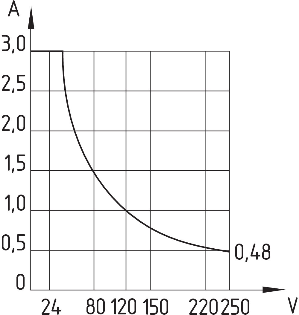
| Switching voltage, maximum |
250 VAC |
| Switching current, maximum |
3 A |
| Switching capacity, maximum |
120 W |
| Switching element |
Contacto bi-estable |
| Bounce duration, minimum |
0,3 ms |
| Bounce duration, maximum |
0,6 ms |
| Switching frequency, maximum |
300 Hz |
| Maximale Schalthäufigkeit |
1.080.000 /h |
Electrical data - Digital Output
| Design of control elements |
Contacto Reed |
Scope of delivery
| Scope of delivery |
Actuator must be ordered separately. |
Accessory
| Recommendation (actuator) |
BP 10 S 2x BP 10 S BP 15 S BP 34 S BP 20 S BP 31 S BP 11 S 2x BP 11 S BP 12 S BP 21 S 2x BP 21 S BE 20 S BP 10 N 2x BP 10 N BP 15 N 2 x BP 15/2 N 2x BP 15/2 S BP 34 N BP 20 N BP 31 N BP 11 N 2x BP 11 N BP 12 N 2x BP 12 N 2x BP 12 S BP 21 N 2x BP 21 N BE 20 N |
| Recommendation (actuator, lift switchgear) |
BP 10 2 x BP 15/2 2 x BP 15 2 x BP 10 BP 15 BP 34 |
Note
| Note (General) |
Otwarcie i zamknięcie zestyków zależy od kierunku aktywacji oraz typu i polaryzacji użytego magnesu aktywującego. Kolory zbliżonych do siebie czujnika i magnesu muszą się pokrywać: Czerwony (S) z czerwonym (S) oraz zielony (N) z zielonym (N). No aplicable al contacto bi-estable. |
Filtro de idiomas
Ficha técnica
Declaración de conformidad CE
Certificado UL
Información
Descargar la versión actual de Adobe Reader
Foto de producto (foto individual de catálogo)
Dibujo dimensional Componente básico
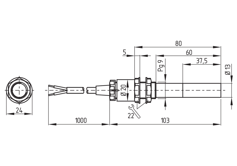
Diagrama de recorridos de contacto
Diagrama de recorridos de contacto

Diagrama
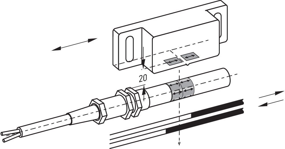
Diagrama

Curva de características
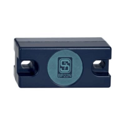
101057432 BP 22 N(S)
- -metal housing
- S-pole marked red
- N-pole marked green
- Suitable for mounting on ferrous material
- Can be used as N or S magnet
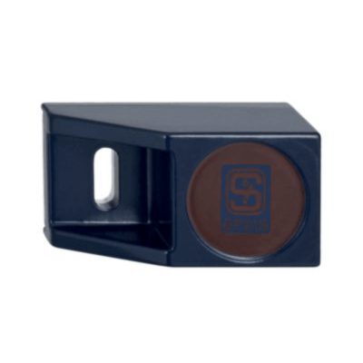
101057534 BP 21 S
- -metal housing
- S-pole marked red
- Suitable for mounting on ferrous material
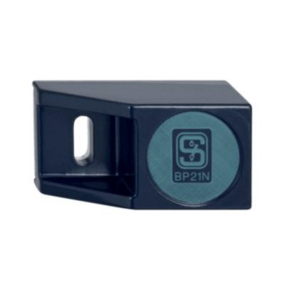
101057536 BP 21 N
- -metal housing
- N-pole marked green
- Suitable for mounting on ferrous material
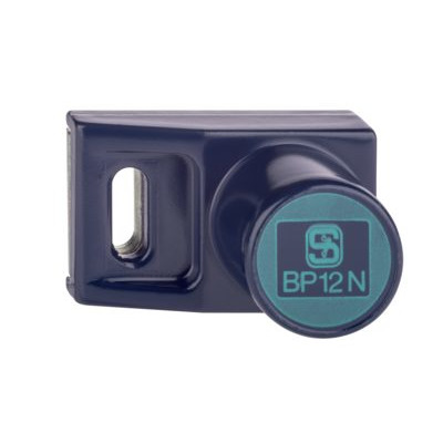
101059917 BP 12 N
- -metal housing
- N-pole marked green
- Suitable for mounting on ferrous material
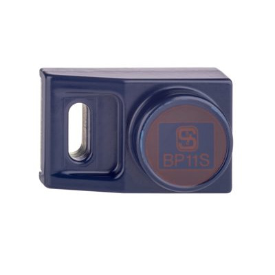
101057533 BP 11 S
- -metal housing
- S-pole marked red
- Suitable for mounting on ferrous material

101059923 BP 11 N
- -metal housing
- N-pole marked green
- Suitable for mounting on ferrous material
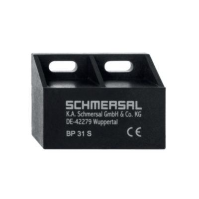
101057521 BP 31 S
- thermoplastic enclosure
- S-pole marked red
- Suitable for mounting on ferrous material with a distance of 20 mm
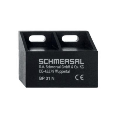
101057520 BP 31 N
- thermoplastic enclosure
- N-pole marked green
- Suitable for mounting on ferrous material with a distance of 20 mm

101057530 BP 31
- thermoplastic enclosure
- S-pole marked red
- N-pole marked green
- Suitable for mounting on ferrous material with a distance of 20 mm
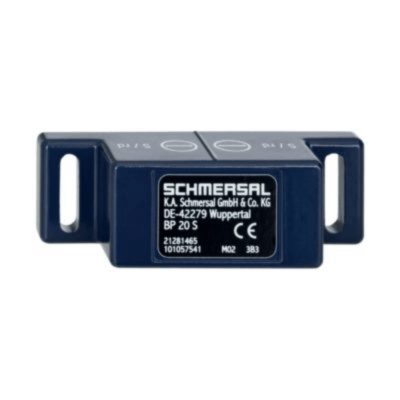
101057541 BP 20 S
- -metal housing
- S-pole marked red
- Suitable for mounting on ferrous material with a distance of 20 mm
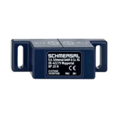
101057538 BP 20 N
- -metal housing
- N-pole marked green
- Suitable for mounting on ferrous material with a distance of 20 mm
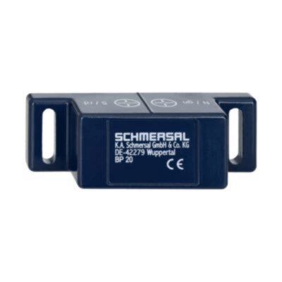
101057549 BP 20
- -metal housing
- S-pole marked red
- N-pole marked green
- Suitable for mounting on ferrous material with a distance of 20 mm
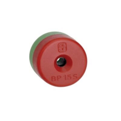
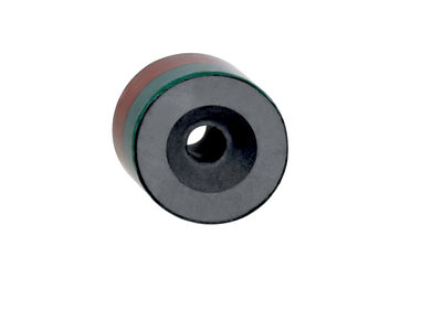
101060163 BP 15
- thermoplastic enclosure
- N-pole marked green
- S-pole marked red
- Suitable for mounting on ferrous material with a distance of 18 mm
101057531 BP 10
- Unenclosed
- Colour coding of poles by lables
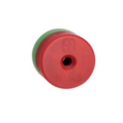
101057553 BP 34
- thermoplastic enclosure
- S-pole marked red
- N-pole marked green
- Suitable for mounting on ferrous material with a distance of 25 mm
Schmersal India Pvt. Ltd., Plot No - G-7/1, Ranjangaon MIDC, Tal. - Shirur, Dist.- Pune 412 220
Los datos e información anteriores se han verificado cuidadosamente. Las imágenes pueden diferir del original. Se pueden encontrar más datos técnicos en los manuales de instrucciones. Sujeto a cambios técnicos y errores.
Generado a 9/4/2025 13:18