SRB202MSL
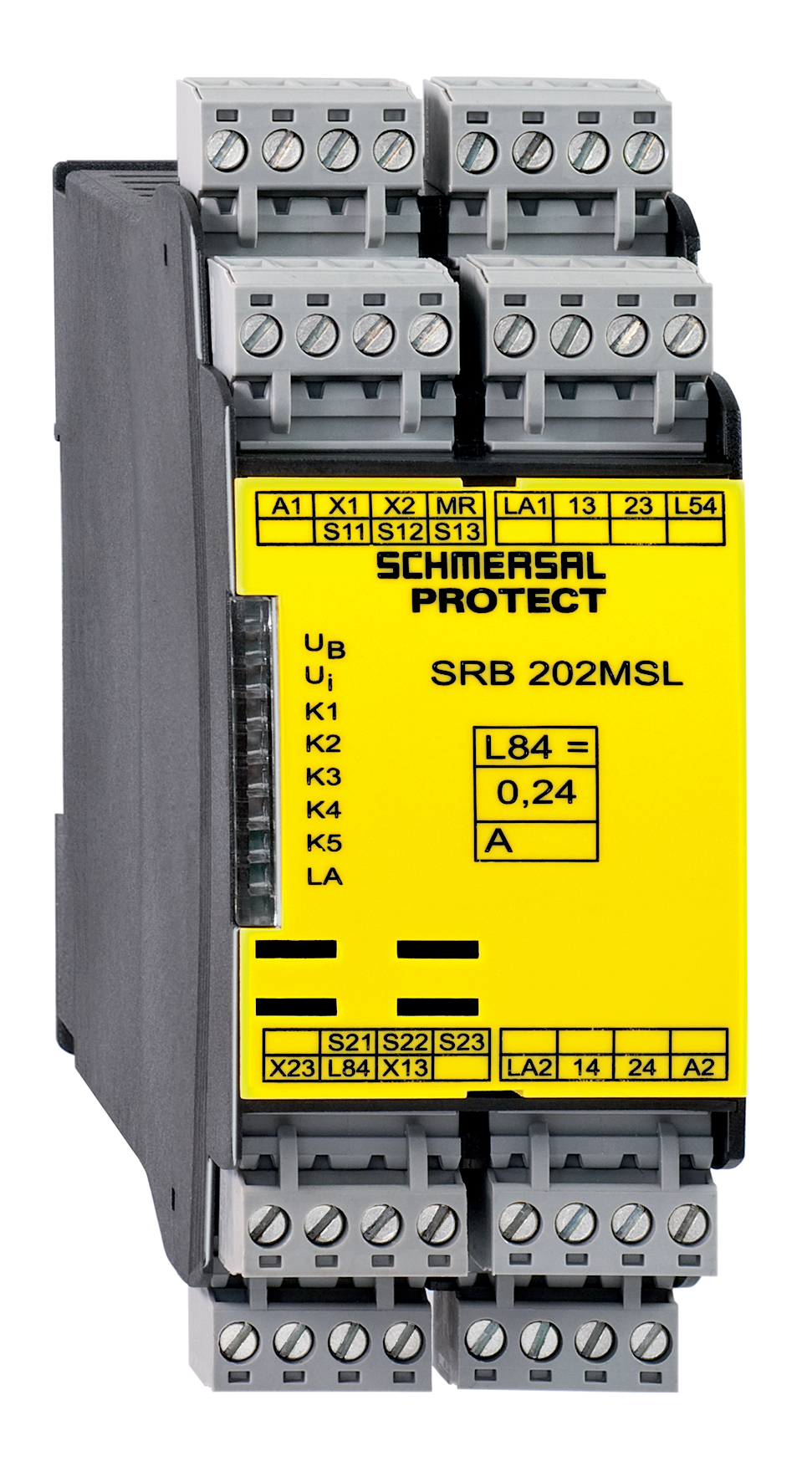
SRB202MSL
Downloads
- Muting signalling device monitoring
- 2 safety contacts, STOP 0
- 2 Signalling outputs
Ordering data
| Note (Delivery capacity) |
Ei saatavana! |
| Product type description |
SRB202MSL |
| Article number (order number) |
101181998 |
| EAN (European Article Number) |
4250116202577 |
| eCl@ss number, version 12.0 |
27-37-18-19 |
| eCl@ss number, version 11.0 |
27-37-18-19 |
| eCl@ss number, version 9.0 |
27-37-18-19 |
| ETIM number, version 7.0 |
EC001449 |
| ETIM number, version 6.0 |
EC001449 |
General data
| Standards |
EN IEC 62061 EN ISO 13849-1 EN IEC 60947-5-1 EN IEC 60947-5-3 EN IEC 60947-5-5 EN IEC 61508 EN IEC 60204-1 EN IEC 60947-1 |
| Climatic stress |
EN 60068-2-78 |
| Housing material |
Muovi, lasikuituvahvistettu kestomuovi, tuuletettu |
| Gross weight |
400 g |
General data - Features
| Electronic Fuse |
Kyllä |
| Wire breakage detection |
Kyllä |
| Cross-circuit detection |
Kyllä |
| Removable Terminals |
Kyllä |
| Feedback circuit |
Kyllä |
| Automatic reset function |
Kyllä |
| Reset after disconnection of supply voltage |
Kyllä |
| Earth connection detection |
Kyllä |
| Integral system diagnostics, status |
Kyllä |
| Number of auxiliary contacts |
2 |
| Number of LEDs |
8 |
| Number of normally closed (NC) |
2 |
| Number of safety contacts |
2 |
| Number of signalling outputs |
2 |
| Safety classification |
| Vorschriften |
EN IEC 60947-5-1 EN IEC 61508 |
| Stop-Category |
0 |
| Safety classification - Relay outputs |
| Performance Level, stop 0, up to |
e |
| Category, Stop 0 |
4 |
| Diagnostic Coverage (DC) Level, Stop 0 |
≥ 99 % |
| PFH value, Stop 0 |
2,00 x 10⁻⁸ /h |
| Safety Integrity Level (SIL), Stop 0, suitable for applications in |
3 |
| Mission time |
20 Year(s) |
| Common Cause Failure (CCF), minimum |
65 |
Mechanical data
| Mechanical life, minimum |
10 000 000 Operations |
| Mounting |
Pikakiinnitys DIN-kiskoon standardin DIN EN 60715 mukaan |
Mechanical data - Connection technique
| Terminal designations |
IEC/EN 60947-1 |
| Termination |
Jäykkä tai taipuisa Ruuviliitäntä M20 x 1.5 |
| Cable section, minimum |
0,25 mm² |
| Cable section, maximum |
2,5 mm² |
| Tightening torque of Clips |
0,6 Nm |
Mechanical data - Dimensions
| Width |
45 mm |
| Height |
100 mm |
| Depth |
121 mm |
Ambient conditions
| Degree of protection of the enclosure |
IP40 |
| Degree of protection of the mounting space |
IP54 |
| Degree of protection of clips or terminals |
IP20 |
| Ambient temperature |
-25 ... +45 °C |
| Storage and transport temperature |
-40 ... +85 °C |
| Resistance to vibrations |
10...55 Hz, Amplitudi 0,35 mm, ± 15 % |
| Restistance to shock |
30 g / 11 ms |
Ambient conditions - Insulation values
| Rated impulse withstand voltage Uimp |
4 kV |
| Overvoltage category |
III |
| Degree of pollution |
2 |
Electrical data
| Frequency range |
50 Hz 60 Hz |
| Operating voltage |
24 VDC -10 % / +20 % |
| Ripple voltage |
10 % |
| Rated operating voltage |
24 VDC |
| Rated AC voltage for controls at DC minimum |
20,4 VDC |
| Rated control voltage at DC, maximum |
28,8 VDC |
| Utilisation category DC-13 |
24 VDC |
| Utilisation category DC-13 |
2 A |
| Electrical power consumption |
5,6 W |
| Contact resistance, maximum |
0,1 Ω |
| Note (Contact resistance) |
uutena |
| Drop-out delay in case of power failure, typically |
60 ms |
| Drop-out delay in case of emergency, typically |
17 ms |
| Drop-out delay in case of "emergency stop", maximum |
20 ms |
| Pull-in delay at automatic start, maximum, typically |
200 ms |
| Material of the contacts, electrical |
AgSn0. Ag-Ni, itsepuhdistuva, pakkotoiminto |
Electrical data - Digital inputs
| Conduction resistance, maximum |
40 Ω |
Electrical data - Electromagnetic compatibility (EMC)
| EMC rating |
EMC-Directive |
Status indication
| Indicated operating states |
Releiden K2 tila Releiden K1 tila Sisäinen käyttöjännite Ui Releiden K3 tila Releiden K5 tila Passivointimerkkivalon LA tila |
Other data
| Note (applications) |
passivointi |
Note
| Note (General) |
Inductive loads (e.g. contactors, relays, etc.) are to be suppressed by means of a suitable circuit. |
Wiring example
| Note (Wiring diagram) |
Relelähdöt: 2-kanavainen ohjaus kontaktorien tai releiden pakkotoimisten koskettimien kautta mahdollistaa koskettimien kapasiteetin tai lukumäärän lisäämiseen . Ohjain tunnistaa valvontapiirissä olevan oikosulun, johdinkatkon ja maasulun. Esimerkissä näkyy 2-kanavainen kytkentä, 2 passivointianturia ja ulkoinen master-kuittauspainike. Kytkentäkaavion kytkennät on kuvattu jännitteettömässä tilassa passivointianturien ollessa vapaina. (H2) = takaisinkytkentäpiiri F1 = elektroninen sulake |
Kielisuodatin
Tuotelehti
Asennus- ja kytkentäohjeet
Käyttöohjeet ja vaatimuksenmukaisuusvakuutus
Kytkentäesimerkki (johdotus)
Lattaa Adobe Readerin viimeisin versio
Tuotekuva( luettelokuva)
Kytkentäesimerkki

Merkki (tekninen standardi)

Schmersal India Pvt. Ltd., Plot No - G-7/1, Ranjangaon MIDC, Tal. - Shirur, Dist.- Pune 412 220
Tiedot ja arvot on tarkastettu huolellisesti. Kuvat voivat poiketa alkuperäisestä. Tarkemmat tekniset tiedot löytyvät manuaalista. Pidätämme oikeuden teknisiin muutoksiin ja virheisiin.
Luotu: 25.4.2025 1.09
Viimeksi katsottu