SRB400CS 24VDC
SRB400CS 24VDC
Téléchargements
- Level 1: Reset without edge detection, Optional Automatic reset function, Level 2: / Opener (NC) Opener (NC)
- Two-functions safety monitoring module (double evaluation)
- 2 x 2 enabling paths with different shut-down behaviour, e.g. emergency exit opens both enabling paths (level 1); guard door monitoring only opens the second enabling path (level 2)
- Suitable for signal processing of potential-free contacts, e.g. Emergency Stop command devices (level 1), position switches with safety function, solenoid interlocks and safety sensors (level 2)
Ordering data
| Replacement article number |
101177160 |
| Product type description |
SRB400CS 24VDC |
| Article number (order number) |
101176209 |
| EAN (European Article Number) |
4250116201938 |
| eCl@ss number, version 12.0 |
27-37-18-19 |
| eCl@ss number, version 11.0 |
27-37-18-19 |
| eCl@ss number, version 9.0 |
27-37-18-19 |
| ETIM number, version 7.0 |
EC001449 |
| ETIM number, version 6.0 |
EC001449 |
| Notice |
Produit de fin de série |
Approvals - Standards
| Certificates |
cULus |
General data
| Standards |
EN IEC 62061 EN ISO 13849-1 EN IEC 60947-5-1 EN IEC 60947-5-3 EN IEC 60947-5-5 EN IEC 61508 EN IEC 60204-1 EN IEC 60947-1 |
| Climatic stress |
EN 60068-2-78 |
| Housing material |
Plastique, thermoplastique renforcée de fibres de verre, ventilée |
| Gross weight |
235 g |
General data - Features
| Electronic Fuse |
Oui |
| Wire breakage detection |
Oui |
| Removable Terminals |
Oui |
| Start input |
Oui |
| Feedback circuit |
Oui |
| Automatic reset function |
Oui |
| Earth connection detection |
Oui |
| Integral system diagnostics, status |
Oui |
| Number of inputs for NC |
2 |
| Number of inputs for NO |
2 |
| Number of LEDs |
6 |
| Number of safety contacts |
4 |
| Safety classification |
| Vorschriften |
EN IEC 60947-5-1 EN IEC 61508 |
| Stop-Category |
0 |
| Safety classification - Relay outputs |
| Performance Level, stop 0, up to |
e |
| Category, Stop 0 |
4 |
| Diagnostic Coverage (DC) Level, Stop 0 |
≥ 99 % |
| PFH value, Stop 0 |
2,00 x 10⁻⁸ /h |
| Safety Integrity Level (SIL), Stop 0, suitable for applications in |
3 |
| Mission time |
20 Year(s) |
| Common Cause Failure (CCF), minimum |
65 |
Mechanical data
| Mechanical life, minimum |
10 000 000 Operations |
| Mounting |
Fixation rapide sur rails DIN standards selon DIN EN 60715 |
Mechanical data - Connection technique
| Terminal designations |
IEC/EN 60947-1 |
| Termination |
rigide ou flexible Raccord fileté M20 x 1.5 |
| Cable section, minimum |
0,25 mm² |
| Cable section, maximum |
2,5 mm² |
| Tightening torque of Clips |
0,6 Nm |
Mechanical data - Dimensions
| Width |
22,5 mm |
| Height |
100 mm |
| Depth |
121 mm |
Ambient conditions
| Degree of protection of the enclosure |
IP40 |
| Degree of protection of the mounting space |
IP54 |
| Degree of protection of clips or terminals |
IP20 |
| Ambient temperature |
-25 ... +45 °C |
| Storage and transport temperature |
-40 ... +85 °C |
| Resistance to vibrations |
10 ... 55 Hz, amplitude 0,35 mm |
| Restistance to shock |
10 g / 11 ms |
Ambient conditions - Insulation values
| Rated impulse withstand voltage Uimp |
4 kV |
| Overvoltage category |
III |
| Degree of pollution |
2 |
Electrical data
| Operating voltage |
24 VDC -10 % / +20 % |
| Ripple voltage |
10 % |
| Rated operating voltage |
24 VDC |
| Rated AC voltage for controls at DC minimum |
20,4 VDC |
| Rated control voltage at DC, maximum |
28,8 VDC |
| Electrical power consumption |
4,4 W |
| Contact resistance, maximum |
0,1 Ω |
| Note (Contact resistance) |
à l'état neuf |
| Drop-out delay in case of power failure, typically |
80 ms |
| Drop-out delay in case of emergency, typically |
20 ms |
| Pull-in delay at automatic start, maximum, typically |
100 ms |
| ON delay at automatic start |
Réglable avec démarrage automatique |
| Pull-in delay at RESET, typically |
20 ms |
| Material of the contacts, electrical |
Ag-Ni, autonettoyant, à guidage forcé |
Electrical data - Safe relay outputs
| Voltage, Utilisation category AC-15 |
250 VAC |
| Current, Utilisation category AC-15 |
6 A |
| Voltage, Utilisation category DC-13 |
24 VDC |
| Current, Utilisation category DC-13 |
6 A |
| Switching capacity, minimum |
10 VDC |
| Switching capacity, minimum |
10 mA |
| Switching capacity, maximum |
250 VAC |
| Switching capacity, maximum |
8 A |
Electrical data - Digital inputs
| Conduction resistance, maximum |
40 Ω |
Electrical data - Relay outputs (auxiliary contacts)
| Switching capacity, maximum |
24 VDC |
| Switching capacity, maximum |
2 A |
Electrical data - Electromagnetic compatibility (EMC)
| EMC rating |
Directive CEM |
Status indication
| Indicated operating states |
Position relais K2 Position relais K1 Tension de service interne Ui Position relais K3 |
Other data
| Note (applications) |
Capteur de sécurité Dispositif de protection Bouton d'arrêt d'urgence Interrupteurs de sécurité à commande par câble |
Note
| Note (General) |
Des charges inductives (p.ex. relais externe, etc.) doivent être antiparasitées par un dispositif approprié. |
| Note (Cross-circuit detection) |
Niveau 1 |
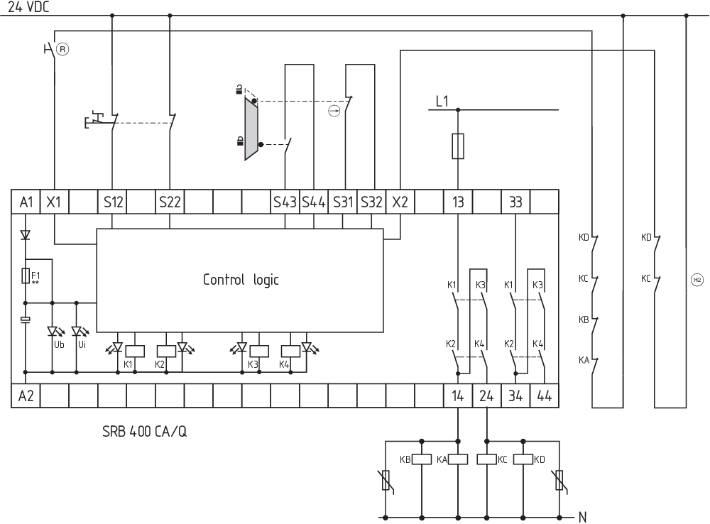
Wiring example
| Note (Wiring diagram) |
L'exemple de câblage est représenté pour les protecteurs fermés et hors tension. Partie puissance: une commande à 2 canaux convient pour le renforcement ou la multiplication des contacts par contacteurs ou relais avec contacts à guidage forcé. La commande détecte les courts-circuits transversaux, les ruptures de câbles et les fuites à la terre dans le circuit de surveillance. Niveau d'entrée: l'exemple reprend une commande à 2 canaux d'un dispositif d'arrêt d'urgence (niveau 1) avec bouton de réarmement externe (R) et une surveillance de protecteur (niveau 2) avec boucle de retour (H2). Démarrage automatique (niveau 1): le démarrage automatique est configuré en raccordant la boucle de retour aux bornes X1/+24VDC. Démarrage automatique (niveau 2): le démarrage automatique est configuré en raccordant la boucle de retour aux bornes X2/+24VDC. Si la boucle de retour n'est pas utilisée, établir un pont |
Filtre de langue
Fiches techniques
Mode d'emploi et déclaration de conformité
Certificat UL
Exemple de câblage (câblage électrique)
Télécharger la dernière version d'Adobe Reader
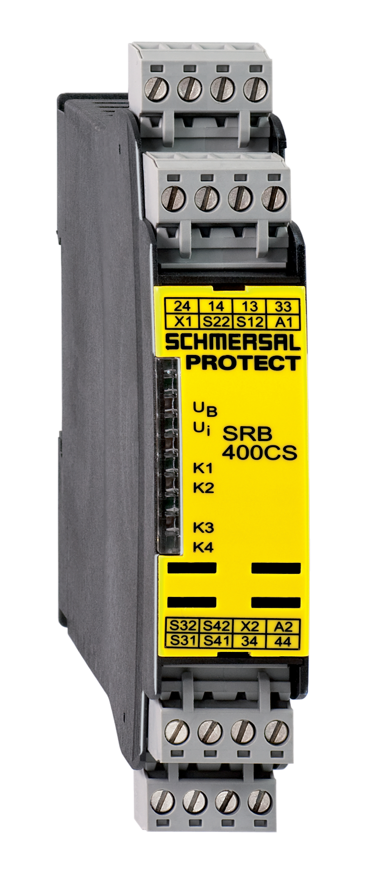
Photo du produit (photo individuelle de catalogue)
Exemple de câblage
Exemple de câblage
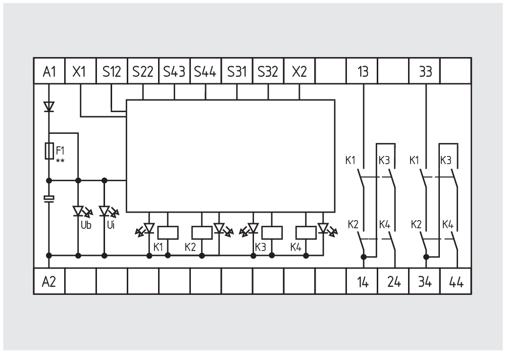
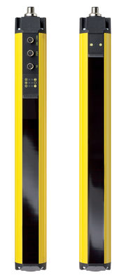
Symbole (norme technique)

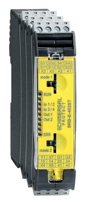
103007221 SRB-E-402ST
- Two-functions safety monitoring module (double evaluation), 2 x STOP 0
- 2 x 1 oder 2-channel control
- 2 x Start button / Auto-start
- 1 x Monitoring two-hand control panels to ISO 13851
- 2 safety contacts
- 2 Safety outputs
Schmersal India Pvt. Ltd., Plot No - G-7/1, Ranjangaon MIDC, Tal. - Shirur, Dist.- Pune 412 220
Les données et les valeurs ont été soigneusement vérifiées. Les illustrations peuvent être différentes de l'original. Vous trouverez d'avantage de caractéristiques techniques dans les manuels d’instructions. Sous réserve de modifications techniques et errata.
Généré le: 24/04/2025 21:41
Récemment consultés