AES 1165.3-2214-1 24 VAC
AES 1165.3-2214-1 24 VAC
- Monitoring of BNS range magnetic safety sensors
- 1 safety contact, STOP 0
Ordering data
| Note (Delivery capacity) |
Niet meer verkrijgbaar! |
| Product type description |
AES 1165.3-2214-1 24 VAC |
| Article number (order number) |
101131305 |
| EAN (European Article Number) |
4030661049656 |
| eCl@ss number, version 12.0 |
27-37-18-19 |
| eCl@ss number, version 11.0 |
27-37-18-19 |
| eCl@ss number, version 9.0 |
27-37-18-19 |
| ETIM number, version 7.0 |
EC001449 |
| ETIM number, version 6.0 |
EC001449 |
| Notice |
Discontinued product |
Approvals - Standards
| Certificates |
cULus |
General data
| Standards |
BG-GS-ET-14 BG-GS-ET-20 EN IEC 62061 EN ISO 13849-1 EN IEC 60947-5-1 EN IEC 60947-5-3 EN IEC 60947-5-5 EN IEC 60204-1 EN IEC 60947-1 |
| Climatic stress |
BG-GS-ET-14 IEC 60947-5-3 |
| Housing material |
Kunststof, glasvezelversterkte thermoplast, geventileerd |
| Gross weight |
164 g |
General data - Features
| Wire breakage detection |
Ja |
| Cross-circuit detection |
Ja |
| Automatic reset function |
Ja |
| Reset after disconnection of supply voltage |
Ja |
| Earth connection detection |
Ja |
| Integral system diagnostics, status |
Ja |
| Number of auxiliary contacts |
2 |
| Number of inputs for NC |
2 |
| Number of inputs for NO |
1 |
| Number of LEDs |
1 |
| Number of safety contacts |
1 |
| Number of signalling outputs |
2 |
| Safety classification |
| Vorschriften |
EN ISO 13849-1 EN IEC 61508 |
| Stop-Category |
0 |
| Safety classification - Relay outputs |
| Performance Level, up to |
d |
| Category |
3 |
| PFH value |
1,00 x 10⁻⁷ /h |
| Notice |
Geldt voor toepassingen tot max. 50.000 schakelcycli/jaar en met max. 80 % contactlast. |
| Safety Integrity Level (SIL), suitable for applications in |
2 |
| Mission time |
20 Year(s) |
Mechanical data
| Mechanical life, minimum |
20.000.000 Operations |
| Mounting |
Snelbevestiging voor DIN-rail volgens DIN EN 60715 |
Mechanical data - Connection technique
| Terminal designations |
IEC/EN 60947-1 |
| Termination |
stijf of flexibel Schraubanschluss M20 x 1.5 |
| Cable section, minimum |
0,25 mm² |
| Cable section, maximum |
2,5 mm² |
| Tightening torque of Clips |
0,6 Nm |
Mechanical data - Dimensions
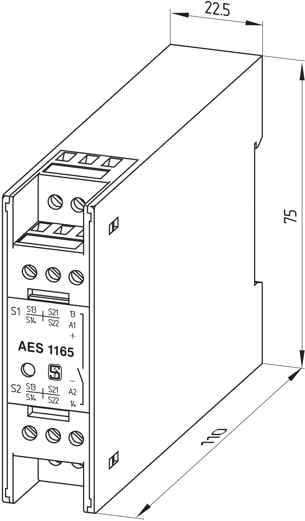
| Width |
22,5 mm |
| Height |
100 mm |
| Depth |
121 mm |
Ambient conditions
| Degree of protection of the enclosure |
IP40 |
| Degree of protection of the mounting space |
IP54 |
| Degree of protection of clips or terminals |
IP20 |
| Ambient temperature |
+0 ... +55 °C |
| Storage and transport temperature |
-25 ... +70 °C |
| Resistance to vibrations |
10...55 Hz, Amplitude 0,35 mm, ± 15 % |
| Restistance to shock |
30 g / 11 ms |
Ambient conditions - Insulation values
| Rated impulse withstand voltage Uimp |
4 kV |
| Overvoltage category |
III |
| Degree of pollution |
2 |
Electrical data
| Frequency range |
50 Hz 60 Hz |
| Operating voltage |
24 VAC -15 % / +10 % |
| Ripple voltage |
10 % |
| Thermal test current |
6 A |
| Rated operating voltage |
24 VAC |
| Rated AC voltage for controls, 50 Hz, minimum |
20,4 VAC |
| Rated control voltage at AC 50 Hz, maximum |
26,4 VAC |
| Rated AC voltage for controls, 60 Hz, minimum |
20,4 VAC |
| Rated control voltage at AC 60 Hz, maximum |
26,4 VAC |
| Rated AC voltage for controls at DC minimum |
20,4 VDC |
| Rated control voltage at DC, maximum |
28,8 VDC |
| Electrical power consumption |
5 W |
| Contact resistance, maximum |
0,1 Ω |
| Note (Contact resistance) |
In nieuwe toestand |
| Drop-out delay in case of power failure, typically |
80 ms |
| Drop-out delay in case of emergency, typically |
20 ms |
| Pull-in delay at automatic start, maximum, typically |
100 ms |
| Pull-in delay at RESET, typically |
20 ms |
| Material of the contacts, electrical |
Ag-Ni 10 en 0 2 µm verguld |
Electrical data - Safe relay outputs
| Voltage, Utilisation category AC-15 |
230 VAC |
| Current, Utilisation category AC-15 |
6 A |
| Voltage, Utilisation category DC-13 |
24 VDC |
| Current, Utilisation category DC-13 |
6 A |
| Switching capacity, minimum |
10 VDC |
| Switching capacity, minimum |
10 mA |
| Switching capacity, maximum |
250 VAC |
| Switching capacity, maximum |
8 A |
Electrical data - Digital inputs
| Input signal, HIGH Signal "1" |
10 … 30 VDC |
| Input signal, LOW Signal "0" |
0 … 2 VDC |
| Conduction resistance, maximum |
40 Ω |
Electrical data - Digital Output
| Voltage, Utilisation category DC-12 |
24 VDC |
| Current, Utilisation category DC-12 |
0,1 A |
Electrical data - Relay outputs (auxiliary contacts)
| Switching capacity, maximum |
24 VDC |
| Switching capacity, maximum |
2 A |
Electrical data - Electromagnetic compatibility (EMC)
| EMC rating |
EMC-Richtlijn |
Integral system diagnosis (ISD)
| Note (ISD -Faults) |
De volgende fouten worden door de veiligheidsmodules herkend en door ISD weergegeven. |
| Faults |
Niet-aantrekken of niet-afvallen van de veiligheidsrelais Niet-openen of niet-sluiten van de deurcontacten Dwars- of kortsluitingen aan de aansluitkabels Onderbreking van de aansluitkabels Fout aan de ingangsschakelingen of aan de relaisaansturingen van de veiligheidsmodule |
Other data
| Note (applications) |
Veiligheidssensor Beschermvoorziening |
Note
| Note (General) |
Inductieve verbruikers (externe relais, enz.) zijn via een aangepaste bedrading te ontstoren. |
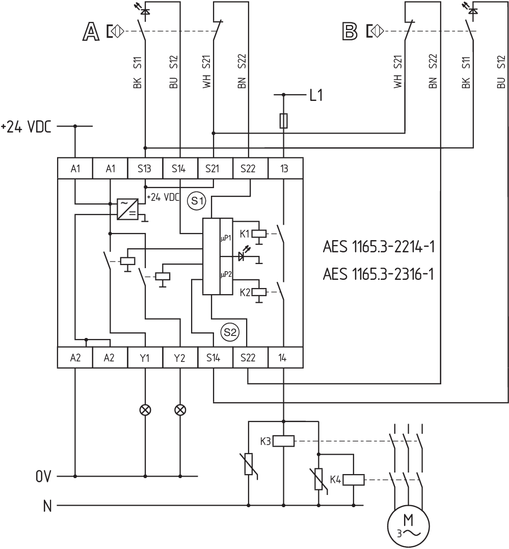
Wiring example
| Note (Wiring diagram) |
Het schakelvoorbeeld is afgebeeld bij gesloten beschermvoorzieningen en in spanningsloze toestand. Bewaking van 2 beschermvoorziening(en) met telkens een magnetische veiligheidssensor van de serie BNS Als één of twee externe relais gebruikt worden voor het schakelen van de last, kan het systeem alleen in categorie 3 volgens EN ISO 13849-1 ingedeeld worden, als het uitsluiten van de fout „Falen van het externe relais“ toegelicht en gedocumenteerd kan worden, bijvoorbeeld bij gebruik van een betrouwbaar oversized extern relais. Een tweede extern relais leidt tot een verhoogde veiligheid door redundante uitschakeling van de lading Een tweede extern relais leidt tot een verhoogde veiligheid door redundante uitschakeling van de lading. De ISD-tabellen (geïntegreerde systeemdiagnose) voor analyse van de foutmeldingen en hun oorzaken worden in bijlage vermeld. Verlenging van de tijdvertraging: Door het omsteken van een brug onder de behuizingdeksel kan de tijdvertraging van 0,1 s op 1 s ingesteld worden. Ter beveiliging van 2 beschermvoorzieningen tot PL d en categorie 3 |
Taalfilter
Datasheet
Bedieningshandleiding en conformiteitsverklaring
UL-certificaat
Informatie
Schakelvoorbeeld (elektrische kabels)
SISTEMA-VDMA-bibliotheek/library
Download de nieuwste versie van Adobe Reader
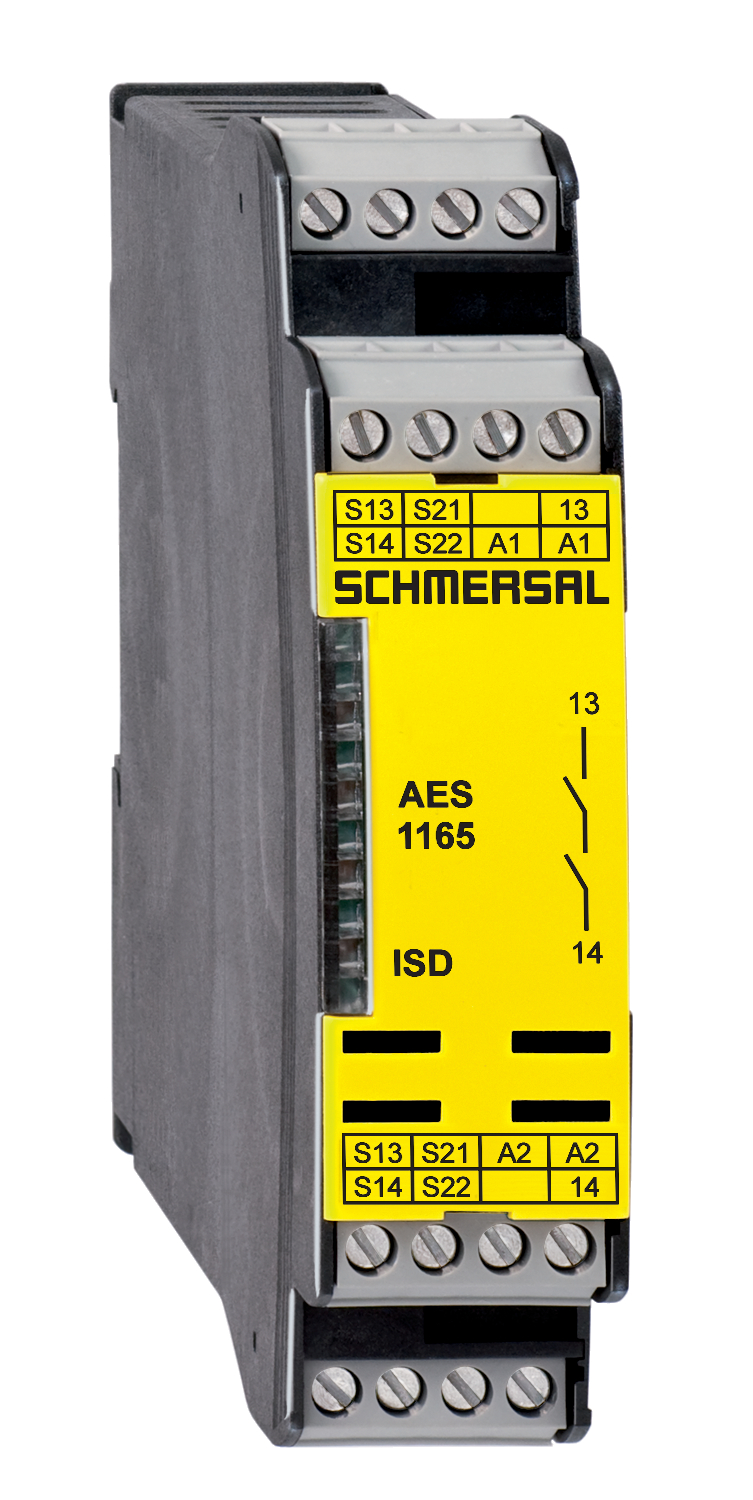
Foto van het product (individuele catalogusfoto)
Maatschets basistoestel
Schakelvoorbeeld
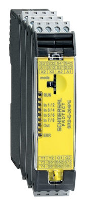
103008070 SRB-E-204PE
- Plug-in screw terminals with coding
- Input expander module
- 1 oder 2-channel control
- Monitoring of 4 sensors
- 2 Safety outputs
- 4 Signalling outputs

103009973 SRB-E-204ST
- Plug-in screw terminals with coding
- STOP 0 Function
- Monitoring of 4 sensors
- Start button / Auto-start
- 2 Safety outputs
- 4 Signalling outputs
Schmersal India Pvt. Ltd., Plot No - G-7/1, Ranjangaon MIDC, Tal. - Shirur, Dist.- Pune 412 220
De genoemde gegevens en informatie zijn zorgvuldig gecontroleerd. Afbeeldingen kunnen afwijken van het origineel. Verdere technische gegevens zijn te vinden in de handleiding. Technische wijzigingen en fouten voorbehouden.
Gegenereerd op 25-03-2025 19:31